منطقة ونغ يانغ الصناعية يويتشينغ ونتشو 325000
ساعات العمل
من الاثنين إلى الجمعة: 7 صباحاً - 7 مساءً
عطلة نهاية الأسبوع 10 صباحاً - 5 مساءً
منطقة ونغ يانغ الصناعية يويتشينغ ونتشو 325000
ساعات العمل
من الاثنين إلى الجمعة: 7 صباحاً - 7 مساءً
عطلة نهاية الأسبوع 10 صباحاً - 5 مساءً

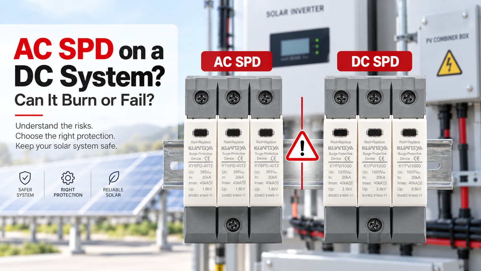
إن استخدام جهاز حماية من زيادة التيار (SPD) مخصص للتيار المتردد في نظام تيار مستمر قد يكون خطيراً إذا لم يكن الجهاز مصنفاً خصيصاً لتطبيق التيار المستمر.
قد يبدو جهاز الحماية من زيادة التيار (SPD) المخصص للتيار المتردد وذلك المخصص للتيار المستمر متشابهين جداً من الخارج، لكنهما ليسا قابلين للتبديل تلقائياً. ومن أكثر الأخطاء شيوعاً الاكتفاء بمقارنة الجهد المطبوع على الملصق. على سبيل المثال، قد يرى شخص ما “1000 فولت” على جهاز حماية ويفترض أنه يمكن تركيبه في نظام طاقة شمسية يعمل بتيار مستمر بجهد 1000 فولت.
هذا الافتراض قد يكون خطيراً.
يجب ألا يتم تركيب جهاز الحماية من زيادة التيار (SPD) في نظام تيار مستمر إلا إذا صنفته الشركة المصنعة خصيصاً لهذا التطبيق، وكانت خصائصه الكهربائية تتوافق مع النظام.
إن استخدام جهاز حماية من اندفاع التيار (SPD) مخصص للتيار المتردد (AC) فقط في دائرة تيار مستمر (DC) قد يؤدي إلى ارتفاع درجة الحرارة، أو فشل آلية الفصل الداخلية، أو حدوث قوس كهربائي مستمر، أو احتراق، أو نشوب حريق. وفي حالات الفشل الشديد، قد يتمزق غلاف جهاز الحماية.
إذن، هل يمكن أن ينفجر جهاز حماية التيار المتردد (AC SPD) عند توصيله بتيار مستمر (DC)؟
ليس بالضرورة. ولكن استخدام جهاز حماية غير مناسب قد يخلق مخاطر فشل جسيمة، وقد يؤدي الفشل الحراري أو الكهربائي الشديد إلى تمزق الغلاف.
لا ينبغي استخدام جهاز حماية التيار المتردد (AC SPD) في نظام تيار مستمر (DC) لمجرد أن قيمة الجهد تبدو متشابهة.
تم تصميم واختبار الجهاز المخصص للتيار المتردد (AC) فقط ليعمل وفق ظروف أنظمة التيار المتردد. أما جهاز حماية التيار المستمر (DC SPD) الخاص بالأنظمة الكهروضوئية فقد صُمم ليتحمل جهد التيار المستمر المستمر، وظروف الأعطال، وتكوين النظام، ومتطلبات الفصل الموجودة في جانب التيار المستمر من التركيبات الكهروضوئية.
بالنسبة للأنظمة الكهروضوئية، تحقق دائماً من التصنيف الكامل لجهاز الحماية (SPD)، وخاصة: Ucpv، وIn، وImax، وIimp حيثما ينطبق ذلك، وUp، وIscpv، ونوع جهاز الحماية (SPD)، وتكوين التوصيل، والمعيار المطبق..
في العادة، لا ينبغي استخدام جهاز حماية من اندفاع التيار (SPD) المخصص للتيار المتردد فقط في أنظمة التيار المستمر.
الكلمة المهمة هي “المُصنَّف”.”
إذا حددت الشركة المصنعة بوضوح أن جهاز حماية من اندفاع التيار (SPD) معين مناسب لتطبيقات التيار المتردد والتيار المستمر، فيمكن استخدامه ضمن التصنيفات وظروف التركيب المذكورة.
ومع ذلك، لا ينبغي تركيب جهاز حماية من اندفاع التيار (SPD) يحمل علامة للاستخدام مع التيار المتردد فقط في دائرة تيار مستمر بشكل تلقائي.
على سبيل المثال:
| علامة جهاز حماية من اندفاع التيار (SPD) | نظام | هل هو مناسب؟ |
|---|---|---|
| جهد التشغيل المستمر الأقصى (Uc) 275 فولت تيار متردد | نظام طاقة شمسية كهروضوئي بجهد 600 فولت تيار مستمر | لا يوجد |
| جهد التشغيل المستمر الأقصى 440 فولت تيار متردد | نظام طاقة شمسية كهروضوئي بجهد 1000 فولت تيار مستمر | لا يوجد |
| جهد التشغيل المستمر الأقصى لنظام الطاقة الشمسية 1000 فولت تيار مستمر | نظام طاقة شمسية كهروضوئي مناسب ضمن التصنيف | من المحتمل نعم |
| جهاز حماية من اندفاع التيار (SPD) ثنائي التصنيف للتيار المتردد/المستمر | مطابقة نظام التيار المتردد أو التيار المستمر | تحقق من مواصفات الشركة المصنعة |
لهذا السبب لا يكفي قراءة رقم الجهد فقط.
تصنيف 1000 فولت تيار متردد و1000 فولت تيار مستمر ليس لنفس التطبيق.
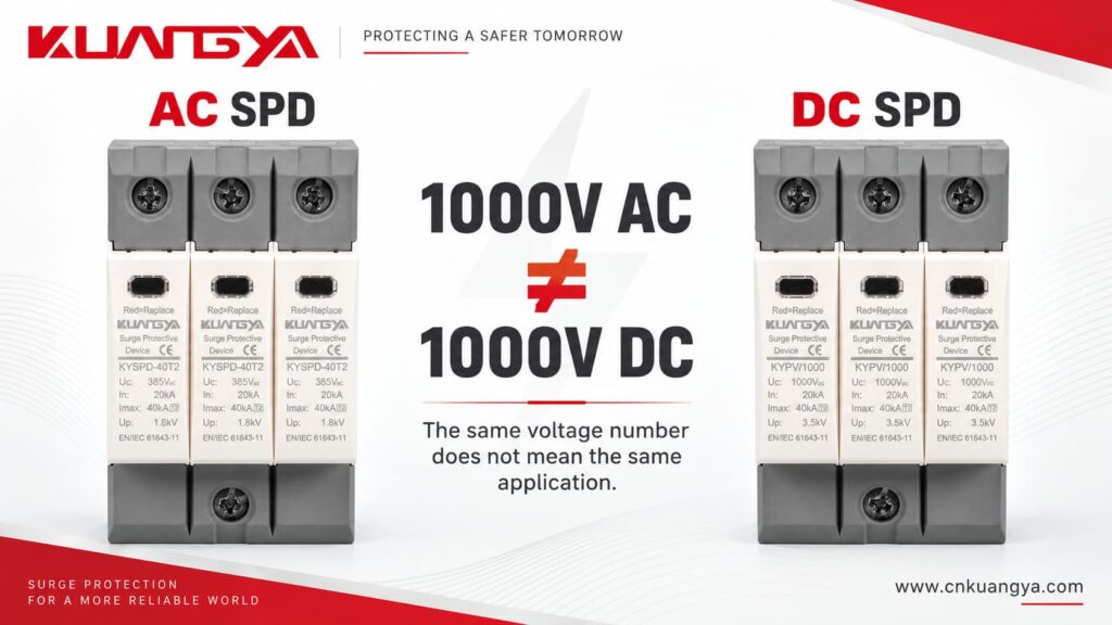
الحروف التي تلي الرقم مهمة.
تؤدي أجهزة الحماية من زيادة التيار (SPD) لكل من التيار المتردد والتيار المستمر نفس الوظيفة الأساسية: فهي تساعد في الحد من الجهد الزائد العابر وتحويل تيار الاندفاع بعيداً عن المعدات الحساسة.
لكن البيئات الكهربائية التي تعمل فيها مختلفة.
يصبح هذا الاختلاف مهماً بشكل خاص أثناء الظروف غير الطبيعية وعند نهاية العمر الافتراضي لجهاز الحماية من زيادة التيار (SPD).
في نظام التيار المتردد الجيبي الطبيعي، تمر الجهد والتيار اللحظي دورياً عبر الصفر.
عند تردد 50 هرتز أو 60 هرتز، يحدث هذا بشكل متكرر كل ثانية.
يمكن لنقاط عبور الصفر الطبيعية أن تساعد في إخماد القوس الكهربائي عند فتح جهاز التبديل أو الفصل.
هذا أحد الأسباب التي تجعل المعدات المصممة لتبديل التيار المتردد وقطع الأعطال لا يمكن افتراض عملها بأمان تلقائياً في ظروف التيار المستمر (DC).
يحافظ مصدر التيار المستمر على نفس القطبية ولا يمر طبيعياً عبر الصفر بنفس الطريقة التي يمر بها التيار المتردد.
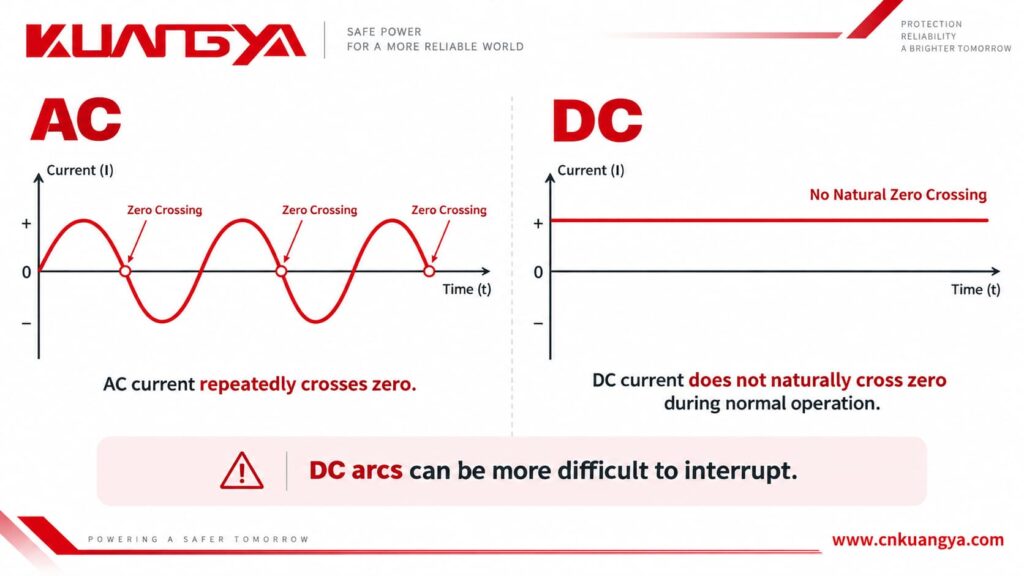
إذا تشكل قوس كهربائي في التيار المستمر، فقد يكون من الصعب إطفاؤه مقارنة بالتيار المتردد.
هذا الأمر مهم في الأنظمة الكهروضوئية لأن المصفوفة الشمسية يمكنها الاستمرار في توفير طاقة التيار المستمر طالما أن ضوء الشمس متاح.
إذا تعرض جهاز الحماية من زيادة التيار (SPD) للحمل الزائد واضطر نظام الفصل الداخلي الخاص به إلى عزل مكون الحماية التالف، فيجب أن يكون الجهاز مصمماً للتعامل مع ظروف التيار المستمر بأمان.
هذا أحد الأسباب التي تجعل أجهزة الحماية من زيادة التيار (SPDs) المخصصة للأنظمة الكهروضوئية تستخدم تصميمات وترتيبات فصل مخصصة لتطبيقات التيار المستمر.
توضح شركة فينيكس كونتاكت (Phoenix Contact) أيضاً أن أنظمة التيار المستمر تتصرف بشكل مختلف عن أنظمة التيار المتردد، وبالتالي فهي تتطلب أجهزة حماية من زيادة التيار مصممة لتطبيقات التيار المستمر..
قد لا يؤدي تركيب جهاز حماية من زيادة التيار (SPD) الخاص بالتيار المتردد على نظام تيار مستمر إلى فشل مرئي فوري، ولا يوجد تسلسل فشل واحد محدد.
تعتمد النتيجة على تصميم جهاز الحماية من زيادة التيار، وجهد التيار المستمر، والتيار المتاح، وتكوين النظام، ودرجة الحرارة، وتاريخ التعرض لزيادات التيار، وطريقة فشل الجهاز.
قد يبدو جهاز الحماية من اندفاع التيار (SPD) الذي تم اختياره بشكل غير صحيح طبيعياً في البداية.
وهذا ما يجعل الخطأ خطيراً.
| الحالة المحتملة | ما قد يحدث |
|---|---|
| مباشرة بعد التركيب | قد يبدو جهاز الحماية من اندفاع التيار (SPD) طبيعياً تماماً |
| إجهاد الجهد الزائد المستمر | قد ترتفع درجة حرارة مقاومة أكسيد المعدن (MOV) أو مكونات الحماية الأخرى |
| تدهور المكونات | قد يزداد تيار التسريب |
| حمل حراري زائد | قد يعمل فاصل الحرارة الداخلي |
| فصل غير سليم للتيار المستمر | قد يستمر القوس الكهربائي بعد بدء الانفصال |
| فشل جسيم | قد يحدث احتراق أو دخان أو حريق |
| فشل ذريع | قد يتشقق الغلاف أو ينفجر |
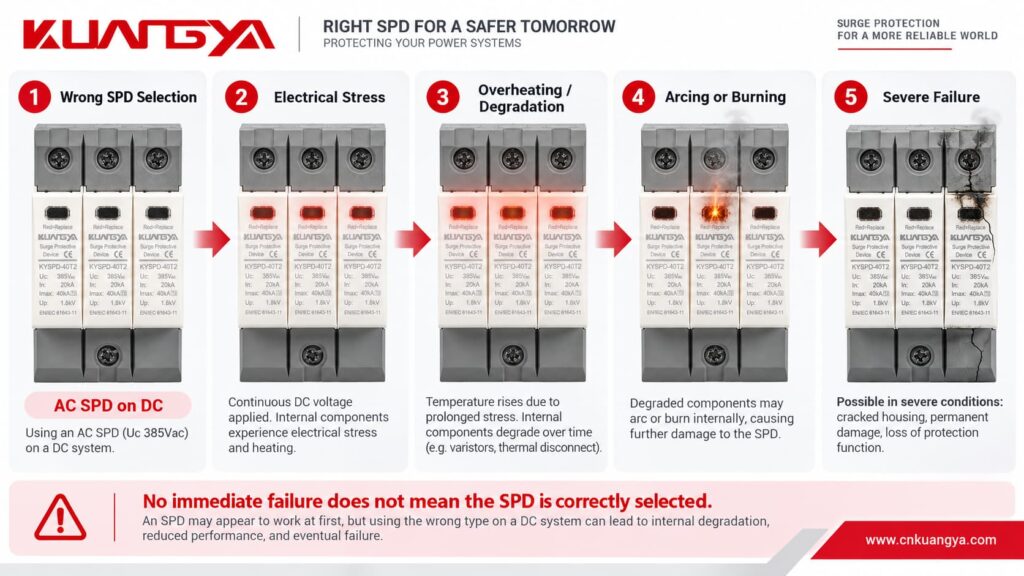
النقطة الأساسية هي:
عدم حدوث فشل فوري لا يعني أن جهاز الحماية من اندفاع التيار (SPD) قد تم اختياره بشكل صحيح.
قد يظل جهاز الحماية من اندفاع التيار (SPD) المطبق بشكل خاطئ مثبتاً لأسابيع أو أشهر قبل أن يتسبب اندفاع التيار، أو تغير درجة الحرارة، أو حالة الشبكة، أو مشكلة العزل، أو تدهور المكونات في حدوث فشل.
شاهد: ماذا يحدث عند استخدام جهاز حماية من اندفاع التيار (SPD) خاطئ في نظام تيار مستمر (DC)؟
هذا السؤال يحتاج إلى إجابة دقيقة.
توصيل جهاز حماية من اندفاع التيار المتردد (AC SPD) بتيار مستمر (DC) لا يعني أنه سينفجر على الفور.
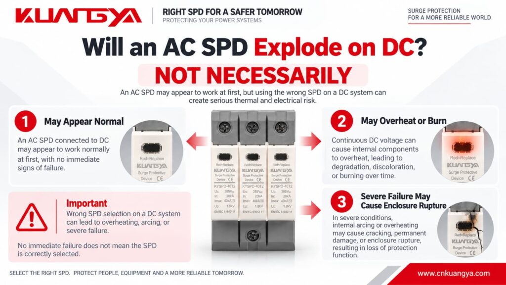
في العديد من التركيبات غير الصحيحة، لا يحدث شيء دراماتيكي على الفور.
القلق الحقيقي هو ما يحدث عندما يتعرض جهاز الحماية لإجهاد كهربائي أو حراري.
قد يبدو تسلسل الفشل المبسط كما يلي:
اختيار غير صحيح لجهاز الحماية ← إجهاد كهربائي مفرط ← تسخين أو تدهور ← زيادة تيار التسريب أو تيار العطل ← صعوبة في الفصل ← حدوث قوس كهربائي أو احتراق ← احتمال تمزق الغلاف الخارجي.
لذلك، القول بأن:
“جهاز الحماية من اندفاع التيار المتردد (AC SPD) سينفجر إذا تم توصيله بتيار مستمر (DC).”
هي عبارة مطلقة أكثر من اللازم.
العبارة الأكثر دقة من الناحية الفنية هي:
إن استخدام جهاز حماية من اندفاع التيار (SPD) غير مصنف لتطبيقات التيار المستمر قد يؤدي إلى خطر حدوث ارتفاع شديد في درجة الحرارة ونشوب حريق. وفي ظل ظروف الأعطال الشديدة، قد يحترق الجهاز أو يتمزق غلافه الخارجي.
“غالباً ما تُستخدم كلمة ”انفجار" بشكل غير رسمي لوصف جهاز الحماية التالف أو المتمزق، ولكن التمزق العنيف للغلاف الخارجي هو وصف تقني أكثر دقة.
إذا كان جهاز الحماية مثبتاً بالفعل وتشعر بالقلق من احتمال تعرضه للتلف، راجع دليلنا حول كيفية معرفة ما إذا كان جهاز الحماية من اندفاع التيار تالفاً.
تستخدم العديد من أجهزة الحماية من زيادة التيار (SPDs) مقاومات متغيرة بأكسيد المعدن، والتي تُعرف عادةً باسم (MOVs).
During normal operation, a correctly selected MOV-based SPD has very low leakage current.
During a transient overvoltage, the MOV becomes conductive and diverts surge current.
After the surge disappears, it should return to its high-resistance state.
However, repeated surge events, temporary overvoltage, excessive continuous voltage, aging, or incorrect application can gradually degrade the MOV.
As degradation progresses, leakage current may increase.
More leakage current creates more heat.
More heat may cause additional degradation.
This process can eventually result in thermal runaway if the device is not safely disconnected.
Modern SPDs therefore commonly include a thermal disconnection mechanism designed to isolate an overloaded MOV.
In a DC application, that disconnection mechanism must also be capable of safely dealing with the DC conditions that appear when the device disconnects.
Imagine two contacts beginning to separate while current is flowing.
As the gap becomes larger, an electrical arc can form between them.
In AC, the current naturally passes through zero periodically. This can assist arc extinction.
In DC, there is no equivalent natural current zero during normal operation.
The arc can therefore continue unless the device has been designed with an appropriate method to interrupt it.
This principle is not limited to SPDs.
It is also one reason why DC circuit breakers, DC isolators, contactors, and fuses need appropriate DC ratings.
The same general rule applies:
Never assume an AC electrical device is suitable for DC only because the voltage appears similar.
If you also want to understand how a typical power SPD is connected in the circuit, see our guide on why an SPD is connected in parallel instead of series.
لا يوجد.
Voltage is only one part of SPD selection.
For a photovoltaic DC SPD, several parameters need to be considered together.
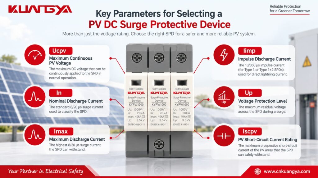
Ucpv is one of the most important parameters on a PV SPD.
It indicates the maximum DC voltage that may be continuously applied to the SPD under the specified conditions.
The selected Ucpv must be suitable for the highest voltage that can actually appear from the PV array.
Do not simply use the inverter’s nominal voltage.
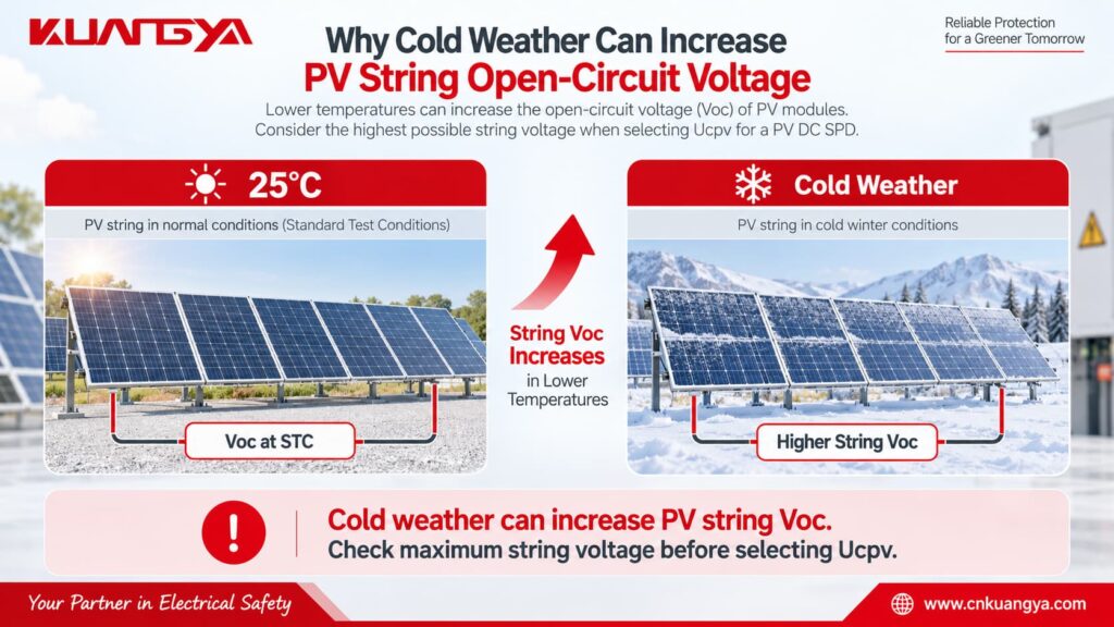
PV module open-circuit voltage increases when temperature decreases, so the maximum string voltage can be higher on a cold day than the value calculated from nominal operating voltage.
A simplified engineering calculation is:
Voc,max = Ns × Voc,STC × [1 + |βVoc| × (25°C − Tmin)]
أين:
Voc,max = estimated maximum string open-circuit voltage
Ns = number of modules connected in series
Voc,STC = module open-circuit voltage at STC
βVoc = module Voc temperature coefficient expressed per °C
Tmin = minimum design temperature at the installation site
This simplified formula assumes the manufacturer’s temperature coefficient is applicable over the temperature range being considered.
For an actual project, always follow the PV module manufacturer’s calculation method and applicable electrical design requirements.
The important selection relationship is:
Ucpv ≥ maximum PV voltage that can continuously appear at the SPD
A safety margin or additional design factor may also be required by the applicable standard, manufacturer, or project specification.
In is the nominal discharge current that the SPD can withstand repeatedly under the specified test waveform.
For Type 2 SPDs, the commonly used test waveform is 8/20 μs.
A higher In generally indicates greater repetitive surge-current capability, but In should never be considered alone.
Imax is the maximum value of the 8/20 μs surge current that a Type 2 SPD can discharge under its specified test conditions.
It describes a maximum capability rather than normal repetitive operation.
Iimp is particularly important for Type 1 SPDs.
It is associated with the 10/350 μs lightning-current waveform and is used when the SPD may need to handle partial lightning current.
Up indicates the voltage protection level provided by the SPD during surge discharge.
A lower Up can provide better voltage limitation, but it still needs to be coordinated with the protected equipment and the rest of the surge protection system.
The SPD should limit the surge to a level compatible with the impulse withstand capability of the equipment being protected.
Iscpv is especially important for photovoltaic SPDs.
It represents the maximum prospective PV DC short-circuit current for which the SPD’s end-of-life and disconnection behavior has been evaluated.
The SPD must be suitable for the prospective short-circuit current available at the installation point.
This is another reason why choosing a PV SPD only by voltage is not enough.
Quick Check: Use the simple tool below to see whether the basic SPD application type and voltage marking appear compatible with your system.
Select the system type and the marking shown on the SPD. This quick check only evaluates basic AC/DC application compatibility and does not replace a full technical selection.
For PV systems, enter the maximum expected DC operating voltage rather than only the nominal inverter voltage.
إخلاء مسؤولية: This tool is for preliminary selection only. Always verify the SPD datasheet, system configuration, maximum operating voltage, short-circuit conditions, and applicable standards before installation.
This is one of the most common misunderstandings.
Suppose two SPDs are placed next to each other.
One says:
Uc: 1000V AC
The other says:
Ucpv: 1000 فولت تيار مستمر
Both contain the number “1000V,” but that does not make them interchangeable.
Their application ratings, test conditions, internal arrangement, insulation design, disconnection behavior, and applicable standards may be different.
Always read the complete marking.
Never remove “AC,” “DC,” or “PV” from the voltage specification when comparing products.
The differences are easier to understand when they are compared directly.
| الميزة | AC SPD | التيار المستمر الكهروضوئي |
|---|---|---|
| Main application | AC power distribution | DC side of PV systems |
| Supply | مكيف الهواء | العاصمة |
| Natural zero crossing | نعم | لا يوجد |
| Typical voltage marking | Uc AC | Ucpv / Uc DC |
| DC fault interruption | Not assumed unless specified | Designed/tested for stated DC application |
| Common installation | Main distribution board, sub-panel | Combiner box, PV DC distribution, inverter DC side |
| Relevant IEC product standard | IEC 61643-11 | IEC 61643-31 |
| أقصى جهد للنظام | According to AC rating | According to specified PV DC rating |
| PV short-circuit consideration | Not a PV rating | Iscpv may be specified |
| Typical protection types | Type 1, Type 1+2, Type 2 | PV Type 1, Type 1+2, Type 2 |
The most important difference is not the appearance of the product.
It is what electrical system the SPD has actually been designed, rated, and tested for.
The same principle works in reverse.
Do not assume a DC SPD can be installed on AC simply because its DC voltage rating is higher than the AC system voltage.
على سبيل المثال:
A 1000V DC PV SPD is not automatically suitable for a 230V or 400V AC distribution board.
The manufacturer must provide an appropriate AC rating for that application.
If the device has both AC and DC ratings, follow the relevant rating for the system being protected.
If it is marked only as a PV DC SPD, use it only for the application specified by the manufacturer.
Not unless the manufacturer specifically provides a DC rating that covers that DC circuit.
A label such as:
Uc = 275V AC
does not mean:
275V DC
and certainly does not mean the device can be used on a 600V, 1000V, or 1500V PV system.
This is particularly important because 275V AC Type 2 SPDs are very common in low-voltage AC distribution systems.
Their familiar appearance can lead to incorrect use in DC equipment.
Always check the complete specification.
A better selection process starts with the electrical system, not with the SPD catalogue.
First determine where the SPD will be installed.
على سبيل المثال:
PV modules → DC combiner box → DC cables → inverter DC input → inverter AC output
The SPD installed before the inverter on the PV side is protecting a DC circuit.
The SPD installed on the inverter's AC output is protecting an AC circuit.
These two locations normally require different SPD specifications.
If your inverter already includes surge protection, see our guide on whether a solar inverter with a built-in SPD still needs an external SPD.
Check the number of modules in series, module Voc, temperature coefficient, and minimum expected module temperature.
Do not rely only on the inverter's nominal operating voltage.
Cold weather can increase the open-circuit voltage of a PV string.
The selected Ucpv must be suitable for the highest expected PV voltage.
The appropriate SPD type depends on the lightning protection concept and installation.
A Type 2 PV SPD is widely used for protection against induced and switching surges.
A Type 1 or Type 1+2 SPD may be required where partial lightning current has to be handled, depending on the installation and lightning protection design.
Do not choose Type 1, Type 1+2, or Type 2 based only on the kA number printed on the front.
After confirming the voltage and SPD type, compare the discharge-current parameters and voltage protection level.
For a Type 2 SPD, In and Imax are especially relevant.
For a Type 1 or Type 1+2 SPD, Iimp is also important.
Up should be coordinated with the impulse withstand level of the equipment being protected.
The prospective short-circuit current at the installation point also matters.
Check whether the SPD's Iscpv is suitable for the PV source.
Also confirm the system configuration and the required protection modes between positive, negative, and PE.
For dedicated photovoltaic DC SPDs, look for documentation relevant to PV DC applications, such as IEC 61643-31 compliance where applicable.
Do not rely solely on the product's external appearance.
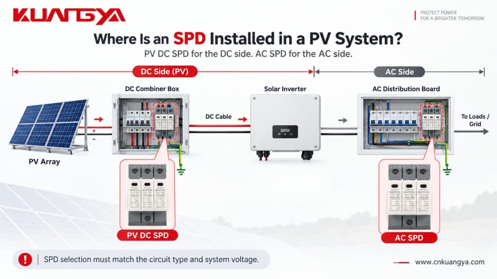
Common locations include the DC combiner box and the DC input side of the inverter.
In a larger PV system, protection may be required at more than one location depending on cable length, lightning protection design, equipment withstand level, and installation conditions.
The distance between the SPD and the protected inverter also matters.
Long connection conductors add inductive voltage during a surge, which can increase the effective voltage seen by the protected equipment.
Therefore, the SPD should not only be correctly selected — it should also be installed with short, direct connection conductors wherever possible.
If you want to understand this part in more detail, see:
هل المسافة بين جهاز الحماية من اندفاع التيار (SPD) والعاكس (Inverter) مهمة؟
لا يوجد.
This is another common misunderstanding.
An incorrectly selected AC SPD installed on a DC system may not fail immediately.
Under normal conditions, the SPD is usually in a high-impedance standby state.
That means the installation can appear to operate normally even though the SPD is not correctly rated for the application.
The real problem may appear only when:
a strong surge occurs, the MOV ages, leakage current increases, the SPD experiences a temporary overvoltage, the device reaches end of life, or the thermal disconnector needs to operate.
بناءً على ذلك:
“It has not failed yet” is not proof that an SPD is correctly selected.
Check its ratings instead.
A common mistake is using an AC SPD on a DC system simply because the voltage number printed on the device appears to match. Other common mistakes include ignoring the AC/DC marking, assuming a higher voltage rating automatically makes an SPD safer, ignoring the maximum PV open-circuit voltage in cold conditions, overlooking Iscpv, choosing an SPD only by Imax, and assuming a green status window proves that the SPD is correct for the application.
A green indicator normally tells you something about the current mechanical or electrical status of the protection module.
It does لا prove that the model was correctly selected for the system.
Before installing an SPD, answer these questions:
| تحقق | سؤال |
|---|---|
| نظام | Is the circuit AC or DC? |
| التطبيق | Is it specifically a PV circuit? |
| الفولتية | What is the maximum continuous system voltage? |
| SPD rating | Is Uc or Ucpv suitable for that voltage? |
| SPD type | Type 1, Type 1+2, or Type 2? |
| Surge current | Are In, Imax and/or Iimp appropriate? |
| Protection level | Is Up coordinated with the equipment? |
| Short-circuit capability | Is Iscpv suitable for the PV source? |
| التكوين | Does the connection arrangement match the PV system? |
| قياسي | Is the SPD designed and tested for the intended application? |
If any of these points are unclear, check the manufacturer's datasheet before energizing the circuit.
Only if the manufacturer specifically provides a DC rating for the device and that rating is suitable for the DC system. An SPD marked only for AC operation should not automatically be used on a DC circuit.
Not necessarily. It may initially appear to operate normally. However, an incorrectly rated SPD can overheat or fail to disconnect safely under abnormal conditions. Severe failure may result in arcing, burning, fire, or enclosure rupture.
No. A 275V AC rating does not make the device suitable for a 600V DC PV system. Use an SPD specifically rated for the required DC voltage and PV application.
Do not assume that you can. The identical voltage number does not mean the application ratings are equivalent. Check whether the manufacturer explicitly provides an appropriate 1000V DC rating.
Uc generally refers to maximum continuous operating voltage. For photovoltaic applications, Ucpv specifically identifies the maximum continuous DC voltage applicable to the PV SPD. The selected value must be suitable for the highest PV voltage that can occur at the installation.
The SPD may be subjected to excessive continuous electrical stress. This can increase leakage current, accelerate degradation, cause overheating, and eventually trigger or damage the disconnection mechanism.
لا يوجد.
Ucpv must be high enough for the PV system, but SPD selection is a balance between continuous operating voltage and protection performance.
You should also consider Up, discharge-current ratings, equipment withstand voltage, system configuration, and manufacturer recommendations.
Check the product label and datasheet.
Look for clear markings such as:
275V AC
جهد التشغيل المستمر الأقصى 440 فولت تيار متردد
جهد التشغيل المستمر الأقصى لنظام الطاقة الشمسية 1000 فولت تيار مستمر
Ucpv 1500V DC
Also check the applicable product standard and wiring configuration.
Never identify an AC or DC SPD only by its shape or number of poles.
An AC SPD and a DC SPD may look almost identical, but that does not mean they can be used interchangeably.
The biggest mistake is choosing an SPD only by the voltage number printed on the front.
A 1000V rating does not tell the whole story.
You also need to know whether the rating applies to AC or DC, whether the SPD is suitable for photovoltaic use, its maximum continuous operating voltage, discharge-current capability, voltage protection level, short-circuit capability, system configuration, and applicable standard.
Using an AC SPD on a DC system does not mean it will immediately explode, but the device must have a suitable DC rating for the application.
However, an SPD that is not designed for the DC application may experience excessive stress and may not disconnect safely at the end of its life. This can lead to overheating, sustained arcing, burning, fire, and in severe cases enclosure rupture.
For a photovoltaic DC system, use a surge protective device specifically designed and rated for the PV DC application.
KUANGYA provides DC surge protection solutions for different photovoltaic system voltages, including 600V DC, 1000V DC, and 1500V DC applications, with different SPD configurations available for solar PV protection.

