温州市岳陽工業区 325000
勤務時間
月曜日~金曜日:午前7時~午後7時
週末午前10時~午後5時
温州市岳陽工業区 325000
勤務時間
月曜日~金曜日:午前7時~午後7時
週末午前10時~午後5時

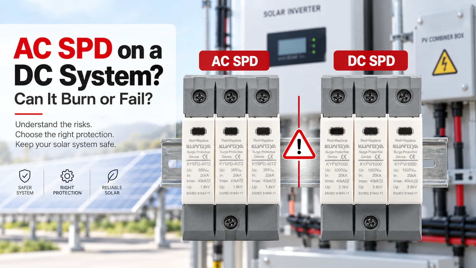
AC用SPDを DCシステムに使用することは、 そのデバイスがDC用途向けに特別に定格されていない場合、危険を伴う可能性があります。.
AC用SPDとDC用SPDは外見が非常に似ていることがありますが、自動的に互換性があるわけではありません。最も一般的な間違いの一つは、ラベルに記載された電圧のみを比較することです。例えば、SPDに「1000V」と記載されているのを見て、1000V DCの太陽光発電システムに設置できると判断してしまうケースがあります。.
そのような思い込みは危険です。.
SPDは、メーカーがそのDC用途向けに特別に定格を定めており、かつ電気的特性がシステムと一致している場合にのみ、DCシステムに設置してください。.
直流回路で交流専用のSPDを使用すると、過熱、内部遮断機構の故障、持続的なアーク放電、焼損、または火災を引き起こす可能性があります。深刻な故障の場合、SPDの筐体が破損することもあります。.
では、交流用SPDを直流に接続すると爆発するのでしょうか?
必ずしもそうとは限りません。しかし、不適切なSPDを使用すると重大な故障リスクが生じ、深刻な熱的または電気的故障により筐体が破損する可能性があります。.
電圧値が似ているという理由だけで、交流用SPDを直流システムに使用してはなりません。.
交流専用と表示された機器は、交流システムの条件に合わせて設計および試験されています。太陽光発電用直流SPDは、太陽光発電設備の直流側に見られる連続直流電圧、故障条件、システム構成、および遮断要件に合わせて設計されています。.
太陽光発電システムでは、常にSPDの定格全体を確認してください。特に以下の項目が重要です。 Ucpv、In、Imax、Iimp(該当する場合)、Up、Iscpv、SPDタイプ、接続構成、および適用規格.
通常、AC専用のSPDをDCシステムに使用してはなりません。.
重要な言葉は “「定格」です。”
メーカーが特定のSPDをACおよびDCの両方の用途に適していると明記している場合は、規定された定格および設置条件の範囲内で使用できます。.
ただし、AC専用と表示されたSPDをDC回路に自動的に取り付けてはなりません。.
例えば、こうだ:
| SPDの表示 | システム | 適合か? |
|---|---|---|
| Uc 275V AC | 600V DC 太陽光発電システム | いいえ |
| Uc 440V AC | 1000V DC 太陽光発電システム | いいえ |
| Ucpv 1000V DC | 定格内の適切な太陽光発電システム | 可能性がある |
| AC/DC両用SPD | 対応するACまたはDCシステム | メーカーの仕様を確認してください。 |
電圧の数値だけを確認するのでは不十分な理由はここにあります。.
1000V ACと1000V DCは、同じアプリケーション定格ではありません。.
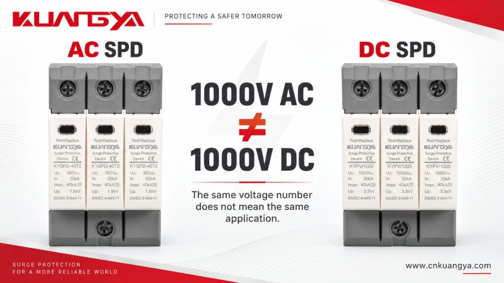
数値の後の文字が重要です。.
AC用SPDとDC用SPDはどちらも、過渡過電圧を制限し、サージ電流を敏感な機器から逃がすという基本的な役割は同じです。.
しかし、それらが動作する電気的環境は異なります。.
その違いは、異常状態時およびSPDの寿命末期において特に重要となります。.
通常の正弦波交流システムでは、瞬時電圧と電流は周期的にゼロを通過します。.
50Hzまたは60Hzの周波数では、これが毎秒繰り返し発生します。.
自然なゼロクロス点は、開閉装置や遮断装置が開放される際のアーク消弧を助ける役割を果たします。.
これが、交流の開閉や故障遮断用に設計された機器が、直流条件下でも安全に動作すると自動的に想定できない理由の一つです。.
直流電源は同じ極性を維持し、交流のように自然にゼロを通過することはありません。.
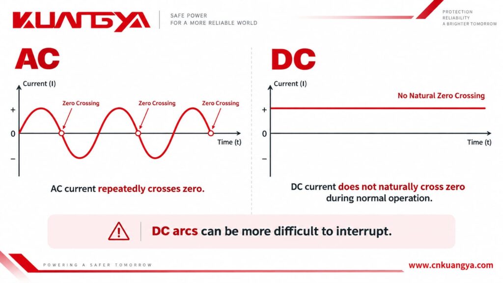
したがって、直流アークが発生した場合、その遮断はより困難になる可能性があります。.
太陽光発電システムにおいて、太陽光が当たっている間はソーラーアレイが直流電力を供給し続ける可能性があるため、この点は重要です。.
SPDが過負荷状態となり、内部の切り離しシステムが故障した保護コンポーネントを絶縁しなければならない場合、そのデバイスは直流条件下で安全に動作するように設計されていなければなりません。.
これが、専用のPV用直流SPDが直流用途向けに設計された構造や切り離し機構を採用している理由の一つです。.
フェニックス・コンタクト社も、直流システムは交流システムとは挙動が異なるため、以下のものが必要であると説明しています。 直流用途向けに設計されたサージ防護デバイス.
交流用SPDを直流システムに設置しても、直ちに目に見える故障が発生するとは限らず、単一の故障シーケンスが存在するわけでもありません。.
その結果は、SPDの設計、直流電圧、利用可能な電流、システム構成、温度、サージの履歴、およびSPDがどのように故障するかによって異なります。.
不適切に選定されたSPDは、当初は正常に見える場合があります。.
それこそが、この間違いを危険なものにしています。.
| 想定される状況 | 発生しうる事象 |
|---|---|
| 設置直後 | SPDは完全に正常に見える可能性がある |
| 継続的な過電圧ストレス | MOVやその他の保護コンポーネントが発熱する可能性がある |
| 部品の劣化 | 漏れ電流が増加する可能性がある |
| 熱過負荷 | 内部の熱遮断器が作動する可能性がある |
| 不適切な直流遮断 | 接点分離後もアークが継続する可能性がある |
| 重大な故障 | 焼損、発煙、または発火が発生する可能性がある |
| 致命的な故障 | ハウジングの亀裂や破損の可能性 |
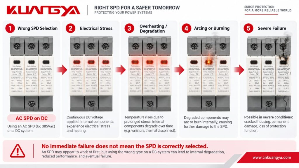
重要なポイントは以下の通りです:
直ちに故障しないからといって、そのSPDが正しく選定されているとは限りません。.
不適切に適用されたSPDは、サージ、温度変化、系統状態、絶縁不良、または部品の劣化によって故障が発生するまで、数週間から数ヶ月間設置されたままになる可能性があります。.
動画:直流(DC)システムで誤ったSPDを使用するとどうなるか?
この質問には慎重な回答が必要です。.
AC用SPDをDC回路に接続したからといって、即座に爆発するわけではありません。.
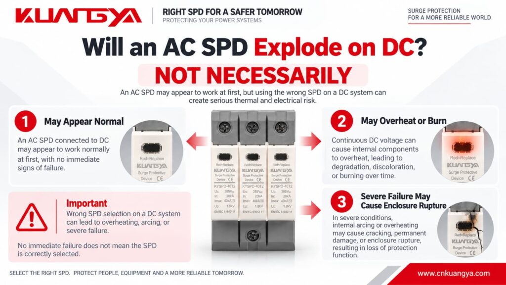
多くの不適切な設置事例では、直ちに劇的な事象が発生するわけではありません。.
真の懸念は、SPDが電気的または熱的ストレスを受けた際に何が起こるかという点です。.
簡略化した故障のプロセスは以下の通りです:
不適切なSPDの選定 → 過度な電気的ストレス → 発熱または劣化 → 漏れ電流や故障電流の増大 → 遮断の困難化 → アーク放電または焼損 → 外郭の破損の可能性
したがって、次のように言えます:
“「AC用SPDをDC回路に接続すると爆発する」という表現は、”
あまりに断定的すぎます。.
より技術的に正確な記述は以下の通りです。
DC用途に適格でないSPDを使用すると、深刻な過熱や火災のリスクが生じる可能性があります。重大な故障条件下では、SPDが焼損したり、筐体が破損したりする恐れがあります。.
“「爆発」という言葉は、損傷または破損したSPDを指して日常的に使われることが多いですが、 筐体の激しい破損 という表現の方が、技術的にはより正確です。.
SPDがすでに設置されており、損傷している可能性があると懸念される場合は、以下のガイドをご覧ください。 SPDの故障を見分ける方法.
多くのSPDは、一般的にMOVと呼ばれる酸化亜鉛素子を使用しています。.
During normal operation, a correctly selected MOV-based SPD has very low leakage current.
During a transient overvoltage, the MOV becomes conductive and diverts surge current.
After the surge disappears, it should return to its high-resistance state.
However, repeated surge events, temporary overvoltage, excessive continuous voltage, aging, or incorrect application can gradually degrade the MOV.
As degradation progresses, leakage current may increase.
More leakage current creates more heat.
More heat may cause additional degradation.
This process can eventually result in thermal runaway if the device is not safely disconnected.
Modern SPDs therefore commonly include a thermal disconnection mechanism designed to isolate an overloaded MOV.
In a DC application, that disconnection mechanism must also be capable of safely dealing with the DC conditions that appear when the device disconnects.
Imagine two contacts beginning to separate while current is flowing.
As the gap becomes larger, an electrical arc can form between them.
In AC, the current naturally passes through zero periodically. This can assist arc extinction.
In DC, there is no equivalent natural current zero during normal operation.
The arc can therefore continue unless the device has been designed with an appropriate method to interrupt it.
This principle is not limited to SPDs.
It is also one reason why DC circuit breakers, DC isolators, contactors, and fuses need appropriate DC ratings.
The same general rule applies:
Never assume an AC electrical device is suitable for DC only because the voltage appears similar.
If you also want to understand how a typical power SPD is connected in the circuit, see our guide on why an SPD is connected in parallel instead of series.
そうだ。.
Voltage is only one part of SPD selection.
For a photovoltaic DC SPD, several parameters need to be considered together.
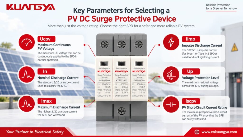
Ucpv is one of the most important parameters on a PV SPD.
It indicates the maximum DC voltage that may be continuously applied to the SPD under the specified conditions.
The selected Ucpv must be suitable for the highest voltage that can actually appear from the PV array.
Do not simply use the inverter’s nominal voltage.
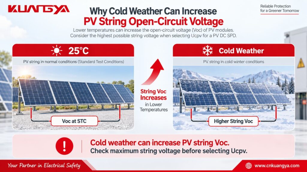
PV module open-circuit voltage increases when temperature decreases, so the maximum string voltage can be higher on a cold day than the value calculated from nominal operating voltage.
A simplified engineering calculation is:
Voc,max = Ns × Voc,STC × [1 + |βVoc| × (25°C − Tmin)]
どこでだ:
Voc,max = estimated maximum string open-circuit voltage
Ns = number of modules connected in series
Voc,STC = module open-circuit voltage at STC
βVoc = module Voc temperature coefficient expressed per °C
Tmin = minimum design temperature at the installation site
This simplified formula assumes the manufacturer’s temperature coefficient is applicable over the temperature range being considered.
For an actual project, always follow the PV module manufacturer’s calculation method and applicable electrical design requirements.
The important selection relationship is:
Ucpv ≥ maximum PV voltage that can continuously appear at the SPD
A safety margin or additional design factor may also be required by the applicable standard, manufacturer, or project specification.
In is the nominal discharge current that the SPD can withstand repeatedly under the specified test waveform.
For Type 2 SPDs, the commonly used test waveform is 8/20 μs.
A higher In generally indicates greater repetitive surge-current capability, but In should never be considered alone.
Imax is the maximum value of the 8/20 μs surge current that a Type 2 SPD can discharge under its specified test conditions.
It describes a maximum capability rather than normal repetitive operation.
Iimp is particularly important for Type 1 SPDs.
It is associated with the 10/350 μs lightning-current waveform and is used when the SPD may need to handle partial lightning current.
Up indicates the voltage protection level provided by the SPD during surge discharge.
A lower Up can provide better voltage limitation, but it still needs to be coordinated with the protected equipment and the rest of the surge protection system.
The SPD should limit the surge to a level compatible with the impulse withstand capability of the equipment being protected.
Iscpv is especially important for photovoltaic SPDs.
It represents the maximum prospective PV DC short-circuit current for which the SPD’s end-of-life and disconnection behavior has been evaluated.
The SPD must be suitable for the prospective short-circuit current available at the installation point.
This is another reason why choosing a PV SPD only by voltage is not enough.
Quick Check: Use the simple tool below to see whether the basic SPD application type and voltage marking appear compatible with your system.
Select the system type and the marking shown on the SPD. This quick check only evaluates basic AC/DC application compatibility and does not replace a full technical selection.
For PV systems, enter the maximum expected DC operating voltage rather than only the nominal inverter voltage.
免責事項 This tool is for preliminary selection only. Always verify the SPD datasheet, system configuration, maximum operating voltage, short-circuit conditions, and applicable standards before installation.
This is one of the most common misunderstandings.
Suppose two SPDs are placed next to each other.
One says:
Uc: 1000V AC
The other says:
Ucpv: 1000V DC
Both contain the number “1000V,” but that does not make them interchangeable.
Their application ratings, test conditions, internal arrangement, insulation design, disconnection behavior, and applicable standards may be different.
Always read the complete marking.
Never remove “AC,” “DC,” or “PV” from the voltage specification when comparing products.
The differences are easier to understand when they are compared directly.
| 特徴 | AC SPD | PV DC SPD |
|---|---|---|
| Main application | AC power distribution | DC side of PV systems |
| Supply | 交流 | DC |
| Natural zero crossing | はい | いいえ |
| Typical voltage marking | Uc AC | Ucpv / Uc DC |
| DC fault interruption | Not assumed unless specified | Designed/tested for stated DC application |
| Common installation | Main distribution board, sub-panel | Combiner box, PV DC distribution, inverter DC side |
| Relevant IEC product standard | IEC 61643-11 | IEC 61643-31 |
| 最大システム電圧 | According to AC rating | According to specified PV DC rating |
| PV short-circuit consideration | Not a PV rating | Iscpv may be specified |
| Typical protection types | Type 1, Type 1+2, Type 2 | PV Type 1, Type 1+2, Type 2 |
The most important difference is not the appearance of the product.
It is what electrical system the SPD has actually been designed, rated, and tested for.
The same principle works in reverse.
Do not assume a DC SPD can be installed on AC simply because its DC voltage rating is higher than the AC system voltage.
例えば、こうだ:
A 1000V DC PV SPD is not automatically suitable for a 230V or 400V AC distribution board.
The manufacturer must provide an appropriate AC rating for that application.
If the device has both AC and DC ratings, follow the relevant rating for the system being protected.
If it is marked only as a PV DC SPD, use it only for the application specified by the manufacturer.
Not unless the manufacturer specifically provides a DC rating that covers that DC circuit.
A label such as:
Uc = 275V AC
does not mean:
275V DC
and certainly does not mean the device can be used on a 600V, 1000V, or 1500V PV system.
This is particularly important because 275V AC Type 2 SPDs are very common in low-voltage AC distribution systems.
Their familiar appearance can lead to incorrect use in DC equipment.
Always check the complete specification.
A better selection process starts with the electrical system, not with the SPD catalogue.
First determine where the SPD will be installed.
例えば、こうだ:
PV modules → DC combiner box → DC cables → inverter DC input → inverter AC output
The SPD installed before the inverter on the PV side is protecting a DC circuit.
The SPD installed on the inverter's AC output is protecting an AC circuit.
These two locations normally require different SPD specifications.
If your inverter already includes surge protection, see our guide on whether a solar inverter with a built-in SPD still needs an external SPD.
Check the number of modules in series, module Voc, temperature coefficient, and minimum expected module temperature.
Do not rely only on the inverter's nominal operating voltage.
Cold weather can increase the open-circuit voltage of a PV string.
The selected Ucpv must be suitable for the highest expected PV voltage.
The appropriate SPD type depends on the lightning protection concept and installation.
A Type 2 PV SPD is widely used for protection against induced and switching surges.
A Type 1 or Type 1+2 SPD may be required where partial lightning current has to be handled, depending on the installation and lightning protection design.
Do not choose Type 1, Type 1+2, or Type 2 based only on the kA number printed on the front.
After confirming the voltage and SPD type, compare the discharge-current parameters and voltage protection level.
For a Type 2 SPD, In and Imax are especially relevant.
For a Type 1 or Type 1+2 SPD, Iimp is also important.
Up should be coordinated with the impulse withstand level of the equipment being protected.
The prospective short-circuit current at the installation point also matters.
Check whether the SPD's Iscpv is suitable for the PV source.
Also confirm the system configuration and the required protection modes between positive, negative, and PE.
For dedicated photovoltaic DC SPDs, look for documentation relevant to PV DC applications, such as IEC 61643-31 compliance where applicable.
Do not rely solely on the product's external appearance.
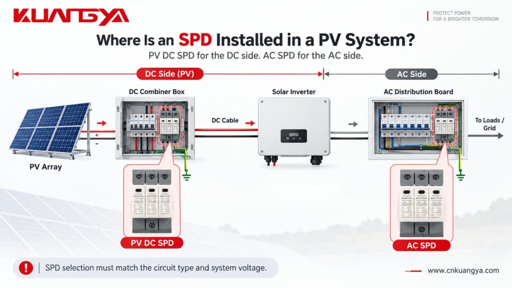
Common locations include the DC combiner box and the DC input side of the inverter.
In a larger PV system, protection may be required at more than one location depending on cable length, lightning protection design, equipment withstand level, and installation conditions.
The distance between the SPD and the protected inverter also matters.
Long connection conductors add inductive voltage during a surge, which can increase the effective voltage seen by the protected equipment.
Therefore, the SPD should not only be correctly selected — it should also be installed with short, direct connection conductors wherever possible.
If you want to understand this part in more detail, see:
そうだ。.
This is another common misunderstanding.
An incorrectly selected AC SPD installed on a DC system may not fail immediately.
Under normal conditions, the SPD is usually in a high-impedance standby state.
That means the installation can appear to operate normally even though the SPD is not correctly rated for the application.
The real problem may appear only when:
a strong surge occurs, the MOV ages, leakage current increases, the SPD experiences a temporary overvoltage, the device reaches end of life, or the thermal disconnector needs to operate.
Therefore:
“It has not failed yet” is not proof that an SPD is correctly selected.
Check its ratings instead.
A common mistake is using an AC SPD on a DC system simply because the voltage number printed on the device appears to match. Other common mistakes include ignoring the AC/DC marking, assuming a higher voltage rating automatically makes an SPD safer, ignoring the maximum PV open-circuit voltage in cold conditions, overlooking Iscpv, choosing an SPD only by Imax, and assuming a green status window proves that the SPD is correct for the application.
A green indicator normally tells you something about the current mechanical or electrical status of the protection module.
It does ない prove that the model was correctly selected for the system.
Before installing an SPD, answer these questions:
| チェック | 質問 |
|---|---|
| システム | Is the circuit AC or DC? |
| 申し込み | Is it specifically a PV circuit? |
| 電圧 | What is the maximum continuous system voltage? |
| SPD rating | Is Uc or Ucpv suitable for that voltage? |
| SPDタイプ | Type 1, Type 1+2, or Type 2? |
| Surge current | Are In, Imax and/or Iimp appropriate? |
| Protection level | Is Up coordinated with the equipment? |
| Short-circuit capability | Is Iscpv suitable for the PV source? |
| 構成 | Does the connection arrangement match the PV system? |
| スタンダード | Is the SPD designed and tested for the intended application? |
If any of these points are unclear, check the manufacturer's datasheet before energizing the circuit.
Only if the manufacturer specifically provides a DC rating for the device and that rating is suitable for the DC system. An SPD marked only for AC operation should not automatically be used on a DC circuit.
Not necessarily. It may initially appear to operate normally. However, an incorrectly rated SPD can overheat or fail to disconnect safely under abnormal conditions. Severe failure may result in arcing, burning, fire, or enclosure rupture.
No. A 275V AC rating does not make the device suitable for a 600V DC PV system. Use an SPD specifically rated for the required DC voltage and PV application.
Do not assume that you can. The identical voltage number does not mean the application ratings are equivalent. Check whether the manufacturer explicitly provides an appropriate 1000V DC rating.
Uc generally refers to maximum continuous operating voltage. For photovoltaic applications, Ucpv specifically identifies the maximum continuous DC voltage applicable to the PV SPD. The selected value must be suitable for the highest PV voltage that can occur at the installation.
The SPD may be subjected to excessive continuous electrical stress. This can increase leakage current, accelerate degradation, cause overheating, and eventually trigger or damage the disconnection mechanism.
そうだ。.
Ucpv must be high enough for the PV system, but SPD selection is a balance between continuous operating voltage and protection performance.
You should also consider Up, discharge-current ratings, equipment withstand voltage, system configuration, and manufacturer recommendations.
Check the product label and datasheet.
Look for clear markings such as:
275V AC
Uc 440V AC
Ucpv 1000V DC
Ucpv 1500V DC
Also check the applicable product standard and wiring configuration.
Never identify an AC or DC SPD only by its shape or number of poles.
An AC SPD and a DC SPD may look almost identical, but that does not mean they can be used interchangeably.
The biggest mistake is choosing an SPD only by the voltage number printed on the front.
A 1000V rating does not tell the whole story.
You also need to know whether the rating applies to AC or DC, whether the SPD is suitable for photovoltaic use, its maximum continuous operating voltage, discharge-current capability, voltage protection level, short-circuit capability, system configuration, and applicable standard.
Using an AC SPD on a DC system does not mean it will immediately explode, but the device must have a suitable DC rating for the application.
However, an SPD that is not designed for the DC application may experience excessive stress and may not disconnect safely at the end of its life. This can lead to overheating, sustained arcing, burning, fire, and in severe cases enclosure rupture.
For a photovoltaic DC system, use a surge protective device specifically designed and rated for the PV DC application.
KUANGYA provides DC surge protection solutions for different photovoltaic system voltages, including 600V DC, 1000V DC, and 1500V DC applications, with different SPD configurations available for solar PV protection.

