Zone industrielle WengYang Yueqing Wenzhou 325000
Heures de travail
Du lundi au vendredi : de 7h00 à 19h00
Le week-end : 10H00 - 17H00
Zone industrielle WengYang Yueqing Wenzhou 325000
Heures de travail
Du lundi au vendredi : de 7h00 à 19h00
Le week-end : 10H00 - 17H00

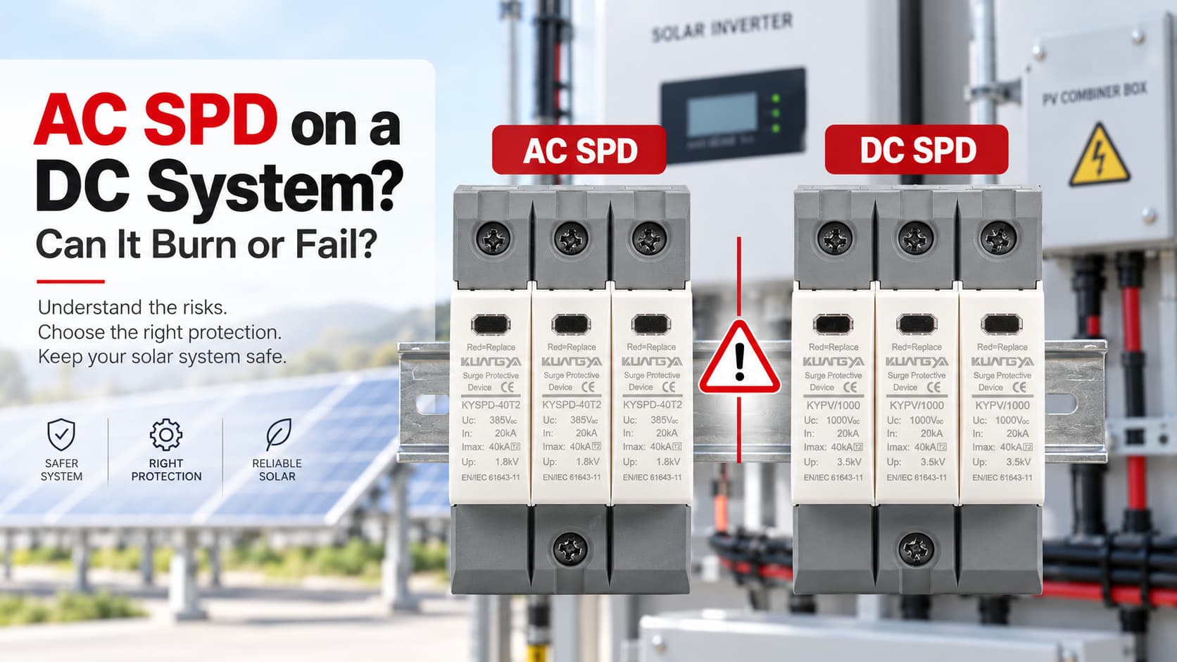
Utiliser un parafoudre AC sur un système DC peut être dangereux si l'appareil n'est pas spécifiquement conçu pour l'application DC.
Un parafoudre AC et un parafoudre DC peuvent paraître très similaires de l'extérieur, mais ils ne sont pas automatiquement interchangeables. L'une des erreurs les plus courantes consiste à comparer uniquement la tension indiquée sur l'étiquette. Par exemple, quelqu'un peut voir “ 1000V ” sur un parafoudre et supposer qu'il peut être installé dans un système solaire DC de 1000V.
Cette supposition peut être dangereuse.
Un parafoudre ne doit être installé sur un système DC que lorsque le fabricant l'a spécifiquement homologué pour cette application DC et que ses caractéristiques électriques correspondent au système.
L'utilisation d'un parafoudre (SPD) uniquement pour courant alternatif (AC) sur un circuit à courant continu (DC) peut provoquer une surchauffe, une défaillance du mécanisme de déconnexion interne, un arc électrique soutenu, une combustion ou un incendie. En cas de défaillance grave, le boîtier du parafoudre peut également se rompre.
Alors, un parafoudre AC peut-il exploser lorsqu'il est connecté à du DC ?
Pas nécessairement. Mais l'utilisation d'un parafoudre inadapté peut créer un risque de défaillance grave, et une défaillance thermique ou électrique sévère peut entraîner la rupture du boîtier.
Un parafoudre AC ne doit pas être utilisé sur un système DC simplement parce que la valeur de tension semble similaire.
Un appareil marqué uniquement pour un fonctionnement en AC a été conçu et testé pour les conditions des systèmes AC. Un parafoudre DC photovoltaïque est conçu pour la tension continue, les conditions de défaut, la configuration du système et les exigences de déconnexion rencontrées du côté DC d'une installation PV.
Pour les systèmes PV, vérifiez toujours les caractéristiques complètes du parafoudre, en particulier : Ucpv, In, Imax, Iimp le cas échéant, Up, Iscpv, type de parafoudre, configuration de connexion et norme applicable..
Normalement, vous ne devez pas utiliser un parafoudre (SPD) AC uniquement sur un système DC.
Le mot important est “ assigné ”.”
Si un fabricant précise clairement qu'un parafoudre particulier est adapté aux applications AC et DC, il peut être utilisé dans le respect des caractéristiques assignées et des conditions d'installation indiquées.
Cependant, un parafoudre marqué uniquement pour une utilisation en AC ne doit pas être installé automatiquement sur un circuit DC.
Par exemple :
| Marquage du parafoudre | Système | Adapté ? |
|---|---|---|
| Uc 275V AC | Système photovoltaïque 600V DC | Non |
| Uc 440V AC | Système photovoltaïque 1000V DC | Non |
| Ucpv 1000V DC | Système photovoltaïque adapté selon les caractéristiques nominales | Potentiellement oui |
| Parafoudre à double tension nominale AC/DC | Système AC ou DC correspondant | Vérifier les spécifications du fabricant |
C'est pourquoi la lecture de la valeur de tension seule ne suffit pas.
1000V AC et 1000V DC ne correspondent pas à la même application nominale.
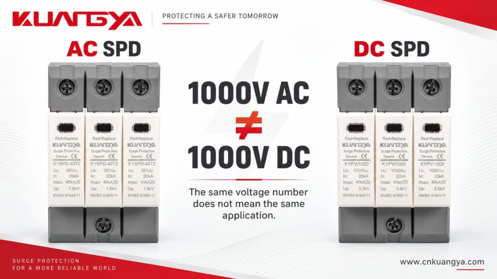
Les lettres suivant le chiffre ont leur importance.
Les parafoudres AC et DC remplissent la même fonction de base : ils aident à limiter les surtensions transitoires et à dériver le courant de foudre loin des équipements sensibles.
Mais les environnements électriques dans lesquels ils fonctionnent sont différents.
Cette différence devient particulièrement importante dans des conditions anormales et à la fin de la durée de vie du parafoudre (SPD).
Dans un système à courant alternatif sinusoïdal normal, la tension et le courant instantanés passent périodiquement par zéro.
À 50 Hz ou 60 Hz, cela se produit de manière répétée chaque seconde.
Les passages naturels par zéro peuvent aider à éteindre un arc lorsqu'un dispositif de commutation ou de déconnexion s'ouvre.
C'est l'une des raisons pour lesquelles on ne peut pas supposer automatiquement que l'équipement conçu pour la commutation et l'interruption de défaut en courant alternatif fonctionnera en toute sécurité dans des conditions de courant continu.
Une source de courant continu maintient la même polarité et ne passe pas naturellement par zéro de la même manière que le courant alternatif.
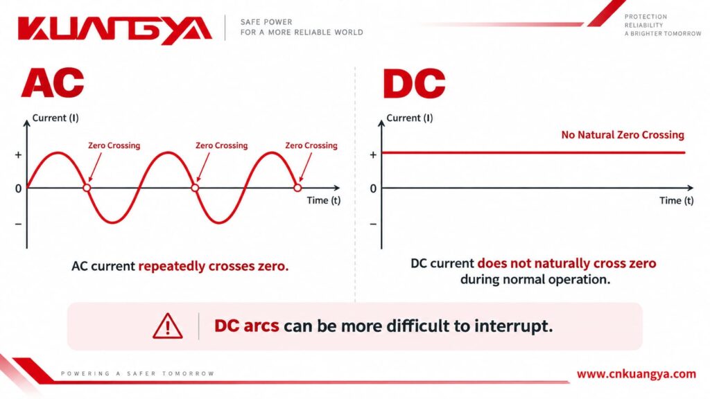
Si un arc électrique en courant continu se forme, il peut donc être plus difficile à interrompre.
Ceci est important dans les systèmes photovoltaïques car le champ solaire peut continuer à fournir une alimentation en courant continu tant que la lumière du soleil est disponible.
Si un parafoudre est surchargé et que son système de déconnexion interne doit isoler le composant de protection défaillant, le dispositif doit être conçu pour gérer les conditions de courant continu en toute sécurité.
C'est l'une des raisons pour lesquelles les parafoudres CC dédiés au photovoltaïque utilisent des conceptions et des dispositifs de déconnexion destinés aux applications en courant continu.
Phoenix Contact explique également que les systèmes CC se comportent différemment des systèmes CA et nécessitent donc des parafoudres conçus pour les applications en courant continu.
L'installation d'un parafoudre CA sur un système CC peut ne pas provoquer de défaillance visible immédiate, et il n'existe pas de séquence de défaillance unique.
Le résultat dépend de la conception du parafoudre, de la tension continue, du courant disponible, de la configuration du système, de la température, de l'historique des surtensions et de la manière dont le parafoudre tombe en panne.
Un parafoudre mal sélectionné peut sembler normal au premier abord.
C'est ce qui rend cette erreur dangereuse.
| Condition possible | Ce qui peut arriver |
|---|---|
| Immédiatement après l'installation | Le parafoudre peut sembler tout à fait normal |
| Contrainte de surtension continue | La varistance (MOV) ou d'autres composants de protection peuvent chauffer |
| Dégradation des composants | Le courant de fuite peut augmenter |
| Surcharge thermique | Le disjoncteur thermique interne peut se déclencher |
| Coupure CC inappropriée | Un arc peut se maintenir après le début de la séparation |
| Défaillance grave | Risque de brûlure, de fumée ou d'incendie |
| Défaillance extrême | Le boîtier peut se fissurer ou se rompre |
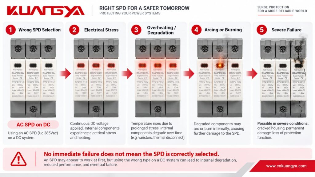
Le point clé est :
L'absence de défaillance immédiate ne signifie pas que le parafoudre est correctement sélectionné.
Un parafoudre mal appliqué peut rester installé pendant des semaines ou des mois avant qu'une surtension, un changement de température, une condition du réseau, un problème d'isolation ou une dégradation des composants ne provoque une défaillance.
Regardez : Que se passe-t-il lorsqu'un mauvais parafoudre est utilisé sur un système CC ?
Cette question nécessite une réponse prudente.
Raccorder un parafoudre AC à un circuit DC ne signifie pas qu'il explosera instantanément.
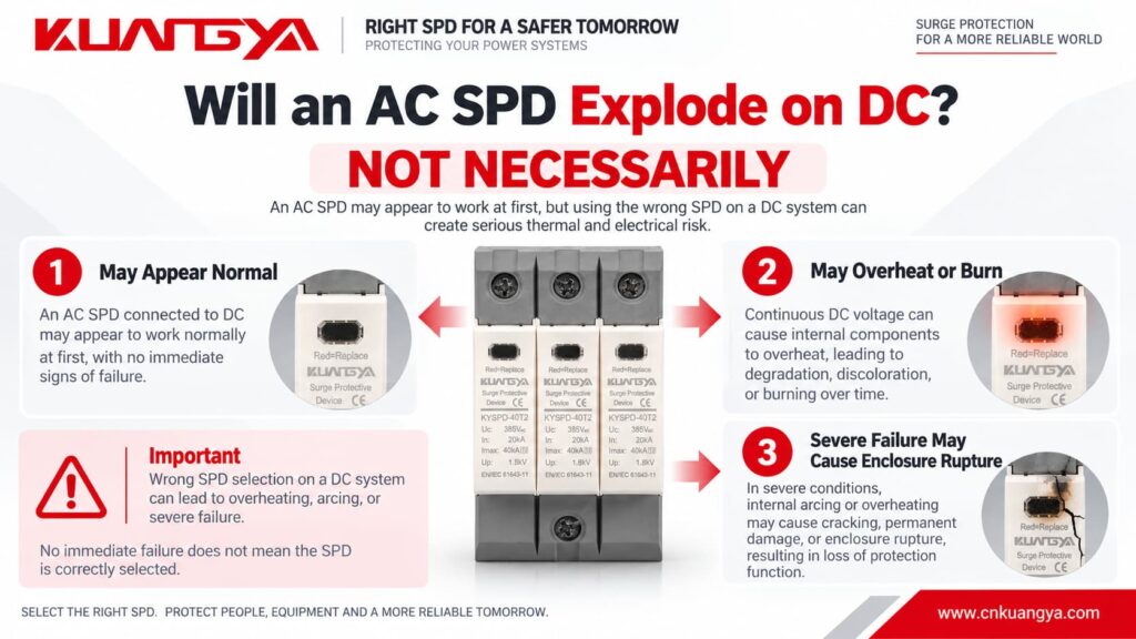
Dans de nombreuses installations incorrectes, rien de dramatique ne se produit immédiatement.
La véritable préoccupation est ce qui se passe lorsque le parafoudre subit une contrainte électrique ou thermique.
Une séquence de défaillance simplifiée peut se présenter comme suit :
Sélection incorrecte du parafoudre → contrainte électrique excessive → échauffement ou dégradation → augmentation du courant de fuite ou de défaut → difficulté de déconnexion → arc électrique ou combustion → rupture possible de l'enveloppe
Par conséquent, dire :
“ Un parafoudre CA explosera s'il est connecté à du courant continu. ”
est trop catégorique.
Une déclaration techniquement plus précise est :
L'utilisation d'un parafoudre non dimensionné pour une application en courant continu peut créer un risque sérieux de surchauffe et d'incendie. Dans des conditions de défaut sévères, le parafoudre peut brûler ou son boîtier peut se rompre.
“Le terme ” explosion » est souvent utilisé de manière informelle pour décrire un parafoudre endommagé ou rompu, mais une rupture violente du boîtier est une description technique plus précise.
Si un parafoudre est déjà installé et que vous craignez qu'il ait été endommagé, consultez notre guide sur comment savoir si un parafoudre est défectueux.
De nombreux parafoudres utilisent des varistances à oxyde métallique, communément appelées MOV.
During normal operation, a correctly selected MOV-based SPD has very low leakage current.
During a transient overvoltage, the MOV becomes conductive and diverts surge current.
After the surge disappears, it should return to its high-resistance state.
However, repeated surge events, temporary overvoltage, excessive continuous voltage, aging, or incorrect application can gradually degrade the MOV.
As degradation progresses, leakage current may increase.
More leakage current creates more heat.
More heat may cause additional degradation.
This process can eventually result in thermal runaway if the device is not safely disconnected.
Modern SPDs therefore commonly include a thermal disconnection mechanism designed to isolate an overloaded MOV.
In a DC application, that disconnection mechanism must also be capable of safely dealing with the DC conditions that appear when the device disconnects.
Imagine two contacts beginning to separate while current is flowing.
As the gap becomes larger, an electrical arc can form between them.
In AC, the current naturally passes through zero periodically. This can assist arc extinction.
In DC, there is no equivalent natural current zero during normal operation.
The arc can therefore continue unless the device has been designed with an appropriate method to interrupt it.
This principle is not limited to SPDs.
It is also one reason why DC circuit breakers, DC isolators, contactors, and fuses need appropriate DC ratings.
The same general rule applies:
Never assume an AC electrical device is suitable for DC only because the voltage appears similar.
If you also want to understand how a typical power SPD is connected in the circuit, see our guide on why an SPD is connected in parallel instead of series.
Non.
Voltage is only one part of SPD selection.
For a photovoltaic DC SPD, several parameters need to be considered together.
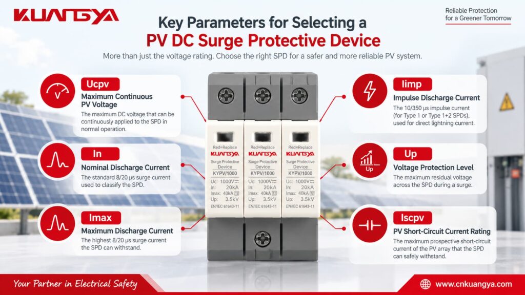
Ucpv is one of the most important parameters on a PV SPD.
It indicates the maximum DC voltage that may be continuously applied to the SPD under the specified conditions.
The selected Ucpv must be suitable for the highest voltage that can actually appear from the PV array.
Do not simply use the inverter’s nominal voltage.
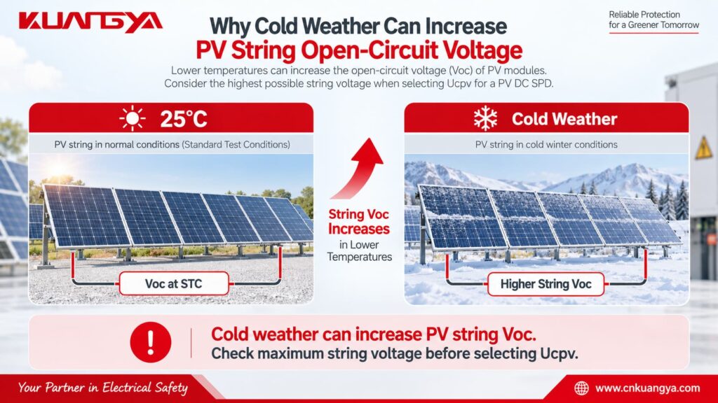
PV module open-circuit voltage increases when temperature decreases, so the maximum string voltage can be higher on a cold day than the value calculated from nominal operating voltage.
A simplified engineering calculation is:
Voc,max = Ns × Voc,STC × [1 + |βVoc| × (25°C − Tmin)]
Où ?
Voc,max = estimated maximum string open-circuit voltage
Ns = number of modules connected in series
Voc,STC = module open-circuit voltage at STC
βVoc = module Voc temperature coefficient expressed per °C
Tmin = minimum design temperature at the installation site
This simplified formula assumes the manufacturer’s temperature coefficient is applicable over the temperature range being considered.
For an actual project, always follow the PV module manufacturer’s calculation method and applicable electrical design requirements.
The important selection relationship is:
Ucpv ≥ maximum PV voltage that can continuously appear at the SPD
A safety margin or additional design factor may also be required by the applicable standard, manufacturer, or project specification.
In is the nominal discharge current that the SPD can withstand repeatedly under the specified test waveform.
For Type 2 SPDs, the commonly used test waveform is 8/20 μs.
A higher In generally indicates greater repetitive surge-current capability, but In should never be considered alone.
Imax is the maximum value of the 8/20 μs surge current that a Type 2 SPD can discharge under its specified test conditions.
It describes a maximum capability rather than normal repetitive operation.
Iimp is particularly important for Type 1 SPDs.
It is associated with the 10/350 μs lightning-current waveform and is used when the SPD may need to handle partial lightning current.
Up indicates the voltage protection level provided by the SPD during surge discharge.
A lower Up can provide better voltage limitation, but it still needs to be coordinated with the protected equipment and the rest of the surge protection system.
The SPD should limit the surge to a level compatible with the impulse withstand capability of the equipment being protected.
Iscpv is especially important for photovoltaic SPDs.
It represents the maximum prospective PV DC short-circuit current for which the SPD’s end-of-life and disconnection behavior has been evaluated.
The SPD must be suitable for the prospective short-circuit current available at the installation point.
This is another reason why choosing a PV SPD only by voltage is not enough.
Quick Check: Use the simple tool below to see whether the basic SPD application type and voltage marking appear compatible with your system.
Select the system type and the marking shown on the SPD. This quick check only evaluates basic AC/DC application compatibility and does not replace a full technical selection.
For PV systems, enter the maximum expected DC operating voltage rather than only the nominal inverter voltage.
Avis de non-responsabilité : This tool is for preliminary selection only. Always verify the SPD datasheet, system configuration, maximum operating voltage, short-circuit conditions, and applicable standards before installation.
This is one of the most common misunderstandings.
Suppose two SPDs are placed next to each other.
One says:
Uc: 1000V AC
The other says:
Ucpv : 1000V DC
Both contain the number “1000V,” but that does not make them interchangeable.
Their application ratings, test conditions, internal arrangement, insulation design, disconnection behavior, and applicable standards may be different.
Always read the complete marking.
Never remove “AC,” “DC,” or “PV” from the voltage specification when comparing products.
The differences are easier to understand when they are compared directly.
| Fonctionnalité | AC SPD | PV DC SPD |
|---|---|---|
| Main application | AC power distribution | DC side of PV systems |
| Supply | AC | DC |
| Natural zero crossing | Oui | Non |
| Typical voltage marking | Uc AC | Ucpv / Uc DC |
| DC fault interruption | Not assumed unless specified | Designed/tested for stated DC application |
| Common installation | Main distribution board, sub-panel | Combiner box, PV DC distribution, inverter DC side |
| Relevant IEC product standard | IEC 61643-11 | IEC 61643-31 |
| La tension maximale du système | According to AC rating | According to specified PV DC rating |
| PV short-circuit consideration | Not a PV rating | Iscpv may be specified |
| Typical protection types | Type 1, Type 1+2, Type 2 | PV Type 1, Type 1+2, Type 2 |
The most important difference is not the appearance of the product.
It is what electrical system the SPD has actually been designed, rated, and tested for.
The same principle works in reverse.
Do not assume a DC SPD can be installed on AC simply because its DC voltage rating is higher than the AC system voltage.
Par exemple :
A 1000V DC PV SPD is not automatically suitable for a 230V or 400V AC distribution board.
The manufacturer must provide an appropriate AC rating for that application.
If the device has both AC and DC ratings, follow the relevant rating for the system being protected.
If it is marked only as a PV DC SPD, use it only for the application specified by the manufacturer.
Not unless the manufacturer specifically provides a DC rating that covers that DC circuit.
A label such as:
Uc = 275V AC
does not mean:
275V DC
and certainly does not mean the device can be used on a 600V, 1000V, or 1500V PV system.
This is particularly important because 275V AC Type 2 SPDs are very common in low-voltage AC distribution systems.
Their familiar appearance can lead to incorrect use in DC equipment.
Always check the complete specification.
A better selection process starts with the electrical system, not with the SPD catalogue.
First determine where the SPD will be installed.
Par exemple :
PV modules → DC combiner box → DC cables → inverter DC input → inverter AC output
The SPD installed before the inverter on the PV side is protecting a DC circuit.
The SPD installed on the inverter's AC output is protecting an AC circuit.
These two locations normally require different SPD specifications.
If your inverter already includes surge protection, see our guide on whether a solar inverter with a built-in SPD still needs an external SPD.
Check the number of modules in series, module Voc, temperature coefficient, and minimum expected module temperature.
Do not rely only on the inverter's nominal operating voltage.
Cold weather can increase the open-circuit voltage of a PV string.
The selected Ucpv must be suitable for the highest expected PV voltage.
The appropriate SPD type depends on the lightning protection concept and installation.
A Type 2 PV SPD is widely used for protection against induced and switching surges.
A Type 1 or Type 1+2 SPD may be required where partial lightning current has to be handled, depending on the installation and lightning protection design.
Do not choose Type 1, Type 1+2, or Type 2 based only on the kA number printed on the front.
After confirming the voltage and SPD type, compare the discharge-current parameters and voltage protection level.
For a Type 2 SPD, In and Imax are especially relevant.
For a Type 1 or Type 1+2 SPD, Iimp is also important.
Up should be coordinated with the impulse withstand level of the equipment being protected.
The prospective short-circuit current at the installation point also matters.
Check whether the SPD's Iscpv is suitable for the PV source.
Also confirm the system configuration and the required protection modes between positive, negative, and PE.
For dedicated photovoltaic DC SPDs, look for documentation relevant to PV DC applications, such as IEC 61643-31 compliance where applicable.
Do not rely solely on the product's external appearance.
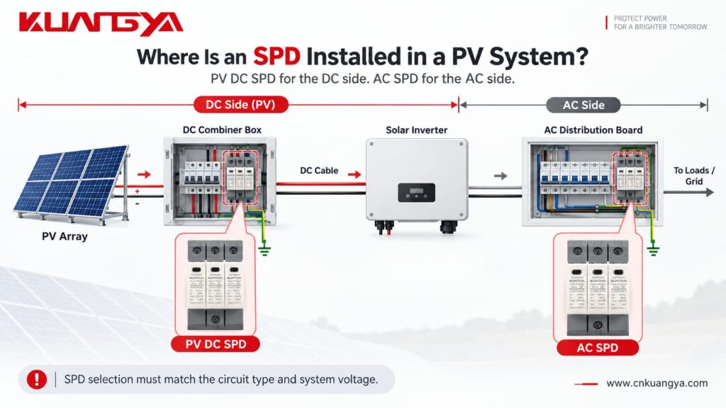
Common locations include the DC combiner box and the DC input side of the inverter.
In a larger PV system, protection may be required at more than one location depending on cable length, lightning protection design, equipment withstand level, and installation conditions.
The distance between the SPD and the protected inverter also matters.
Long connection conductors add inductive voltage during a surge, which can increase the effective voltage seen by the protected equipment.
Therefore, the SPD should not only be correctly selected — it should also be installed with short, direct connection conductors wherever possible.
If you want to understand this part in more detail, see:
La distance entre le parafoudre (SPD) et l'onduleur a-t-elle une importance ?
Non.
This is another common misunderstanding.
An incorrectly selected AC SPD installed on a DC system may not fail immediately.
Under normal conditions, the SPD is usually in a high-impedance standby state.
That means the installation can appear to operate normally even though the SPD is not correctly rated for the application.
The real problem may appear only when:
a strong surge occurs, the MOV ages, leakage current increases, the SPD experiences a temporary overvoltage, the device reaches end of life, or the thermal disconnector needs to operate.
Par conséquent :
“It has not failed yet” is not proof that an SPD is correctly selected.
Check its ratings instead.
A common mistake is using an AC SPD on a DC system simply because the voltage number printed on the device appears to match. Other common mistakes include ignoring the AC/DC marking, assuming a higher voltage rating automatically makes an SPD safer, ignoring the maximum PV open-circuit voltage in cold conditions, overlooking Iscpv, choosing an SPD only by Imax, and assuming a green status window proves that the SPD is correct for the application.
A green indicator normally tells you something about the current mechanical or electrical status of the protection module.
It does pas prove that the model was correctly selected for the system.
Before installing an SPD, answer these questions:
| Vérifier | Question |
|---|---|
| Système | Is the circuit AC or DC? |
| Application | Is it specifically a PV circuit? |
| Tension | What is the maximum continuous system voltage? |
| SPD rating | Is Uc or Ucpv suitable for that voltage? |
| Le type de parafoudre (SPD) | Type 1, Type 1+2, or Type 2? |
| Surge current | Are In, Imax and/or Iimp appropriate? |
| Protection level | Is Up coordinated with the equipment? |
| Short-circuit capability | Is Iscpv suitable for the PV source? |
| Configuration | Does the connection arrangement match the PV system? |
| Standard | Is the SPD designed and tested for the intended application? |
If any of these points are unclear, check the manufacturer's datasheet before energizing the circuit.
Only if the manufacturer specifically provides a DC rating for the device and that rating is suitable for the DC system. An SPD marked only for AC operation should not automatically be used on a DC circuit.
Not necessarily. It may initially appear to operate normally. However, an incorrectly rated SPD can overheat or fail to disconnect safely under abnormal conditions. Severe failure may result in arcing, burning, fire, or enclosure rupture.
No. A 275V AC rating does not make the device suitable for a 600V DC PV system. Use an SPD specifically rated for the required DC voltage and PV application.
Do not assume that you can. The identical voltage number does not mean the application ratings are equivalent. Check whether the manufacturer explicitly provides an appropriate 1000V DC rating.
Uc generally refers to maximum continuous operating voltage. For photovoltaic applications, Ucpv specifically identifies the maximum continuous DC voltage applicable to the PV SPD. The selected value must be suitable for the highest PV voltage that can occur at the installation.
The SPD may be subjected to excessive continuous electrical stress. This can increase leakage current, accelerate degradation, cause overheating, and eventually trigger or damage the disconnection mechanism.
Non.
Ucpv must be high enough for the PV system, but SPD selection is a balance between continuous operating voltage and protection performance.
You should also consider Up, discharge-current ratings, equipment withstand voltage, system configuration, and manufacturer recommendations.
Check the product label and datasheet.
Look for clear markings such as:
275V AC
Uc 440V AC
Ucpv 1000V DC
Ucpv 1500V DC
Also check the applicable product standard and wiring configuration.
Never identify an AC or DC SPD only by its shape or number of poles.
An AC SPD and a DC SPD may look almost identical, but that does not mean they can be used interchangeably.
The biggest mistake is choosing an SPD only by the voltage number printed on the front.
A 1000V rating does not tell the whole story.
You also need to know whether the rating applies to AC or DC, whether the SPD is suitable for photovoltaic use, its maximum continuous operating voltage, discharge-current capability, voltage protection level, short-circuit capability, system configuration, and applicable standard.
Using an AC SPD on a DC system does not mean it will immediately explode, but the device must have a suitable DC rating for the application.
However, an SPD that is not designed for the DC application may experience excessive stress and may not disconnect safely at the end of its life. This can lead to overheating, sustained arcing, burning, fire, and in severe cases enclosure rupture.
For a photovoltaic DC system, use a surge protective device specifically designed and rated for the PV DC application.
KUANGYA provides DC surge protection solutions for different photovoltaic system voltages, including 600V DC, 1000V DC, and 1500V DC applications, with different SPD configurations available for solar PV protection.

