Промышленная зона Вэньян Юэцин Вэньчжоу 325000
Рабочие часы
Понедельник - пятница: 7AM - 7PM
Выходные: 10AM - 5PM
Промышленная зона Вэньян Юэцин Вэньчжоу 325000
Рабочие часы
Понедельник - пятница: 7AM - 7PM
Выходные: 10AM - 5PM

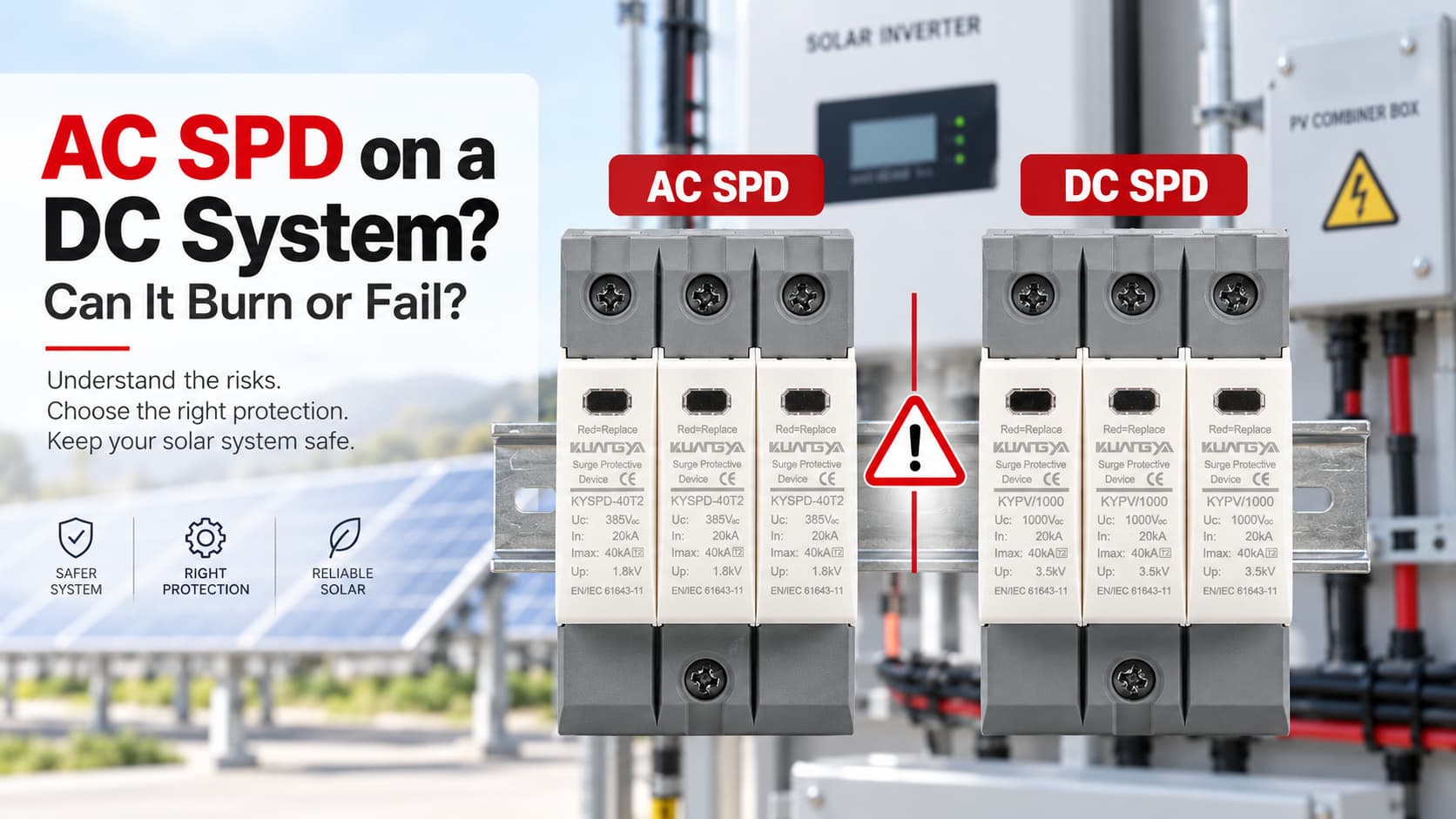
Использование УЗИП переменного тока в системе постоянного тока может быть опасным, если устройство не рассчитано специально для применения в цепях постоянного тока.
УЗИП переменного и постоянного тока могут выглядеть очень похоже внешне, но они не являются автоматически взаимозаменяемыми. Одной из самых распространенных ошибок является сравнение только напряжения, указанного на этикетке. Например, кто-то может увидеть “1000 В” на УЗИП и предположить, что его можно установить в солнечной фотоэлектрической системе постоянного тока на 1000 В.
Такое предположение может быть опасным.
УЗИП следует устанавливать в системе постоянного тока только в том случае, если производитель специально сертифицировал его для данного применения, а его электрические характеристики соответствуют параметрам системы.
Использование УЗИП, предназначенного только для цепей переменного тока (AC), в цепях постоянного тока (DC) может привести к перегреву, выходу из строя внутреннего механизма отключения, возникновению устойчивой электрической дуги, возгоранию или пожару. В случае серьезной неисправности корпус УЗИП может разрушиться.
Итак, может ли УЗИП для переменного тока взорваться при подключении к цепи постоянного тока?
Не обязательно. Однако использование неподходящего УЗИП создает серьезный риск отказа, а тяжелый тепловой или электрический сбой может привести к разрушению корпуса.
УЗИП для переменного тока не следует использовать в системах постоянного тока только потому, что значения напряжения кажутся схожими.
Устройство, предназначенное только для работы в цепях переменного тока, было спроектировано и испытано для условий систем переменного тока. УЗИП для фотоэлектрических систем постоянного тока разработано с учетом постоянного напряжения, условий возникновения неисправностей, конфигурации системы и требований к отключению, характерных для стороны постоянного тока фотоэлектрической установки.
Для фотоэлектрических систем всегда проверяйте полные характеристики УЗИП, особенно: Ucpv, In, Imax, Iimp (где применимо), Up, Iscpv, тип УЗИП, конфигурацию подключения и применимый стандарт..
Как правило, не следует использовать УЗИП, предназначенное только для сетей переменного тока, в сетях постоянного тока.
Ключевое слово — “номинальный”.”
Если производитель четко указывает, что конкретное УЗИП подходит как для сетей переменного, так и постоянного тока, его можно использовать в пределах заявленных номинальных характеристик и условий установки.
Однако УЗИП, имеющее маркировку только для сетей переменного тока, не должно автоматически устанавливаться в цепях постоянного тока.
Например:
| Маркировка УЗИП | Система | Подходит? |
|---|---|---|
| Uc 275В AC | Фотоэлектрическая система 600 В пост. тока | Нет |
| Uc 440 В перем. тока | Фотоэлектрическая система 1000 В пост. тока | Нет |
| Ucpv 1000 В пост. тока | Подходящая фотоэлектрическая система в пределах номинальных параметров | Возможно, да |
| УЗИП с двойным номиналом для сетей перем./пост. тока | Соответствующая система перем. или пост. тока | Проверьте технические характеристики производителя. |
Именно поэтому недостаточно ориентироваться только на значение напряжения.
1000 В переменного тока и 1000 В постоянного тока — это не одно и то же номинальное применение.
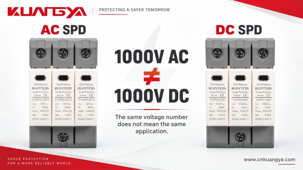
Буквы после цифр имеют значение.
И УЗИП для переменного, и УЗИП для постоянного тока выполняют одну и ту же основную задачу: они помогают ограничить переходное перенапряжение и отвести импульсный ток от чувствительного оборудования.
Однако электрические среды, в которых они работают, различаются.
Эта разница становится особенно важной в нештатных режимах работы и по истечении срока службы УЗИП.
В нормальной синусоидальной системе переменного тока мгновенные значения напряжения и тока периодически проходят через ноль.
При частоте 50 Гц или 60 Гц это происходит многократно каждую секунду.
Естественные переходы через ноль способствуют гашению дуги при размыкании коммутационного или защитного устройства.
Это одна из причин, почему оборудование, предназначенное для коммутации переменного тока и отключения токов короткого замыкания, нельзя автоматически считать безопасным для работы в цепях постоянного тока.
Источник постоянного тока поддерживает неизменную полярность и не проходит через ноль естественным образом, как это происходит в цепях переменного тока.
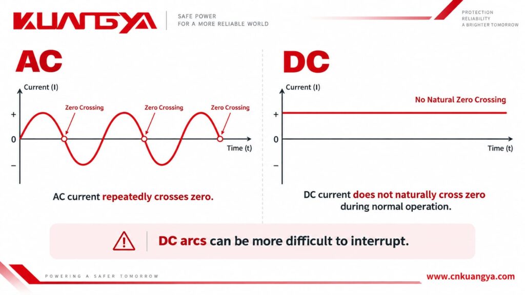
В связи с этим, если возникает дуга постоянного тока, ее гашение может быть более затруднительным.
Это важно в фотоэлектрических системах, поскольку солнечная батарея может продолжать подачу питания постоянного тока при наличии солнечного света.
Если устройство защиты от перенапряжения (УЗИП) перегружается и его внутренняя система отключения должна изолировать неисправный защитный компонент, устройство должно быть спроектировано так, чтобы безопасно работать в условиях постоянного тока.
Это одна из причин, по которой специализированные УЗИП для фотоэлектрических систем постоянного тока используют конструкции и схемы отключения, предназначенные для применения в цепях постоянного тока.
Компания Phoenix Contact также поясняет, что системы постоянного тока ведут себя иначе, чем системы переменного тока, и поэтому требуют устройств защиты от перенапряжения, разработанных для применения в цепях постоянного тока..
Установка УЗИП для переменного тока в систему постоянного тока может не привести к немедленному видимому отказу, и единого сценария выхода из строя не существует.
Результат зависит от конструкции УЗИП, напряжения постоянного тока, доступного тока, конфигурации системы, температуры, истории перенапряжений и характера выхода УЗИП из строя.
Неправильно выбранное устройство защиты от импульсных перенапряжений (УЗИП) поначалу может выглядеть исправным.
Именно это делает данную ошибку опасной.
| Возможные условия | Возможные последствия |
|---|---|
| Сразу после установки | УЗИП может выглядеть полностью исправным |
| Длительное воздействие перенапряжения | Варистор (MOV) или другие защитные компоненты могут нагреваться |
| Деградация компонентов | Ток утечки может увеличиться |
| Тепловая перегрузка | Может сработать внутренний терморасцепитель |
| Ненадлежащее прерывание постоянного тока | Дуга может продолжать гореть после начала размыкания контактов |
| Серьезный отказ | Возможно возникновение горения, дыма или пожара |
| Критический отказ | Корпус может треснуть или разрушиться |
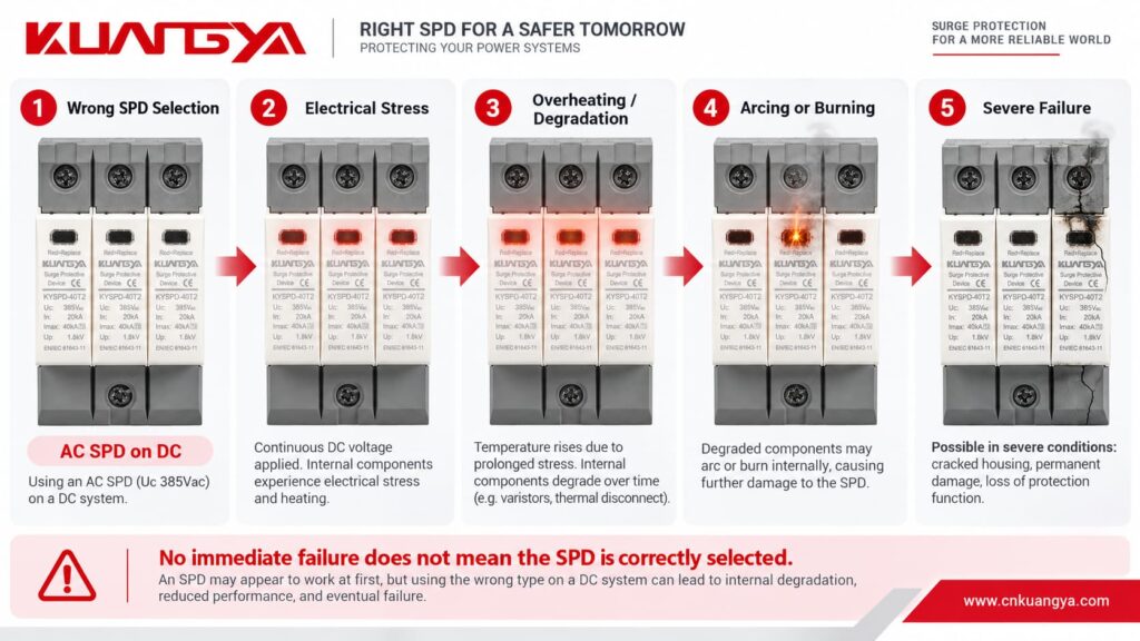
Ключевой момент заключается в следующем:
Отсутствие немедленного отказа не означает, что УЗИП выбрано правильно.
Неправильно установленное УЗИП может проработать недели или месяцы, прежде чем скачок напряжения, изменение температуры, состояние сети, проблемы с изоляцией или деградация компонентов приведут к выходу из строя.
Смотрите: что произойдет, если использовать неподходящее УЗИП в системе постоянного тока?
Этот вопрос требует тщательного ответа.
Подключение устройства защиты от импульсных перенапряжений (УЗИП) переменного тока к цепи постоянного тока не означает, что оно мгновенно взорвется.
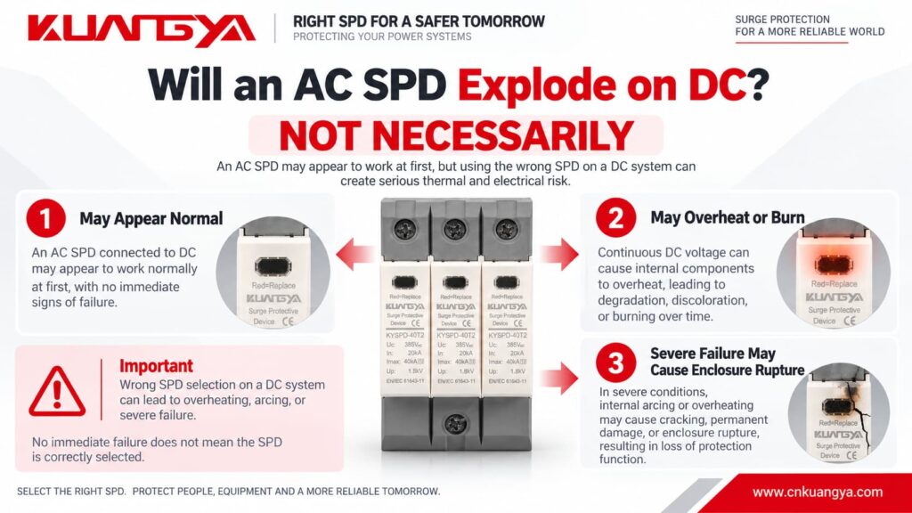
Во многих случаях при неправильной установке ничего критического не происходит сразу.
Основная проблема заключается в том, что произойдет, когда УЗИП подвергнется электрической или тепловой нагрузке.
Упрощенная последовательность отказа может выглядеть следующим образом:
Неправильный выбор УЗИП → чрезмерная электрическая нагрузка → нагрев или деградация → увеличение тока утечки или тока повреждения → сложность отключения → возникновение дуги или возгорание → возможный разрыв корпуса
Поэтому, утверждение:
“Устройство защиты от импульсных перенапряжений (УЗИП) переменного тока взорвется при подключении к цепи постоянного тока”
является слишком категоричным утверждением.
Более технически точное утверждение:
Использование УЗИП, не рассчитанного на применение в цепях постоянного тока, может создать серьезный риск перегрева и возгорания. В условиях тяжелых аварийных режимов УЗИП может сгореть или его корпус может разрушиться.
“Термин ”взрыв» часто используется в разговорной речи для описания поврежденного или разрушенного УЗИП, однако сильное разрушение корпуса является более точным техническим описанием.
Если УЗИП уже установлено и у вас есть опасения, что оно могло быть повреждено, ознакомьтесь с нашим руководством о том, как определить неисправность УЗИП.
Во многих УЗИП используются металлооксидные варисторы, обычно называемые MOV.
During normal operation, a correctly selected MOV-based SPD has very low leakage current.
During a transient overvoltage, the MOV becomes conductive and diverts surge current.
After the surge disappears, it should return to its high-resistance state.
However, repeated surge events, temporary overvoltage, excessive continuous voltage, aging, or incorrect application can gradually degrade the MOV.
As degradation progresses, leakage current may increase.
More leakage current creates more heat.
More heat may cause additional degradation.
This process can eventually result in thermal runaway if the device is not safely disconnected.
Modern SPDs therefore commonly include a thermal disconnection mechanism designed to isolate an overloaded MOV.
In a DC application, that disconnection mechanism must also be capable of safely dealing with the DC conditions that appear when the device disconnects.
Imagine two contacts beginning to separate while current is flowing.
As the gap becomes larger, an electrical arc can form between them.
In AC, the current naturally passes through zero periodically. This can assist arc extinction.
In DC, there is no equivalent natural current zero during normal operation.
The arc can therefore continue unless the device has been designed with an appropriate method to interrupt it.
This principle is not limited to SPDs.
It is also one reason why DC circuit breakers, DC isolators, contactors, and fuses need appropriate DC ratings.
The same general rule applies:
Never assume an AC electrical device is suitable for DC only because the voltage appears similar.
If you also want to understand how a typical power SPD is connected in the circuit, see our guide on why an SPD is connected in parallel instead of series.
Нет.
Voltage is only one part of SPD selection.
For a photovoltaic DC SPD, several parameters need to be considered together.
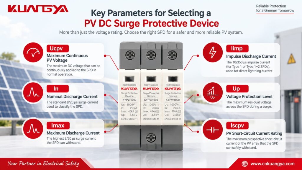
Ucpv is one of the most important parameters on a PV SPD.
It indicates the maximum DC voltage that may be continuously applied to the SPD under the specified conditions.
The selected Ucpv must be suitable for the highest voltage that can actually appear from the PV array.
Do not simply use the inverter’s nominal voltage.
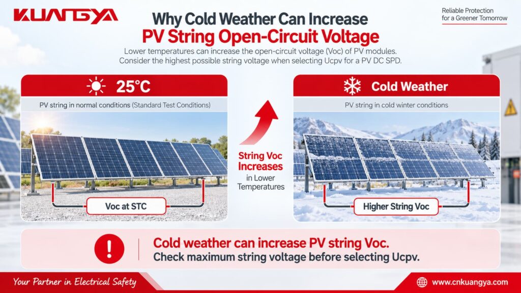
PV module open-circuit voltage increases when temperature decreases, so the maximum string voltage can be higher on a cold day than the value calculated from nominal operating voltage.
A simplified engineering calculation is:
Voc,max = Ns × Voc,STC × [1 + |βVoc| × (25°C − Tmin)]
Где:
Voc,max = estimated maximum string open-circuit voltage
Ns = number of modules connected in series
Voc,STC = module open-circuit voltage at STC
βVoc = module Voc temperature coefficient expressed per °C
Tmin = minimum design temperature at the installation site
This simplified formula assumes the manufacturer’s temperature coefficient is applicable over the temperature range being considered.
For an actual project, always follow the PV module manufacturer’s calculation method and applicable electrical design requirements.
The important selection relationship is:
Ucpv ≥ maximum PV voltage that can continuously appear at the SPD
A safety margin or additional design factor may also be required by the applicable standard, manufacturer, or project specification.
In is the nominal discharge current that the SPD can withstand repeatedly under the specified test waveform.
For Type 2 SPDs, the commonly used test waveform is 8/20 μs.
A higher In generally indicates greater repetitive surge-current capability, but In should never be considered alone.
Imax is the maximum value of the 8/20 μs surge current that a Type 2 SPD can discharge under its specified test conditions.
It describes a maximum capability rather than normal repetitive operation.
Iimp is particularly important for Type 1 SPDs.
It is associated with the 10/350 μs lightning-current waveform and is used when the SPD may need to handle partial lightning current.
Up indicates the voltage protection level provided by the SPD during surge discharge.
A lower Up can provide better voltage limitation, but it still needs to be coordinated with the protected equipment and the rest of the surge protection system.
The SPD should limit the surge to a level compatible with the impulse withstand capability of the equipment being protected.
Iscpv is especially important for photovoltaic SPDs.
It represents the maximum prospective PV DC short-circuit current for which the SPD’s end-of-life and disconnection behavior has been evaluated.
The SPD must be suitable for the prospective short-circuit current available at the installation point.
This is another reason why choosing a PV SPD only by voltage is not enough.
Quick Check: Use the simple tool below to see whether the basic SPD application type and voltage marking appear compatible with your system.
Select the system type and the marking shown on the SPD. This quick check only evaluates basic AC/DC application compatibility and does not replace a full technical selection.
For PV systems, enter the maximum expected DC operating voltage rather than only the nominal inverter voltage.
Отказ от ответственности: This tool is for preliminary selection only. Always verify the SPD datasheet, system configuration, maximum operating voltage, short-circuit conditions, and applicable standards before installation.
This is one of the most common misunderstandings.
Suppose two SPDs are placed next to each other.
One says:
Uc: 1000V AC
The other says:
Ucpv: 1000 В пост. тока
Both contain the number “1000V,” but that does not make them interchangeable.
Their application ratings, test conditions, internal arrangement, insulation design, disconnection behavior, and applicable standards may be different.
Always read the complete marking.
Never remove “AC,” “DC,” or “PV” from the voltage specification when comparing products.
The differences are easier to understand when they are compared directly.
| Характеристика | AC SPD | PV DC SPD |
|---|---|---|
| Main application | AC power distribution | DC side of PV systems |
| Supply | AC | DC |
| Natural zero crossing | Да | Нет |
| Typical voltage marking | Uc AC | Ucpv / Uc DC |
| DC fault interruption | Not assumed unless specified | Designed/tested for stated DC application |
| Common installation | Main distribution board, sub-panel | Combiner box, PV DC distribution, inverter DC side |
| Relevant IEC product standard | IEC 61643-11 | IEC 61643-31 |
| Максимальное напряжение системы | According to AC rating | According to specified PV DC rating |
| PV short-circuit consideration | Not a PV rating | Iscpv may be specified |
| Typical protection types | Type 1, Type 1+2, Type 2 | PV Type 1, Type 1+2, Type 2 |
The most important difference is not the appearance of the product.
It is what electrical system the SPD has actually been designed, rated, and tested for.
The same principle works in reverse.
Do not assume a DC SPD can be installed on AC simply because its DC voltage rating is higher than the AC system voltage.
Например:
A 1000V DC PV SPD is not automatically suitable for a 230V or 400V AC distribution board.
The manufacturer must provide an appropriate AC rating for that application.
If the device has both AC and DC ratings, follow the relevant rating for the system being protected.
If it is marked only as a PV DC SPD, use it only for the application specified by the manufacturer.
Not unless the manufacturer specifically provides a DC rating that covers that DC circuit.
A label such as:
Uc = 275V AC
does not mean:
275V DC
and certainly does not mean the device can be used on a 600V, 1000V, or 1500V PV system.
This is particularly important because 275V AC Type 2 SPDs are very common in low-voltage AC distribution systems.
Their familiar appearance can lead to incorrect use in DC equipment.
Always check the complete specification.
A better selection process starts with the electrical system, not with the SPD catalogue.
First determine where the SPD will be installed.
Например:
PV modules → DC combiner box → DC cables → inverter DC input → inverter AC output
The SPD installed before the inverter on the PV side is protecting a DC circuit.
The SPD installed on the inverter's AC output is protecting an AC circuit.
These two locations normally require different SPD specifications.
If your inverter already includes surge protection, see our guide on whether a solar inverter with a built-in SPD still needs an external SPD.
Check the number of modules in series, module Voc, temperature coefficient, and minimum expected module temperature.
Do not rely only on the inverter's nominal operating voltage.
Cold weather can increase the open-circuit voltage of a PV string.
The selected Ucpv must be suitable for the highest expected PV voltage.
The appropriate SPD type depends on the lightning protection concept and installation.
A Type 2 PV SPD is widely used for protection against induced and switching surges.
A Type 1 or Type 1+2 SPD may be required where partial lightning current has to be handled, depending on the installation and lightning protection design.
Do not choose Type 1, Type 1+2, or Type 2 based only on the kA number printed on the front.
After confirming the voltage and SPD type, compare the discharge-current parameters and voltage protection level.
For a Type 2 SPD, In and Imax are especially relevant.
For a Type 1 or Type 1+2 SPD, Iimp is also important.
Up should be coordinated with the impulse withstand level of the equipment being protected.
The prospective short-circuit current at the installation point also matters.
Check whether the SPD's Iscpv is suitable for the PV source.
Also confirm the system configuration and the required protection modes between positive, negative, and PE.
For dedicated photovoltaic DC SPDs, look for documentation relevant to PV DC applications, such as IEC 61643-31 compliance where applicable.
Do not rely solely on the product's external appearance.
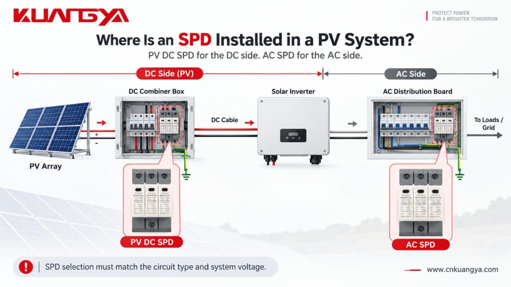
Common locations include the DC combiner box and the DC input side of the inverter.
In a larger PV system, protection may be required at more than one location depending on cable length, lightning protection design, equipment withstand level, and installation conditions.
The distance between the SPD and the protected inverter also matters.
Long connection conductors add inductive voltage during a surge, which can increase the effective voltage seen by the protected equipment.
Therefore, the SPD should not only be correctly selected — it should also be installed with short, direct connection conductors wherever possible.
If you want to understand this part in more detail, see:
Имеет ли значение расстояние между УЗИП и инвертором?
Нет.
This is another common misunderstanding.
An incorrectly selected AC SPD installed on a DC system may not fail immediately.
Under normal conditions, the SPD is usually in a high-impedance standby state.
That means the installation can appear to operate normally even though the SPD is not correctly rated for the application.
The real problem may appear only when:
a strong surge occurs, the MOV ages, leakage current increases, the SPD experiences a temporary overvoltage, the device reaches end of life, or the thermal disconnector needs to operate.
Поэтому:
“It has not failed yet” is not proof that an SPD is correctly selected.
Check its ratings instead.
A common mistake is using an AC SPD on a DC system simply because the voltage number printed on the device appears to match. Other common mistakes include ignoring the AC/DC marking, assuming a higher voltage rating automatically makes an SPD safer, ignoring the maximum PV open-circuit voltage in cold conditions, overlooking Iscpv, choosing an SPD only by Imax, and assuming a green status window proves that the SPD is correct for the application.
A green indicator normally tells you something about the current mechanical or electrical status of the protection module.
It does не prove that the model was correctly selected for the system.
Before installing an SPD, answer these questions:
| Проверьте | Вопрос |
|---|---|
| Система | Is the circuit AC or DC? |
| Приложение | Is it specifically a PV circuit? |
| Напряжение | What is the maximum continuous system voltage? |
| SPD rating | Is Uc or Ucpv suitable for that voltage? |
| Тип УЗИП | Type 1, Type 1+2, or Type 2? |
| Surge current | Are In, Imax and/or Iimp appropriate? |
| Protection level | Is Up coordinated with the equipment? |
| Short-circuit capability | Is Iscpv suitable for the PV source? |
| Конфигурация | Does the connection arrangement match the PV system? |
| Стандарт | Is the SPD designed and tested for the intended application? |
If any of these points are unclear, check the manufacturer's datasheet before energizing the circuit.
Only if the manufacturer specifically provides a DC rating for the device and that rating is suitable for the DC system. An SPD marked only for AC operation should not automatically be used on a DC circuit.
Not necessarily. It may initially appear to operate normally. However, an incorrectly rated SPD can overheat or fail to disconnect safely under abnormal conditions. Severe failure may result in arcing, burning, fire, or enclosure rupture.
No. A 275V AC rating does not make the device suitable for a 600V DC PV system. Use an SPD specifically rated for the required DC voltage and PV application.
Do not assume that you can. The identical voltage number does not mean the application ratings are equivalent. Check whether the manufacturer explicitly provides an appropriate 1000V DC rating.
Uc generally refers to maximum continuous operating voltage. For photovoltaic applications, Ucpv specifically identifies the maximum continuous DC voltage applicable to the PV SPD. The selected value must be suitable for the highest PV voltage that can occur at the installation.
The SPD may be subjected to excessive continuous electrical stress. This can increase leakage current, accelerate degradation, cause overheating, and eventually trigger or damage the disconnection mechanism.
Нет.
Ucpv must be high enough for the PV system, but SPD selection is a balance between continuous operating voltage and protection performance.
You should also consider Up, discharge-current ratings, equipment withstand voltage, system configuration, and manufacturer recommendations.
Check the product label and datasheet.
Look for clear markings such as:
275V AC
Uc 440 В перем. тока
Ucpv 1000 В пост. тока
Ucpv 1500V DC
Also check the applicable product standard and wiring configuration.
Never identify an AC or DC SPD only by its shape or number of poles.
An AC SPD and a DC SPD may look almost identical, but that does not mean they can be used interchangeably.
The biggest mistake is choosing an SPD only by the voltage number printed on the front.
A 1000V rating does not tell the whole story.
You also need to know whether the rating applies to AC or DC, whether the SPD is suitable for photovoltaic use, its maximum continuous operating voltage, discharge-current capability, voltage protection level, short-circuit capability, system configuration, and applicable standard.
Using an AC SPD on a DC system does not mean it will immediately explode, but the device must have a suitable DC rating for the application.
However, an SPD that is not designed for the DC application may experience excessive stress and may not disconnect safely at the end of its life. This can lead to overheating, sustained arcing, burning, fire, and in severe cases enclosure rupture.
For a photovoltaic DC system, use a surge protective device specifically designed and rated for the PV DC application.
KUANGYA provides DC surge protection solutions for different photovoltaic system voltages, including 600V DC, 1000V DC, and 1500V DC applications, with different SPD configurations available for solar PV protection.

