منطقة ونغ يانغ الصناعية يويتشينغ ونتشو 325000
ساعات العمل
من الاثنين إلى الجمعة: 7 صباحاً - 7 مساءً
عطلة نهاية الأسبوع 10 صباحاً - 5 مساءً
منطقة ونغ يانغ الصناعية يويتشينغ ونتشو 325000
ساعات العمل
من الاثنين إلى الجمعة: 7 صباحاً - 7 مساءً
عطلة نهاية الأسبوع 10 صباحاً - 5 مساءً

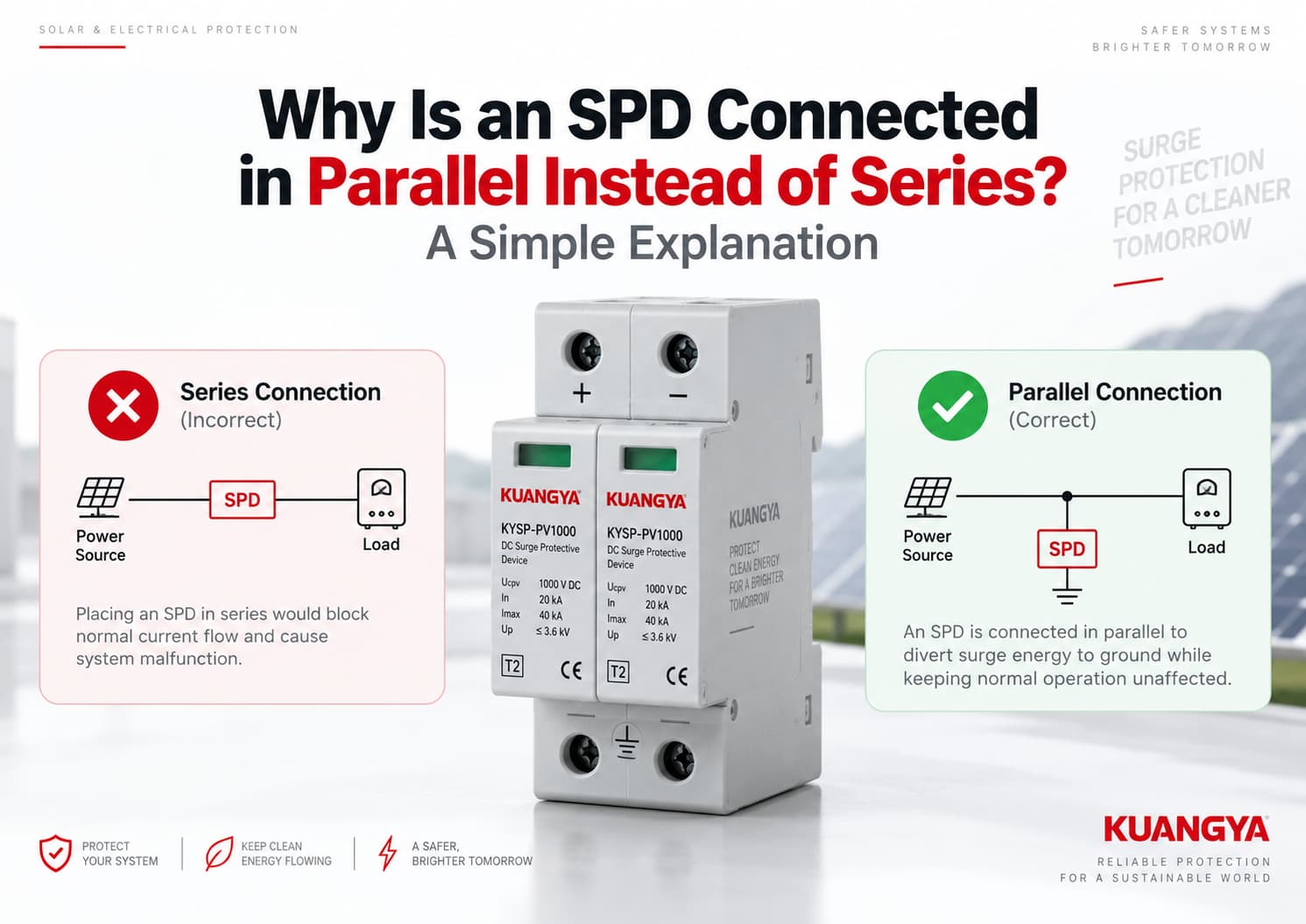
إذا نظرت إلى تركيب جهاز الحماية من اندفاع التيار (SPD) النموذجي، فقد تلاحظ شيئاً مختلفاً عن المصهر أو قاطع الدائرة.
يتم تركيب المصهر أو قاطع الدائرة عادةً على التوالي مع الدائرة، بحيث يمر تيار الحمل من خلاله.
عادة ما يكون جهاز الحماية من اندفاع التيار (SPD) النموذجي متصلاً على التوازي مع الدائرة التي يحميها، وهذا هو السبب في أن العديد من الفنيين يتساءلون لماذا يتم توصيل جهاز الحماية من اندفاع التيار (SPD) على التوازي بدلاً من التوالي..
لماذا؟
الإجابة البسيطة هي أن جهاز الحماية من زيادة التيار (SPD) الموصل على التوازي لا يحتاج إلى حمل تيار التشغيل العادي. في ظروف التشغيل العادية، يظل الجهاز في حالة مقاومة عالية. وعند حدوث زيادة مفاجئة في الجهد، يبدأ الجهاز في التوصيل ويوفر مساراً منخفض المقاومة لتيار الاندفاع، مما يحد من الجهد الواصل إلى المعدات المحمية.
ولهذا السبب يُستخدم التوصيل على التوازي على نطاق واسع لأجهزة الحماية من زيادة التيار (SPD) من النوع 1 والنوع 2 في أنظمة توزيع الطاقة والأنظمة الكهروضوئية.
ومع ذلك، فإن قاعدة “جهاز الحماية من زيادة التيار (SPD) = توصيل على التوازي دائماً” ليست قاعدة مطلقة. إذ توجد أيضاً أجهزة حماية من زيادة التيار ومرشحات اندفاع موصلة على التوالي لتطبيقات معينة. في هذا المقال، نتحدث بشكل أساسي عن أجهزة الحماية من زيادة التيار الموصلة على التوازي والمستخدمة في أنظمة توزيع التيار المتردد وأنظمة الطاقة الشمسية الكهروضوئية ذات التيار المستمر.
نموذجي جهاز حماية من زيادة التيار (SPD) موصل على التوازي مصمم للاستجابة لأحداث الجهد الزائد المؤقت دون حمل تيار التشغيل العادي للحمل.
في الظروف العادية:
مصدر الطاقة ← الحمل
يظل جهاز الحماية من زيادة التيار (SPD) في وضع الاستعداد.
عند حدوث ارتفاع مفاجئ في الجهد، يغير جهاز الحماية من زيادة التيار (SPD) سلوكه الكهربائي ويقوم بتمرير تيار الارتفاع عبر مسار الحماية الخاص به، مما يساعد في الحد من الجهد الذي يظهر عبر المعدات الحساسة.
يبدو الترتيب المتوازي المبسط كما يلي:
مصدر الطاقة ───────────── الحمل
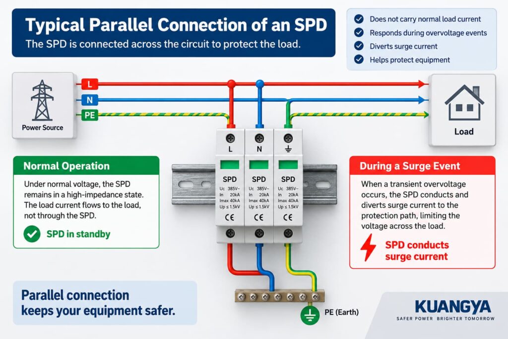
يتم توصيل جهاز الحماية من زيادة التيار (SPD) عبر الدائرة بدلاً من إدراجه مباشرة في مسار تيار الحمل العادي. أساسيات الحماية من زيادة التيار من شركة فينيكس كونتاكت (Phoenix Contact) توضح أيضاً أنه يمكن تركيب أجهزة الحماية من زيادة التيار (SPDs) على التوازي مع المعدات المحمية أو بين الموصلات ذات الصلة.
تصف شركة إيتون (Eaton) أجهزة الحماية من زيادة التيار (SPDs) المتصلة على التوازي، أو المتصلة كتحويلة، بنفس الطريقة: موصلاتها لا تحمل تيار الإمداد العادي، بل تحمل تياراً قصير المدة مرتبطاً بالأحداث العابرة.
يفسر هذا الاختلاف الأساسي سبب تركيب معظم أجهزة الحماية من زيادة التيار (SPDs) الشائعة على التوازي.
لفهم التوصيل على التوازي، من المفيد أولاً فهم ما يفعله جهاز الحماية من زيادة التيار (SPD) في حالة عدم وجود زيادة في الجهد.
أثناء التشغيل العادي، يظل جهد النظام أقل من المستوى الذي يبدأ عنده جهاز الحماية من زيادة التيار (SPD) في التوصيل بشكل ملحوظ.
بالنسبة لجهاز الحماية من زيادة التيار (SPD) القائم على مقاومة أكسيد المعدن (MOV)، يمثل عنصر الحماية معاوقة عالية نسبياً في ظروف الجهد العادي.
هذا يعني أن تيار التشغيل الرئيسي يستمر عبر دائرة الطاقة العادية إلى الحمل.
يكون جهاز الحماية من زيادة التيار (SPD) في وضع الاستعداد بشكل أساسي.
وجهة نظر مبسطة هي:
المصدر ───────────────── الحمل
هذا لا يعني بالضرورة عدم مرور أي تيار على الإطلاق عبر كل جهاز حماية من التذبذبات (SPD). فاعتماداً على تقنية وتصميم الجهاز، قد يوجد تيار تسريب أو تيار تشغيل بسيط.
النقطة المهمة هي:
لا يحتاج تيار الحمل الطبيعي إلى المرور عبر جهاز الحماية من التذبذبات (SPD) الموصل على التوازي.
فكر في جهاز الحماية من التذبذبات (SPD) كمسار حماية ينتظر بجانب الدائرة الرئيسية بدلاً من كونه مكوناً يجب أن يحمل تيار تشغيل المعدات بشكل مستمر.
التذبذب هو زيادة قصيرة المدة في الجهد قد تنتج عن أحداث مثل العواصف الرعدية أو عمليات التبديل في الشبكة.
عندما يرتفع الجهد عبر جهاز الحماية من زيادة التيار (SPD) بشكل كافٍ، تبدأ عناصر الحماية في الجهاز بالتوصيل.
إذا كنت ترغب في شرح أعمق لكيفية استجابة عناصر الحماية للجهد الزائد العابر، راجع دليلنا حول كيفية عمل جهاز الحماية من التيار المستمر (DC SPD).
تنخفض معاوقته بشكل حاد مقارنة بالحالة الطبيعية.
يسمح هذا لتيار الاندفاع بالتدفق عبر مسار الحماية المتاح ويحد من الجهد العابر الذي يظهر عبر المعدات المحمية.
التمثيل المبسط هو:
المعدات
ومع ذلك، فإن هذا الرسم التخطيطي هو مجرد مثال مبسط.
يقوم جهاز الحماية من زيادة التيار (SPD) بـ لا تقوم دائماً بتحويل كل زيادة مفاجئة في التيار مباشرة إلى الأرض.
اعتماداً على النظام الكهربائي وتصميم جهاز الحماية من زيادة التيار (SPD)، قد توجد أنماط حماية بين:
لهذا السبب، من الأدق القول:
يوفر جهاز الحماية من زيادة التيار (SPD) مساراً محكماً لتيار الاندفاع ويحد من الجهد العابر عبر المعدات التي يحميها.
يعتمد مسار التيار الدقيق على تكوين جهاز الحماية من زيادة التيار (SPD) وطوبولوجيا النظام.
لفهم سبب توصيل جهاز الحماية من زيادة التيار (SPD) على التوازي، من المفيد النظر في ما يحدث أثناء التشغيل العادي وأثناء حدوث زيادة في التيار.
هناك عدة أسباب مهمة تجعل جهاز حماية من زيادة التيار (SPD) موصل على التوازي يُستخدم على نطاق واسع في أنظمة توزيع الطاقة.
هذا أحد أكبر الاختلافات بين جهاز الحماية من زيادة التيار (SPD) والأجهزة الأخرى مثل قاطع الدائرة أو المصهر.
تخيل أن العاكس يعمل عادةً عند عشرات الأمبيرات.
مع جهاز حماية من اندفاع التيار (SPD) موصل على التوازي، لا يضطر تيار التشغيل هذا إلى المرور باستمرار عبر جهاز الحماية.
بدلاً من ذلك:
المصدر ───────────────── الحمل
يتم توصيل جهاز الحماية من اندفاع التيار (SPD) عبر الدائرة المحمية.
هذا يعني أنه يمكن اختيار جهاز الحماية من اندفاع التيار (SPD) بشكل أساسي وفقاً لمتطلبات الحماية من الاندفاع بدلاً من اختياره وفقاً لتيار التشغيل الكامل لكل حمل في اتجاه التيار.
تشير شركة فينيكس كونتاكت (Phoenix Contact) بالمثل إلى أن أجهزة الحماية من اندفاع التيار (SPDs) الخاصة بها والمثبتة على التوازي تظهر كهربائياً كفرع متصل عبر نظام توزيع الطاقة بدلاً من تحمل سعة التيار العادية للدائرة.
جهاز الحماية من اندفاع التيار (SPD) النموذجي حساس للجهد.
أثناء جهد النظام الطبيعي، يظل غير نشط إلى حد كبير.
عندما يرتفع الجهد العابر عن نطاق تشغيله الطبيعي، تبدأ عناصر الحماية في التوصيل.
هذا يختلف جوهرياً عن المصهر (الفيوز)، أو قاطع الدائرة، أو مفتاح العزل.
على سبيل المثال:
فيوز
المصدر ← المصهر ← الحمل
قاطع الدائرة
المصدر ← القاطع ← الحمل
جهاز حماية من اندفاع التيار (SPD) نموذجي موصل على التوازي
المصدر ────────── الحمل
يجب أن يحمل المصهر أو القاطع تيار الدائرة في الظروف العادية لأنه يقع فعلياً في مسار الحمل.
جهاز الحماية من زيادة التيار (SPD) الموصل على التوازي لا يقوم بذلك.
الغرض من جهاز الحماية من زيادة التيار (SPD) ليس “حجب” كل زيادة في الجهد قبل وصولها إلى الحمل.
بدلاً من ذلك، يستجيب جهاز الحماية من زيادة التيار (SPD) المحدد للجهد لارتفاع الجهد العابر ويقوم بتمرير تيار الصواعق.
هذا الإجراء يحد من الجهد عبر الدائرة المحمية.
على سبيل المثال، في نظام كهروضوئي مبسط:
مصفوفة الألواح الكهروضوئية ───────────────── العاكس
أثناء التشغيل العادي، يستمر تيار الطاقة الكهروضوئية في التدفق نحو العاكس.
أثناء حدوث زيادة مفاجئة في الجهد، يقوم جهاز الحماية من زيادة التيار (SPD) بالتوصيل وفقاً لوضع الحماية الخاص به، مما يساعد في الحفاظ على الجهد العابر عند مستوى أقل مما قد يصل إليه في الظروف العادية.
هذا هو السبب الأساسي لوضع جهاز الحماية من زيادة التيار (SPD) عبر الدائرة الكهربائية.
نظراً لأن جهاز الحماية من زيادة التيار (SPD) النموذجي يتم توصيله كفرع متوازٍ، فإنه لا يصبح مسار التوصيل العادي بين المصدر والحمل.
وهذا يوفر ميزة عملية مهمة.
لا يعتمد تيار التشغيل العادي للنظام على المرور المستمر عبر عناصر الحماية الخاصة بجهاز (SPD).
بالطبع، هذا لا يعني أنه يمكن تجاهل جهاز الحماية من زيادة التيار (SPD) بعد تركيبه.
يمكن أن تتعرض أجهزة الحماية من زيادة التيار (SPDs) للتلف أو الانفصال بعد التعرض لإجهاد كهربائي غير طبيعي، لذا يجب فحص مؤشر الحالة الخاص بها بشكل دوري.
إن فهم سبب توصيل جهاز حماية الطفرات (SPD) على التوازي يساعد أيضاً في توضيح سبب عدم وضع جهاز حماية الطفرات الموصول على التفرع (shunt) على التوالي مع مسار الحمل العادي.
يتم تركيب قواطع الدائرة والصمامات عادةً على التوالي لأنها يجب أن تحمل تيار الدائرة. أما جهاز حماية الطفرات (SPD) الموصول على التوازي فمصمم لوظيفة مختلفة.
يبدو التوصيل الحقيقي على التوالي كما يلي:
المصدر ← الجهاز ← الحمل
إذا تم إدراج مجموعة جهاز حماية الطفرات (SPD) بالكامل في مسار الحمل، فسيحتاج الجهاز إلى استيعاب تيار الحمل المستمر.
يجب تصميم موصلاته، وأطراف توصيله، وتصميمه الحراري، وأدائه عند حدوث قصر في الدائرة، وسلوكه عند الفشل، لتناسب ذلك التطبيق.
ليست هذه هي الطريقة التي يُستخدم بها عادةً جهاز حماية الطفرات (SPD) الموصول على التوازي من النوع 1 أو النوع 2 والمخصص للتركيب على سكة DIN.
هذه نقطة مهمة بشكل خاص عند قراءة لوحة بيانات جهاز الحماية من زيادة التيار (SPD).
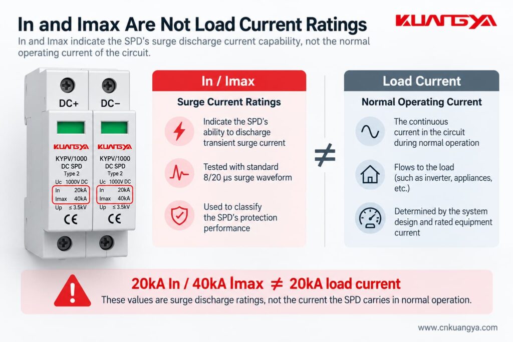
لنفترض أن جهاز الحماية من زيادة التيار (SPD) يحمل العلامات التالية:
In = 20 kA
و
Imax = 40 kA
إذا كانت تصنيفات أجهزة الحماية من زيادة التيار (SPD) هذه لا تزال مربكة، فإن دليل مواصفات أجهزة الحماية من زيادة التيار (SPD) للتيار المستمر (DC) الخاص بنا يشرح Ucpv و In و Imax و Up و Iscpv بمزيد من التفصيل.
هذه الأرقام لا لا تعني أن جهاز الحماية من زيادة التيار (SPD) مصمم لتحمل تيار حمل عادي مستمر قدره 20 كيلو أمبير أو 40 كيلو أمبير.
بالنسبة لأجهزة الحماية من زيادة التيار (SPDs) من النوع 2،, في يشير إلى تيار التفريغ الاسمي المرتبط بنبضة تيار 8/20 ميكروثانية، بينما إيماكس يشير إلى تيار التفريغ الأقصى المرتبط بنبضة 8/20 ميكروثانية.
تصف التعريفات الفنية لشركة Phoenix Contact أيضاً In و Imax كقيم تيار نبضي تتدفق عبر جهاز الحماية من زيادة التيار (SPD)، وليس كقيم تصنيف لتيار الحمل المستمر العادي.
إذن:
In و Imax هما تصنيفان لتيار تفريغ الصواعق، وليسا تيار التشغيل العادي للحمل.
هذا التمييز مهم جداً عند اختيار أو شرح جهاز الحماية من الصواعق (SPD).
لا يوجد.
هذا استثناء مهم.
على الرغم من أن أجهزة الحماية من الصواعق الشائعة من النوع 1 والنوع 2 المذكورة في هذا المقال يتم تركيبها عادةً على التوازي، إلا أن هناك أيضاً وحدات حماية من الصواعق موصلة على التوالي ومرشحات صواعق موصلة على التوالي.
تشير شركة شنايدر إلكتريك إلى أن المنتجات الموصلة على التوالي يتم تركيبها عادةً في الخط بالقرب من أحمال معينة، بينما تعد أجهزة الحماية الموصلة على التوازي هي الترتيب الأكثر شيوعاً في لوحات المفاتيح ولوحات التوزيع.
يجب تصميم المنتج الموصل على التوالي خصيصاً ليتحمل تيار حمل الدائرة.
لذلك، سيكون من غير الصحيح القول:
“لا يمكن أبداً توصيل جهاز الحماية من زيادة التيار (SPD) على التوالي.”
العبارة الأكثر دقة من الناحية الفنية هي:
يتم توصيل معظم أجهزة الحماية من زيادة التيار (SPD) من النوع 1 والنوع 2 الشائعة في أنظمة توزيع الطاقة على التوازي، بينما توجد أيضاً منتجات حماية من زيادة التيار مصممة خصيصاً للتوصيل على التوالي لتطبيقات معينة.
بالنسبة لتطبيقات الطاقة الشمسية الكهروضوئية ولوحات التوزيع العامة، يجب دائماً اتباع مخطط الأسلاك الخاص بالشركة المصنعة لجهاز الحماية من زيادة التيار (SPD).
يوضح الجدول أدناه كيف يختلف جهاز حماية من زيادة التيار (SPD) موصل على التوازي عن الجهاز المثبت مباشرة في مسار تيار الحمل العادي.
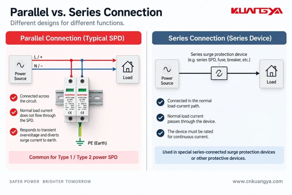
| الميزة | جهاز حماية من اندفاع التيار (SPD) متصل على التوازي | جهاز متصل على التوالي |
|---|---|---|
| متصل مباشرة في مسار الحمل العادي | لا يوجد | نعم |
| يمر تيار الحمل العادي عبر الجهاز بالكامل | لا يوجد | نعم |
| ترتيب شائع لأجهزة الحماية من اندفاع التيار (SPD) من النوع 1 / النوع 2 | نعم | أقل شيوعاً |
| الغرض الرئيسي | يحد من الجهد الزائد العابر عن طريق توفير مسار لتيار الاندفاع | يعتمد على تصميم المنتج |
| التصنيف الحالي المستمر ضروري للجهاز بالكامل | عادة لا يتم ذلك بنفس طريقة الجهاز المدمج في الخط | نعم |
| Installation lead length affects protection | نعم | Internal arrangement may reduce external parallel lead-length effects |
| التطبيقات النموذجية | Distribution boards, equipment entrances, PV systems | Selected sensitive loads or specialized protection/filtering applications |
The important point is not that one method is universally “good” and the other is “bad.”
They are different product architectures.
For a normal DIN-rail power SPD, however, parallel connection is usually the expected installation method.
The same principle applies in many photovoltaic systems, where the SPD is connected in parallel with the DC circuit according to the manufacturer’s wiring configuration.
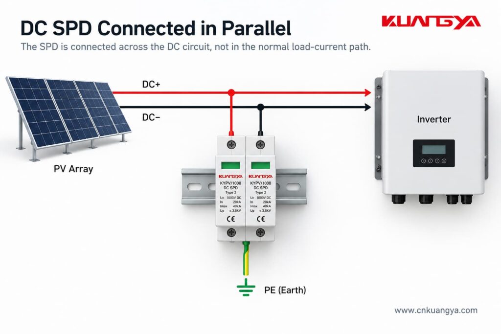
However, DC SPD wiring deserves extra care.
It is not correct to assume that every PV SPD is simply wired:
DC+ → SPD → PE
DC− → SPD → PE
The actual internal protection circuit may be different.
Depending on the product and PV system configuration, the SPD may provide protection modes between:
Different SPD circuit arrangements are used for different earthing systems and PV architectures.
For a PV SPD connected in parallel, the exact terminal arrangement still depends on the SPD design, system topology, and manufacturer wiring diagram.
This is why the wiring diagram printed on the SPD or provided in the manufacturer’s installation instructions is so important.
For photovoltaic DC applications, the dedicated IEC product standard is IEC 61643-31. DEHN also identifies IEC 60364-7-712 and IEC 60364-5-53 among the relevant installation standards for PV and low-voltage SPD applications.
Although AC and DC SPDs are based on similar surge-protection principles, the systems are not interchangeable.
DC systems present additional challenges because direct current has no natural zero crossing, which makes interruption of DC arcs more difficult.
For this reason, the SPD must be specifically suitable for the DC voltage, system configuration and application.
Always check:
before installation.
Using a KUANGYA KYPV/1000 Type 2 DC SPD as an example, the nameplate may include parameters such as:
These values describe different parts of the SPD’s electrical performance.
Uc is the maximum continuous operating voltage specified for the SPD.
The system voltage and possible operating conditions must be considered when choosing a suitable voltage rating.
In is the nominal discharge current.
For a Type 2 SPD, it is associated with an 8/20 μs impulse-current waveform.
Imax is the maximum discharge current specified for the SPD, also associated with the 8/20 μs waveform for this type of device.
Imax is equal to or greater than In.
Up is the voltage protection level.
It indicates the voltage-limiting performance of the SPD under specified test conditions.
The key point for today’s topic is this:
20 kA In and 40 kA Imax do not mean that 20 kA or 40 kA continuously flows through the SPD during normal operation.
These are transient surge-current parameters.
That is another reason why comparing an SPD’s In or Imax directly with the load current of an inverter is incorrect.
لا يوجد.
In fact, connection length is extremely important for a parallel-connected SPD.
A surge has a very fast current rise.
The connecting conductors therefore have inductance, and the rapidly changing surge current can create an additional voltage drop along those conductors.
That additional voltage is effectively added to the voltage experienced by the protected equipment.
وفقاً لـ NEMA’s guidance on hard-wired SPD installation, the size and length of the connecting leads can affect the performance of a parallel-connected SPD, and short, direct connections are preferred.
Phoenix Contact makes the same point: long connecting conductors can increase the effective voltage protection level seen in the installation.
So even if two installations use exactly the same SPD, their real-world protection performance may not be identical if one has much longer connection conductors.
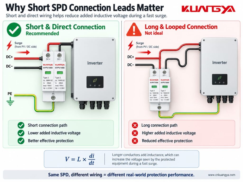
The SPD connection should generally be:
This is also why SPD location matters.
If you want to understand this issue in more detail, see our guide:
هل المسافة بين جهاز الحماية من اندفاع التيار (SPD) والعاكس (Inverter) مهمة؟
The exact position depends on the system being protected.
For example, an SPD may be installed:
If your inverter already includes surge protection, do not assume that an additional external SPD is automatically unnecessary. See العاكس الشمسي يحتوي على جهاز حماية من التيار المستمر (DC SPD) مدمج: هل لا تزال بحاجة إلى جهاز حماية خارجي؟
The objective is not simply to put “one SPD somewhere in the system.”
The SPD should be positioned as part of a coordinated protection concept.
For PV systems in particular, cable length and the location of the inverter, modules and building entry points can affect whether additional SPDs are appropriate.
وفقاً لـ DEHN’s photovoltaic surge protection guidance, SPDs should be installed as close as possible to the equipment being protected, such as the inverter, on both the AC and DC sides.
The specific requirements should always be determined from the applicable installation standard, risk assessment and manufacturer instructions.
Sometimes yes, but not always in exactly the same way.
This is another area where oversimplified advice can cause problems.
A parallel SPD may require an external:
depending on the SPD design and installation.
Other SPDs may include internal protective or disconnecting components.
The correct arrangement depends on factors such as:
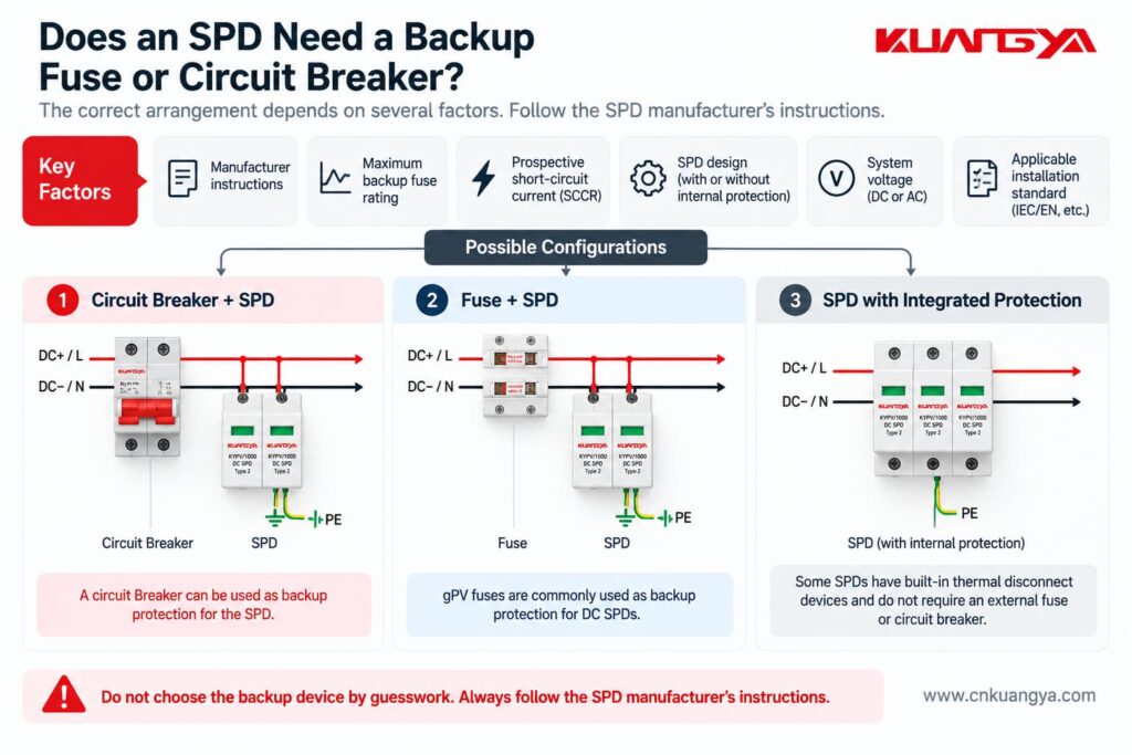
NEMA specifically advises installers to follow the manufacturer’s requirements regarding fuses, breakers and connection leads.
Therefore, do not assume:
“Every SPD needs exactly the same backup breaker.”
And do not assume:
“Because the SPD is connected in parallel, no overcurrent protection is ever required.”
كلا العبارتين قد تكونان خاطئتين.
Always check the SPD datasheet and installation instructions.
Imagine two identical SPDs.
The SPD is mounted very close to the protected equipment, with short and direct conductors.
The SPD is several meters away and connected through long conductors.
Although the SPD nameplate is identical, the effective protection at the equipment can be different.
This happens because the connecting conductors contribute additional inductive voltage during a fast surge.
NEMA explains this relationship using:
V = L × di/dt
where:
The faster the current changes and the more inductance there is in the connection, the greater the additional voltage can become.
You do not need to calculate this formula for every normal installation.
الدرس العملي أبسط بكثير:
Keep SPD connections short and direct.
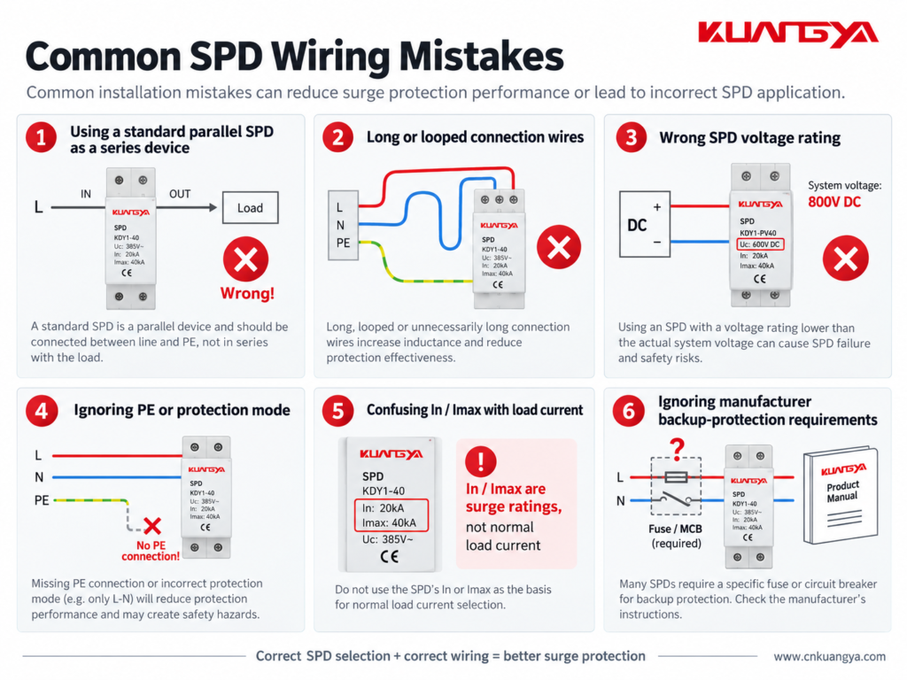
Understanding why the SPD is connected in parallel also makes several common installation mistakes easier to recognize.
Do not simply place a normal parallel DIN-rail SPD in the main load path unless the manufacturer’s design specifically requires that configuration.
Follow the wiring diagram for the exact product.
A good SPD with poor wiring may provide worse protection than expected.
Long leads increase inductive voltage during a surge.
Short and direct routing is generally preferred.
Do not assume every surge simply flows from one line terminal to earth.
The protection modes depend on the electrical network and SPD design.
Correct PE, bonding and circuit connections are essential where required by the product and installation design.
An SPD must be suitable for the voltage that can continuously appear at its terminals.
This is particularly important in PV systems, where string open-circuit voltage changes with temperature.
Choosing an SPD only because it says “DC SPD” is not enough.
The voltage rating must match the actual PV system design.
For a step-by-step method, see our DC SPD voltage selection guide for solar PV systems.
This is one of the most common misunderstandings.
An SPD marked:
In = 20 kA
does not mean:
Normal load current = 20 kA
In and Imax describe surge-current performance under specified impulse conditions.
They are not normal operating-current ratings.
Do not guess the fuse or breaker size.
Different SPD designs can have different backup protection requirements.
Some products also include integrated protective components.
Check the actual product documentation.
Many modular SPDs include a visual status indicator.
If the indicator shows a fault or replacement condition, the protection module may need to be replaced.
Some SPDs also have remote signaling contacts for connection to alarms, PLCs or monitoring systems.
Installing the SPD is only the first step.
Its condition should also be checked during maintenance.
For common warning signs and replacement indicators, see How to Know If an SPD Is Bad?
A circuit breaker and an SPD protect against different electrical problems.
A circuit breaker is mainly intended to interrupt abnormal current conditions such as overloads or short circuits.
Because it must sense and interrupt circuit current, it is connected in series with the load.
An SPD is intended to limit transient overvoltage.
A typical power SPD is connected in parallel so that it can conduct surge current when the transient voltage rises.
That means:
Circuit breaker → current protection
SPD → transient overvoltage protection
One cannot normally replace the other.
They perform different jobs.
The same principle applies to a fuse.
A fuse is installed in series with the circuit it protects.
Normal load current passes through the fuse element.
If excessive current persists, the fuse element opens the circuit.
A typical SPD behaves differently.
It remains connected across the protected circuit and responds mainly when the voltage reaches a level that causes its protective elements to conduct.
So although fuses, breakers and SPDs may all appear in the same electrical panel, their functions and connection methods are not the same.
Most common Type 1 and Type 2 power SPDs used in distribution boards and similar applications are connected in parallel with the circuit they protect.
However, specially designed series-connected SPDs and surge filters also exist.
Always follow the wiring instructions for the exact product.
A typical SPD is connected in parallel because it does not need to carry the normal load current.
During normal voltage conditions, it remains in a high-impedance state.
When a transient overvoltage occurs, it conducts surge current through its protection path and limits the voltage across the protected equipment.
The normal load current does not normally flow through a typical parallel-connected SPD.
However, a small leakage or operating current may exist depending on the SPD technology and design.
Therefore, saying “absolutely no current flows through an SPD” would not be technically precise.
ليس بالضرورة.
An SPD may operate between line and neutral, line and earth, neutral and earth, line and line, or different DC conductors depending on its protection modes.
The exact surge-current path depends on the SPD and electrical system configuration.
Many power SPDs are designed to be connected in parallel across the appropriate conductors of the supply.
However, the exact wiring arrangement depends on the SPD type, system earthing arrangement, required overcurrent protection and manufacturer instructions.
Never determine the connection from a generic diagram alone.
A normal parallel SPD is not designed to serve as the continuous main load-current path.
Installing an inline device requires a product specifically designed for that purpose, including suitable current, terminal, fault and thermal ratings.
لا يوجد.
In and Imax are surge-discharge current parameters.
They should not be confused with PV string operating current, short-circuit current or inverter input current.
The general surge-protection principle is similar, but DC and AC systems have important differences.
The voltage rating, polarity, protection modes, earthing arrangement and internal SPD design may differ.
For PV systems, always use an SPD intended for the specific DC application and follow its wiring diagram.
It depends on the protection mode and system design.
Many power SPDs include protection paths involving PE, but not every surge protection mode is simply conductor-to-earth.
Use the manufacturer’s circuit diagram and the applicable earthing and bonding requirements.
نعم.
Long SPD connection conductors add inductance and can increase the voltage experienced by the protected equipment during a fast transient.
For this reason, connection conductors should generally be kept as short and direct as practical.
If you only remember a few things from this article, remember these:
So, why is an SPD connected in parallel instead of series?
For a typical Type 1 or Type 2 جهاز حماية من زيادة التيار (SPD) موصل على التوازي, the normal load current does not pass through the SPD as it would through a series-connected device.
Under normal operating conditions, the SPD remains largely in standby.
When a surge occurs, it conducts through its designed protection path and helps limit the voltage appearing across the protected equipment.
That is fundamentally different from a fuse or circuit breaker, which normally carries the circuit current and is therefore installed in series.
However, correct SPD installation involves more than simply choosing “parallel.”
The SPD voltage rating, protection modes, location, conductor length, earthing and bonding arrangement, backup protection and manufacturer wiring diagram all affect the final protection performance.
For solar PV systems in particular, always use an SPD designed for the relevant DC application and verify the actual system voltage and wiring configuration before installation.

