منطقة ونغ يانغ الصناعية يويتشينغ ونتشو 325000
ساعات العمل
من الاثنين إلى الجمعة: 7 صباحاً - 7 مساءً
عطلة نهاية الأسبوع 10 صباحاً - 5 مساءً
منطقة ونغ يانغ الصناعية يويتشينغ ونتشو 325000
ساعات العمل
من الاثنين إلى الجمعة: 7 صباحاً - 7 مساءً
عطلة نهاية الأسبوع 10 صباحاً - 5 مساءً

هل يمكن لجهاز الحماية من زيادة التيار (SPD) العمل بدون تأريض؟ الإجابة الصحيحة تقنياً هي: في بعض الأحيان يمكن لوضع حماية معين أن يعمل بدون مسار مباشر لخط التأريض (PE)، ولكن هذا لا يعني أن نظام الحماية من زيادة التيار بالكامل محمي بشكل صحيح بدون تأريض أو ربط.
لا يقوم جهاز الحماية من زيادة التيار ببساطة “بإرسال كل زيادة في التيار إلى التربة”. بل يعمل على تحديد الجهد بين الموصلات المحددة عن طريق التحول إلى حالة التوصيل عندما يرتفع الجهد عبر وضع الحماية فوق نطاق تشغيله. واعتماداً على تصميم جهاز الحماية من زيادة التيار، قد تشمل أوضاع الحماية هذه: الخط إلى المحايد (L–N)، أو الخط إلى الأرضي الوقائي (L–PE)، أو المحايد إلى الأرضي الوقائي (N–PE)، أو التيار المستمر الموجب/السالب إلى الأرضي (DC+/DC− to PE).
لهذا السبب فإن السؤال أكثر تعقيداً من مجرد “مؤرض أم غير مؤرض”. الأسئلة الهندسية الحقيقية هي:
إذا كانت المشكلة التي تحاول حلها ليست التأريض بل الفرق بين الارتفاع المفاجئ في الجهد ومشكلة الجهد طويل الأمد، فاقرأ أولاً هل يحمي جهاز الحماية من زيادة التيار (SPD) من الجهد الزائد؟. لا يمكن للتأريض أن يحول جهاز الحماية من زيادة التيار (SPD) إلى منظم جهد أو مرحل جهد زائد عام.
هل يمكن لجهاز الحماية من اندفاع التيار (SPD) العمل بدون تأريض؟ الإجابة الأدق هي: يعتمد ذلك على المقصود بـ “التأريض” وعلى نمط حماية جهاز SPD الذي تتم مناقشته.
| الوضع | هل لا يزال بإمكان جهاز SPD القيام بأي وظيفة؟ | الشاغل الرئيسي |
|---|---|---|
| نمط الحماية بين الخط والمحايد (L–N) مع عدم وجود توصيل مباشر بالأرضي الوقائي (PE) في هذا النمط | من المحتمل نعم | يتم تحديد جهد النمط التفاضلي فقط بين الخط (L) والمحايد (N) |
| نمط الحماية بين الخط والأرضي (L–PE) أو بين المحايد والأرضي (N–PE) مع فقدان توصيل الأرضي الوقائي (PE) | ليس كما هو مقصود | مسار الحماية المصمم غير مكتمل أو غير صحيح |
| موصل التأريض الوقائي (PE) موجود ولكن التوصيلة طويلة بشكل مفرط | قد يظل جهاز الحماية من اندفاع التيار (SPD) يعمل | الجهد التحريضي الإضافي قد يؤدي إلى زيادة مستوى الحماية المثبت |
| جهاز حماية من اندفاع التيار (SPD) غير مناسب لنظام التأريض TN/TT/IT | لا تفترض وجود حماية صحيحة | قد لا تتوافق أوضاع الحماية، وإجهاد الجهد الزائد المؤقت (TOV)، وظروف الأعطال مع النظام |
| نظام طاقة شمسية كهروضوئية عائم بتيار مستمر | نعم، مع وجود ترتيب صحيح ومصمم لأجهزة الحماية من زيادة التيار (SPD) الخاصة بالنظام الكهروضوئي | “التيار المستمر العائم” لا يعني إمكانية تجاهل التأريض الوقائي (PE) وربط تساوي الجهد |
| عدم وجود ربط فعال / تلف في توصيلة التأريض الوقائي (PE) | قد تتعرض الحماية لخطر جسيم | قد تظل هناك فروق في الجهد بين الأنظمة الموصلة |
القاعدة الأهم هي:
لا تقرر ما إذا كان جهاز الحماية من زيادة التيار (SPD) “يحتاج إلى تأريض” بمجرد النظر إلى عدد الوحدات. حدد نظام تأريض الشبكة وأنماط الحماية الفعلية للجهاز.
هذا هو نفس السبب الذي يجعل اختيار جهاز حماية من اندفاع التيار (SPD) ثنائي القطب (2P) أو ثلاثي القطب (3P) للطاقة الشمسية لا ينبغي أن يعتمد على المظهر فقط. دليل المقارنة بين أجهزة الحماية من اندفاع التيار المستمر (DC SPD) ثنائية القطب (2P) وثلاثية القطب (3P) يوضح لماذا تعتبر أعداد الوحدات، والموصلات المحمية، وتوصيل التأريض (PE)، ومسارات الحماية الداخلية مفاهيم مختلفة.
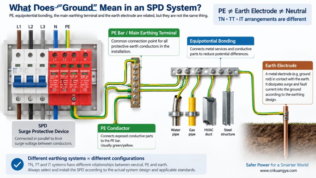
قبل الإجابة على سؤال “هل يمكن لجهاز الحماية من اندفاع التيار (SPD) العمل بدون أرضي؟”، نحتاج أولاً إلى تحديد ما يعنيه “الأرضي” فعلياً في التركيبات الكهربائية.
في المحادثات اليومية، قد يشير مصطلح “الأرضي” إلى عدة أشياء مختلفة:
PE هو الموصل الوقائي المستخدم لتوصيل الأجزاء الموصلة المكشوفة بنظام الربط الوقائي للتركيبات الكهربائية. تتضمن العديد من أجهزة الحماية من زيادة التيار (SPDs) أوضاع حماية تعتمد على التأريض (PE).
هذه هي نقطة الربط داخل التركيب أو مجمع التوزيع حيث يتم توصيل الموصلات الوقائية وفقاً لتصميم النظام.
يوفر قطب التأريض اتصالاً موصلاً بين التركيبات الكهربائية والأرض. وهو جزء من نظام التأريض، ولكن لا ينبغي الخلط بينه وبين توصيلة PE القصيرة بين جهاز حماية من اندفاع التيار (SPD) وقضيب PE المحلي.
يقلل الربط من فروق الجهد الخطيرة بين الأجزاء الموصلة والخدمات. أثناء حدوث اندفاع في التيار، غالباً ما يكون التحكم في فروق الجهد أكثر أهمية من تصور تيار الاندفاع على أنه يسلك مساراً واحداً بسيطاً “عبر سلك أرضي”.”
تعتمد العلاقة بين المحايد والأرضي على نظام التأريض. لا تستخدم أنظمة TN وTT وIT نفس ترتيب المحايد/PE، وهذا أحد الأسباب التي تجعل من غير المفترض أن تكون طوبولوجيا SPD نفسها مناسبة في كل مكان.
تميز توجيهات ABB العملية الخاصة بأجهزة حماية التيار (SPD) بين أنظمة التأريض TT وTN-C وTN-S وIT وفقاً لكيفية ارتباط المحايد الخاص بالتغذية وأرضي المعدات. لذلك، يجب تنسيق اختيار جهاز حماية التيار (SPD) مع النظام الكهربائي الفعلي بدلاً من الاعتماد على قاعدة “سلك أرضي” عالمية.
يتم توصيل جهاز الحماية من زيادة التيار (SPD) النموذجي على التوازي مع الدائرة بدلاً من حمل تيار التشغيل العادي على التوالي. في الظروف العادية، تظل عناصر الحماية من زيادة التيار في حالة مقاومة عالية. وعندما يرتفع الجهد عبر وضع الحماية بشكل كافٍ، يصبح جهاز الحماية موصلاً للكهرباء ويقوم بتحديد الجهد عن طريق تحويل تيار الزيادة عبر مسار الحماية ذلك.
إذا كنت ترغب في الحصول على شرح على مستوى الدائرة أولاً، راجع لماذا يتم توصيل جهاز الحماية من زيادة التيار (SPD) على التوازي بدلاً من التوالي.
عبارة “تحويل تيار الزيادة إلى الأرض” يعد شرحاً مبسطاً ومفيداً، ولكنه قد يؤدي أيضاً إلى سوء فهم. فليست كل زيادة في التيار يتم التعامل معها بواسطة موصل واحد يمتد مباشرة إلى قضيب التأريض.
ضع في اعتبارك أوضاع الحماية الثلاثة الشائعة:
| وضع الحماية | الجهد الذي يتم تحديده | هل يستخدم هذا النمط خط التأريض الوقائي (PE) مباشرة؟ |
|---|---|---|
| L–N | الخط بالنسبة للمحايد | لا يلزم وجود طرف توصيل مباشر للتأريض الوقائي (PE) لهذا النمط الفردي |
| L–PE | الخط بالنسبة للتأريض الوقائي | نعم |
| N–PE | المحايد بالنسبة للتأريض الوقائي | نعم |
| DC+–PE / DC −–PE | موصلات الطاقة الكهروضوئية بالنسبة إلى موصل التأريض الوقائي (PE) | نعم |
هذا هو مفتاح فهم السؤال.
قد يقوم عنصر الحماية بين الخط والمحايد (L–N) بتثبيت الجهد التفاضلي بين الخط والمحايد حتى لو لم يكن ذلك العنصر متصلاً مباشرة بموصل التأريض الوقائي (PE). ولكن إذا كانت التركيبة تتطلب أيضاً حماية ضد جهد الاندفاع في النمط المشترك بالنسبة إلى موصل التأريض الوقائي (PE)، فإن مسار (L–N) وحده لا يغني عن أنماط الحماية المطلوبة المرتبطة بموصل التأريض الوقائي (PE) ونظام الربط.
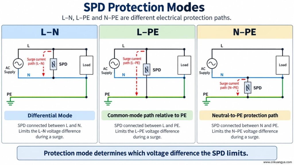
هل يمكن لجهاز الحماية من الاندفاعات (SPD) العمل بدون أرضي أو موصل تأريض وقائي (PE)؟ إذا كان جهاز الحماية من الاندفاعات (SPD) يحتوي فقط على نمط حماية بين الموصلات النشطة، فقد يستجيب هذا النمط لفرق الجهد بين تلك الموصلات. ولكن نمط الحماية الذي يعتمد على موصل التأريض الوقائي (PE) لا يمكنه العمل كما هو مصمم له إذا كان اتصال (PE) مفقوداً.
هذا يعني أن العبارتين يمكن أن تكونا صحيحتين في آن واحد:
لذلك، لا تقم أبداً بإزالة أو تجاوز أو الارتجال في توصيلة التأريض الوقائي (PE) لمجرد أن جهاز الحماية من زيادة التيار (SPD) لا يزال يظهر مؤشر حالة أخضر.
تشير نافذة الحالة عادةً إلى حالة آلية داخلية مراقبة. وهي لا تثبت وجود موصل التأريض الوقائي (PE) الخارجي، أو أن نظام الربط صحيح، أو أن طول التوصيلة مقبول.
إذا تم تصميم جهاز الحماية من زيادة التيار (SPD) بمسارات حماية (L–PE) أو (N–PE) أو (DC+–PE) أو (DC−–PE) وأصبح توصيل التأريض الوقائي (PE) مفتوحاً، فإن تلك الأنماط لن تعود متصلة بالتوصيلة الخارجية المقصودة.
تشمل العواقب المحتملة ما يلي:
إن فقدان الموصل الوقائي ليس اختصاراً لاستكشاف أخطاء جهاز الحماية من التموجات (SPD) وإصلاحها. يجب فحص التركيبات وتصحيحها بواسطة شخص مؤهل وفقاً لتعليمات المعدات والقواعد الكهربائية المعمول بها.
تتغير الإجابة على سؤال “هل يمكن لجهاز الحماية من التموجات (SPD) العمل بدون تأريض؟” لأن بنية التأريض تختلف في أنظمة TN وTT وIT.
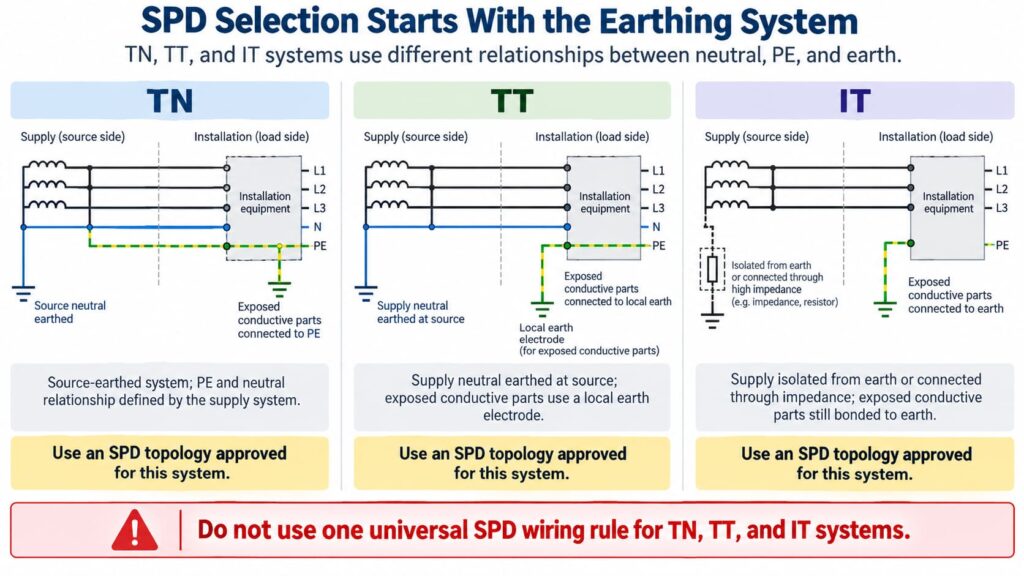
في ترتيب نظام TN-S، يكون المحايد (Neutral) وخط التأريض الوقائي (PE) موصلين منفصلين في التمديدات الكهربائية. يجب اختيار جهاز الحماية من زيادة التيار (SPD) وتوصيله بما يتناسب مع تكوين النظام المعني وأنماط الحماية المطلوبة.
In TN-C-S systems, the upstream PEN conductor is divided into separate N and PE at a defined point. An SPD installed on the TN-S part must be suitable for that part of the system. The exact connection arrangement should follow the product instructions and local requirements.
Do not create an extra neutral-to-earth link beside the SPD as an improvised “better ground.” Neutral/PE bonding is a system-design issue, not a field modification to improve SPD performance.
In a TT system, the installation’s exposed conductive parts are connected to a local earth electrode while the supply neutral has its own source earthing arrangement.
This affects SPD topology, protection modes, temporary overvoltage behavior, and coordination with protective devices. Depending on the design, manufacturers often provide specific TT-compatible SPD arrangements rather than treating a TN model as universally interchangeable.
The correct question is therefore not “Does TT have a ground rod?” but:
Is this SPD and its connection arrangement specifically suitable for the TT system at this installation point?
In an IT system, the supply may be isolated from earth or connected to earth through an impedance, while exposed conductive parts remain earthed according to the installation design.
This creates different voltage conditions, especially during a first insulation fault. An SPD used in an IT system must therefore be explicitly suitable for that system and for the possible continuous and temporary voltages it can experience.
Do not choose an SPD for an IT system solely because its Uc value appears high enough.
For AC SPDs, IEC 61643-11:2025 specifies performance and safety requirements for SPDs connected to AC low-voltage power systems. System selection and installation still require coordination with the actual network and installation rules. See the IEC 61643-11:2025 publication page.
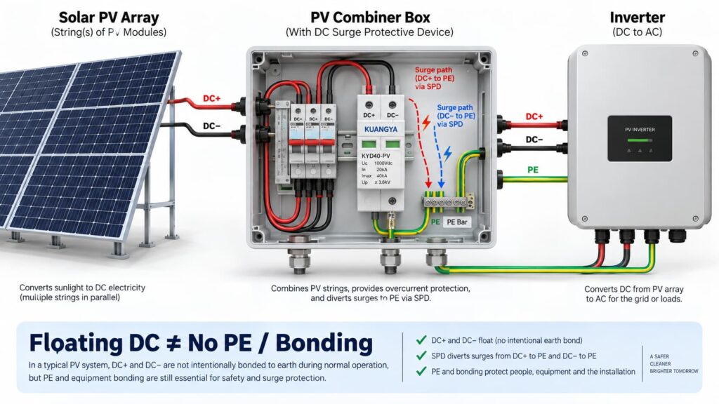
In solar PV systems, the question “can an SPD work without ground?” becomes even more complicated because the DC circuit may be intentionally floating.
Many PV DC circuits operate with neither DC+ nor DC− intentionally bonded directly to earth during normal operation. This is often described as a floating or unearthed DC array.
But that does لا mean the whole PV installation has no protective earth, bonding or surge path to PE.
A PV SPD may provide coordinated protection between:
Some PV SPDs use a Y-type internal circuit specifically intended for photovoltaic applications. The correct arrangement depends on the inverter topology, PV earthing arrangement, maximum PV voltage, insulation-monitoring concept and the manufacturer’s approved circuit.
This is why a floating PV system can still use a PE-connected SPD arrangement.
IEC 61643-31 applies to SPDs intended for the DC side of photovoltaic installations up to 1500 V DC and covers their performance characteristics, safety requirements, test methods and ratings. See the IEC 61643-31 publication page.
Before selecting a PV SPD, also verify Ucpv, In, Imax, Up and Iscpv. Our دليل مواصفات أجهزة الحماية من زيادة التيار (SPD) للتيار المستمر (DC) الخاص بنا explains what these markings mean and why the largest kA number is not enough.
لا يوجد.
A 2P or 3P description does not automatically tell you:
For the same reason, AC module count can also be misleading. If you are comparing neutral/PE arrangements, see our مقارنة بين 3+1 و 4+0 لأجهزة الحماية من اندفاع التيار (SPD).
An SPD can be correctly selected and correctly connected to PE, yet still provide poorer installed protection because the connection conductors are too long.
The reason is conductor inductance.
During a fast-rising surge current, additional voltage develops across the SPD connecting conductors:
ΔU = L × di/dt
أين:
This means the equipment does not necessarily see only the SPD’s datasheet voltage protection level Up. The installed voltage can also include voltage developed across the connection path.
Schneider Electric’s Electrical Installation Guide recommends keeping the total SPD connection length to the network and earth terminal block at no more than approximately 50 cm in the illustrated arrangement and explains the added inductive voltage created by longer conductors. See its SPD connection guidance.
The current consolidated IEC installation standard is IEC 60364-5-53:2019 + Amendment 1:2020 + Amendment 2:2024, which includes Clause 534 for surge protective devices. See the IEC 60364-5-53 consolidated publication page.
If you want a deeper explanation of why conductor length matters during a surge, read our guide on SPD distance from the inverter and connection lead length.
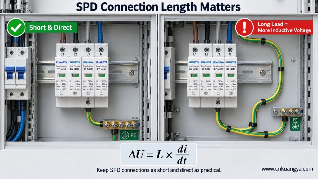
So when asking whether an SPD can work without ground, the quality and length of the PE connection are just as important as whether a protective-earth conductor is physically present.
Trying to reduce lead length by bypassing the approved panel bonding arrangement and connecting an SPD to a separate, isolated earth electrode can create a different problem: the installation may no longer be equipotentially bonded as required.
The correct objective is not “find the nearest piece of earth.”
بل هو:
Connect the SPD to the manufacturer-specified PE/bonding point using the shortest practical, low-impedance path permitted by the system design.
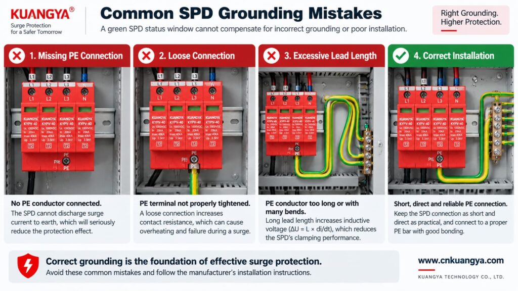
Poor grounding is not one single failure mode. The effect depends on what is actually wrong.
| المشكلة | Possible Effect | ما الذي يجب التحقق منه |
|---|---|---|
| PE conductor missing | PE-dependent protection modes may not function as intended | Wiring diagram, PE continuity, bonding arrangement |
| Loose PE terminal | Unstable/high-impedance surge path, heating or arcing risk under fault conditions | Terminal condition and specified torque |
| Very long SPD connection | Higher installed residual voltage due to inductive voltage | Lead length and routing |
| Large conductor loop | Higher inductive coupling and loop impedance | Routing and loop area |
| Wrong TN/TT/IT SPD topology | Incorrect protection modes or unsuitable voltage stress | System earthing arrangement and manufacturer approval |
| Unbonded conductive systems | Dangerous transient potential differences may remain | Equipotential bonding of incoming services and installation |
| Green SPD indicator but external wiring fault | False confidence | Inspect the complete installation, not only the indicator |
Not by itself.
This is another important distinction.
A low measured earth-electrode resistance can be useful for the earthing system, but SPD performance during a fast transient also depends heavily on:
Therefore, a long conductor to an excellent earth electrode can still develop significant transient voltage during a steep surge current.
For surge protection, think in terms of impedance and equipotential bonding, not only DC or low-frequency resistance.
Can an SPD work without ground when it only protects L–N? It may limit the voltage between L and N if that is an approved protection mode of the device.
However, three cautions are essential.
If a surge raises both L and N relative to PE, an L–N element may see relatively little differential voltage even though the equipment is experiencing a large common-mode voltage relative to earth.
Electronic equipment can have chassis connections, signal cables, communication ports, antennas, shields or other conductive interfaces that create additional surge paths.
Do not intentionally leave a PE terminal disconnected on an SPD that is designed to use it. The correct wiring diagram is part of the product’s protection concept.
A backup fuse or circuit breaker does not replace grounding.
Likewise, grounding does not replace backup overcurrent protection where the SPD manufacturer requires it.
| Component / Function | Main Role |
|---|---|
| SPD | Limits transient overvoltage and diverts surge current through defined protection modes |
| PE / bonding system | Provides protective bonding and reference/discharge paths according to the installation design |
| Backup fuse or circuit breaker | Helps isolate fault current according to the SPD manufacturer’s coordination requirements |
| Earth electrode | Connects the installation earthing system to earth |
| Voltage protection relay / regulator | Addresses longer-duration abnormal voltage depending on device type |
If you are selecting upstream protection, see our practical guide: does an SPD need a backup fuse or circuit breaker?
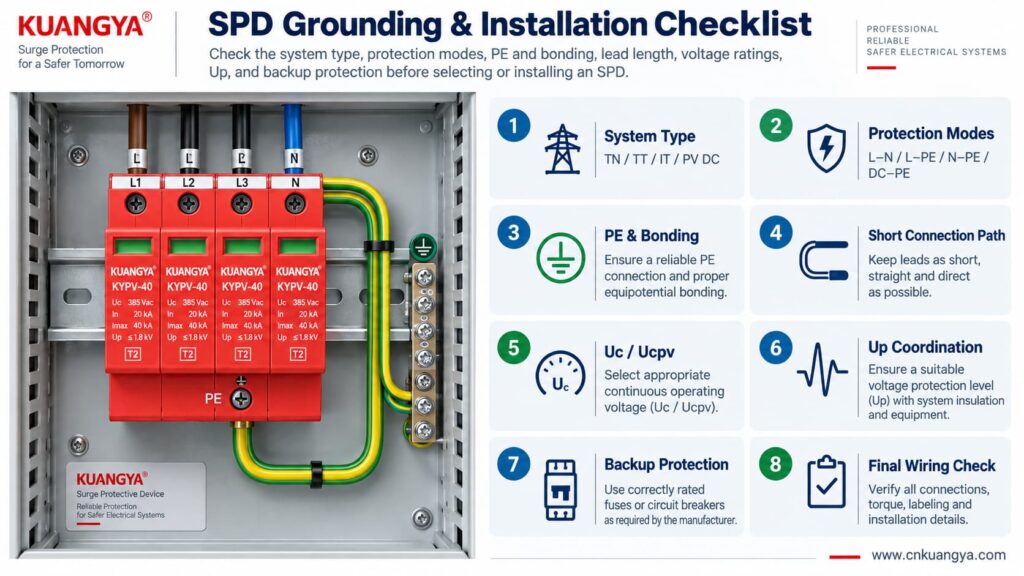
Use the following sequence as a design and inspection checklist. It is not a substitute for local electrical rules or the manufacturer’s instructions.
Confirm whether the circuit is:
Read the internal circuit or wiring diagram, not only the product front label.
Look for protection paths such as L–N, L–PE, N–PE, L1/L2/L3 relationships, DC+–PE and DC−–PE.
Connect only to the approved PE or bonding terminal shown by the manufacturer and installation design.
Avoid unnecessary conductor loops, coils and wide separation between surge-current paths.
For AC, confirm Uc and the applicable system voltage. For PV, confirm Ucpv against the maximum possible PV voltage, including cold-weather Voc where relevant.
Remember that installed protection depends on both the SPD’s Up and the voltage contribution of the connecting conductors.
Verify the manufacturer’s maximum backup fuse / circuit-breaker requirements and the prospective short-circuit conditions.
If an inverter already contains an SPD, do not assume external surge protection is unnecessary. Cable distance, system architecture and the location of the built-in SPD still matter. See our guide on solar inverter built-in SPD and external SPD requirements.
Before deciding whether an SPD can work without ground in a real installation, check the complete protection system rather than judging the SPD alone.
| تحقق | سؤال | ما أهمية ذلك |
|---|---|---|
| نظام | TN, TT, IT, AC or PV DC? | Determines compatible SPD topology |
| Protection modes | Which conductor pairs are protected? | Shows what voltage differences the SPD can limit |
| توصيل التأريض (PE) | Is PE required and correctly connected? | Essential for PE-dependent protection modes |
| Bonding | Are relevant conductive systems equipotentially bonded? | Reduces dangerous transient potential differences |
| Lead length | Are SPD connections as short and direct as practical? | Reduces added inductive voltage |
| الفولتية | Is Uc / Ucpv correct? | Avoids continuous overvoltage stress |
| Protection level | Is Up coordinated with the equipment? | Determines residual voltage stress |
| Surge rating | Are In, Imax and/or Iimp suitable? | Matches expected surge duty |
| Short-circuit conditions | Are SCCR / Iscpv and backup protection suitable? | Important for safe failure and isolation |
| Manufacturer diagram | Does the installed wiring match the approved circuit? | Prevents topology mistakes |
For photovoltaic projects, KUANGYA provides أجهزة الحماية من زيادة التيار المستمر for different PV voltage classes and installation requirements. Final model selection should always be based on the actual PV voltage, earthing arrangement, protection mode, SPD type and system fault conditions.
Sometimes an individual protection mode such as L–N can operate without a direct PE connection. However, that does not mean the complete surge-protection system can ignore PE, earthing or equipotential bonding. Any SPD mode designed to operate between a live conductor and PE requires the intended PE connection.
When people ask “can an SPD work without ground?”, the answer depends on the SPD circuit rather than on one universal rule. Some devices or protection modes operate only between active conductors, while many power SPDs include PE-related protection modes. Follow the manufacturer’s circuit diagram and select the SPD for the actual TN, TT, IT or DC/PV system.
The SPD may still operate, but a long connection can add inductive voltage during a fast-rising surge current. This can increase the voltage that appears at the protected equipment. Short, direct connections are therefore an important part of SPD installation.
Do not improvise an isolated grounding path simply to make the SPD conductor shorter. The SPD should be connected to the approved PE/bonding point in accordance with the system design, manufacturer instructions and applicable electrical rules.
Not by itself. Surge performance also depends on high-frequency impedance, connection length, conductor routing, loop area, bonding and the SPD’s protection characteristics. A low earth-electrode resistance does not compensate for poor SPD wiring.
Yes. A PV DC system may have neither polarity intentionally grounded during normal operation while still using a properly designed SPD arrangement with protection paths to PE. Use a PV SPD approved for that topology and voltage.
No. A status indicator normally reports the condition of the SPD’s internal monitoring or disconnection mechanism. It does not verify external PE continuity, bonding, conductor length or correct earthing-system selection.
No. An SPD and the installation’s protective-earthing/bonding system perform different functions. A surge protective device should be considered part of a coordinated electrical protection system, not a replacement for protective earthing.
Grounding and bonding are fundamental parts of electrical safety and lightning/surge protection, but they do not perform the same voltage-limiting function as an SPD at equipment terminals. A complete design may require both, depending on the installation.
There is no single standard that answers every installation question. IEC 61643-11 covers AC low-voltage SPD product requirements, IEC 61643-31 covers PV DC SPD product requirements, and IEC 60364-5-53 includes installation requirements for low-voltage electrical installations, including Clause 534 for SPDs. Project-specific lightning-protection and national wiring requirements may also apply.
هل يمكن لجهاز الحماية من اندفاع التيار (SPD) العمل بدون تأريض؟ The answer cannot be reduced to a simple yes or no.
An SPD limits voltage across specific protection modes. A mode between active conductors, such as L–N, may operate without directly using PE. But any protection mode that depends on L–PE, N–PE, DC+–PE or DC−–PE requires the designed PE/bonding path.
More importantly, surge protection is a system function.
A correctly selected SPD can still perform poorly if:
For that reason, do not ask only:
“Does this SPD have a ground terminal?”
Ask instead:
“What voltage differences must be limited, what protection modes does this SPD provide, and how is the complete system bonded and earthed?”
That question leads to a much safer and more technically correct SPD selection.
Technical note: This article is intended for product selection and engineering education. Actual SPD installation must follow the device manufacturer’s wiring instructions, the applicable electrical installation standard, and local code requirements.

