Zone industrielle WengYang Yueqing Wenzhou 325000
Heures de travail
Du lundi au vendredi : de 7h00 à 19h00
Le week-end : 10H00 - 17H00
Zone industrielle WengYang Yueqing Wenzhou 325000
Heures de travail
Du lundi au vendredi : de 7h00 à 19h00
Le week-end : 10H00 - 17H00

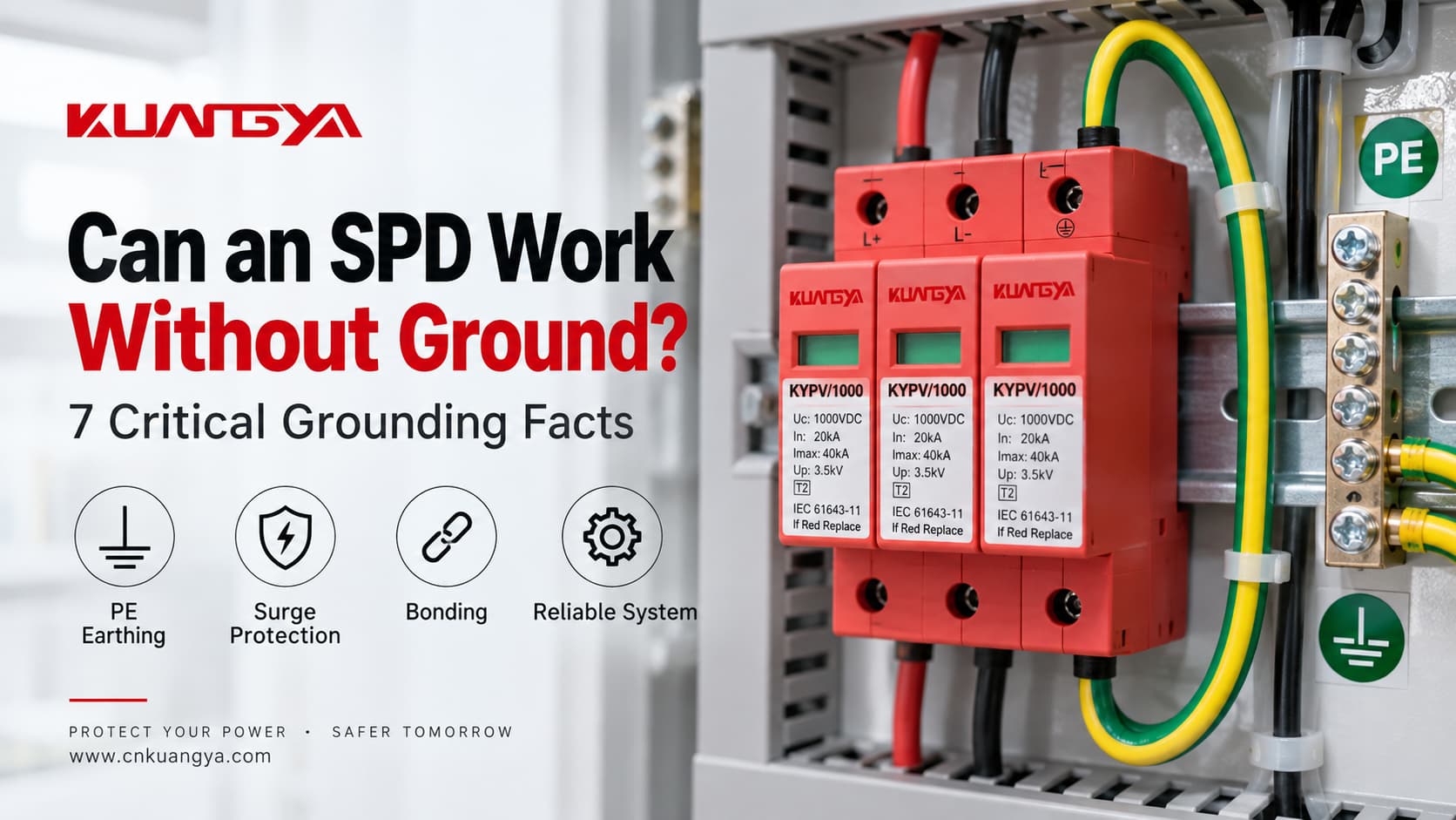
Un parafoudre peut-il fonctionner sans terre ? La réponse techniquement correcte est : parfois, un mode de protection spécifique peut fonctionner sans chemin PE direct, mais cela ne signifie pas que le système complet de protection contre les surtensions est correctement protégé sans mise à la terre ou liaison équipotentielle.
Un parafoudre ne se contente pas d“” envoyer chaque surtension dans le sol ». Il limite la tension entre des conducteurs définis en devenant conducteur lorsque la tension aux bornes d'un mode de protection dépasse sa plage de fonctionnement. Selon la conception du parafoudre, ces modes de protection peuvent inclure phase-neutre (L–N), phase-terre (L–PE), neutre-terre (N–PE), ou DC+/DC− vers la terre (PE).
C'est pourquoi la question est plus complexe qu'un simple “ mis à la terre ou non ”. Les véritables questions d'ingénierie sont :
Si le problème que vous tentez de résoudre n'est pas lié à la mise à la terre, mais à la différence entre une surtension transitoire et un problème de tension de plus longue durée, lisez d'abord un parafoudre protège-t-il contre les surtensions. La mise à la terre ne peut pas transformer un parafoudre en régulateur de tension ou en relais de surtension général.
Un parafoudre peut-il fonctionner sans mise à la terre ? Une meilleure réponse est : cela dépend de ce que l'on entend par “ terre ” et du mode de protection du parafoudre concerné.
| Situation | Le parafoudre peut-il encore agir ? | Préoccupation principale |
|---|---|---|
| Mode de protection L-N sans connexion directe à la terre (PE) dans ce mode | Potentiellement oui | Seule la tension en mode différentiel entre L et N est limitée |
| Mode de protection L-PE ou N-PE avec absence de PE | Non conforme à l'usage prévu | Le chemin de protection conçu est incomplet ou incorrect |
| Le conducteur PE existe mais la connexion est excessivement longue | Le parafoudre (SPD) peut toujours fonctionner | Une tension inductive supplémentaire peut augmenter le niveau de protection installé |
| SPD inadapté au système de mise à la terre TN/TT/IT | Ne pas présumer d'une protection correcte | Les modes de protection, les contraintes TOV et les conditions de défaut peuvent ne pas correspondre au système |
| Système photovoltaïque CC flottant | Oui, avec une configuration de parafoudre PV correctement conçue | “ CC flottant ” ne signifie pas que la mise à la terre (PE) et la liaison équipotentielle peuvent être ignorées |
| Absence de liaison efficace / connexion PE endommagée | La protection peut être gravement compromise | Des différences de potentiel peuvent subsister entre les systèmes conducteurs |
La règle la plus importante est :
Ne décidez pas si un parafoudre “ a besoin d'une mise à la terre ” en regardant uniquement le nombre de modules. Identifiez le schéma de liaison à la terre du système et les modes de protection réels du parafoudre.
C'est pour cette même raison qu'un parafoudre PV 2P ou 3P ne doit pas être sélectionné uniquement sur son apparence. Notre Guide comparatif des parafoudres DC 2P vs 3P explique pourquoi le nombre de modules, les conducteurs protégés, la connexion PE et les chemins de protection internes sont des concepts différents.
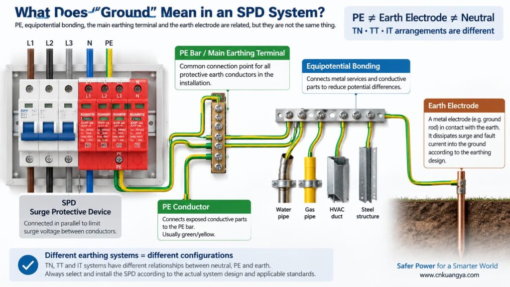
Avant de répondre à la question “ un parafoudre peut-il fonctionner sans terre ? ”, nous devons d'abord définir ce que signifie réellement “ terre ” dans une installation électrique.
Dans le langage courant, “ terre ” peut désigner plusieurs choses différentes :
Le conducteur de protection (PE) est utilisé pour relier les masses conductrices au système de liaison équipotentielle de l'installation électrique. De nombreux parafoudres incluent des modes de protection référencés au PE.
Il s'agit du point de liaison à l'intérieur de l'installation ou de l'ensemble de distribution où les conducteurs de protection sont connectés conformément à la conception du système.
Une prise de terre assure une connexion conductrice entre l'installation électrique et la terre. Elle fait partie du système de mise à la terre, mais ne doit pas être confondue avec la courte connexion PE entre un parafoudre (SPD) et la barre PE locale.
La liaison équipotentielle réduit les différences de potentiel dangereuses entre les parties conductrices et les services. Lors d'un événement de surtension, le contrôle des différences de potentiel est souvent plus important que de considérer le courant de surtension comme empruntant un simple chemin “ vers un fil de terre ”.”
La relation entre le neutre et la terre dépend du schéma de liaison à la terre (régime de neutre). Les systèmes TN, TT et IT n'utilisent pas la même disposition neutre/PE, ce qui explique pourquoi une même topologie de parafoudre ne peut être considérée comme adaptée partout.
Les conseils pratiques d'ABB sur les parafoudres distinguent les systèmes de mise à la terre TT, TN-C, TN-S et IT selon la manière dont le neutre d'alimentation et les terres des équipements sont reliés. Le choix du parafoudre doit donc être coordonné avec le système électrique réel plutôt que basé sur une règle universelle de “ fil de terre ”.
Un parafoudre (SPD) typique est connecté en parallèle avec le circuit plutôt que de transporter le courant de charge normal en série. Dans des conditions normales, ses éléments de protection contre les surtensions restent dans un état à haute impédance. Lorsque la tension aux bornes d'un mode de protection augmente suffisamment, le SPD devient conducteur et limite la tension en dérivant le courant de surtension à travers ce chemin de protection.
Si vous souhaitez d'abord obtenir l'explication au niveau du circuit, voir pourquoi un SPD est connecté en parallèle plutôt qu'en série.
L'expression “ dériver le courant de surtension vers la terre ” est utile comme explication simplifiée, mais cela peut aussi créer un malentendu. Chaque surtension n'est pas traitée par un seul conducteur relié directement à un piquet de terre.
Considérez trois modes de protection courants :
| Mode de protection | Tension limitée | Ce mode utilise-t-il directement le PE ? |
|---|---|---|
| L–N | Phase par rapport au neutre | Aucune borne PE directe n'est requise pour ce mode individuel |
| L–PE | Phase par rapport à la terre de protection | Oui |
| N–PE | Neutre par rapport à la terre de protection | Oui |
| DC+–PE / DC−–PE | Conducteurs PV par rapport à la terre (PE) | Oui |
C'est la clé pour comprendre la question.
Un élément de protection L-N peut toujours écrêter la tension différentielle entre la phase et le neutre, même si cet élément spécifique n'est pas connecté directement à la terre (PE). Cependant, si l'installation nécessite également une protection contre les surtensions en mode commun par rapport à la terre (PE), un chemin L-N seul ne remplace pas les modes de protection requis liés à la terre ni le système de liaison équipotentielle.
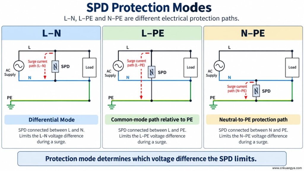
Un parafoudre peut-il fonctionner sans mise à la terre ou conducteur de protection (PE) ? Si le parafoudre ne possède qu'un mode de protection entre conducteurs actifs, ce mode peut toujours réagir à une différence de tension entre ces conducteurs. Mais un mode de protection dépendant de la terre (PE) ne peut pas fonctionner comme prévu si sa connexion à la terre est absente.
Cela signifie que deux affirmations peuvent être vraies simultanément :
Par conséquent, ne jamais supprimer, contourner ou improviser la connexion PE simplement parce qu'un parafoudre affiche un indicateur d'état vert.
La fenêtre d'état indique normalement l'état d'un mécanisme interne surveillé. Elle ne prouve pas que le conducteur PE externe existe, que le système de liaison est correct ou que la longueur de connexion est acceptable.
Si un parafoudre est conçu avec des chemins de protection L-PE, N-PE, DC+-PE ou DC--PE et que la connexion PE devient ouverte, ces modes n'ont plus la connexion externe prévue.
Les conséquences possibles incluent :
L'absence de conducteur de protection n'est pas un raccourci pour le dépannage d'un parafoudre. L'installation doit être inspectée et corrigée par une personne qualifiée conformément aux instructions de l'équipement et aux règles électriques en vigueur.
La réponse à la question “ un parafoudre peut-il fonctionner sans terre ? ” varie car l'architecture de mise à la terre change dans les systèmes TN, TT et IT.
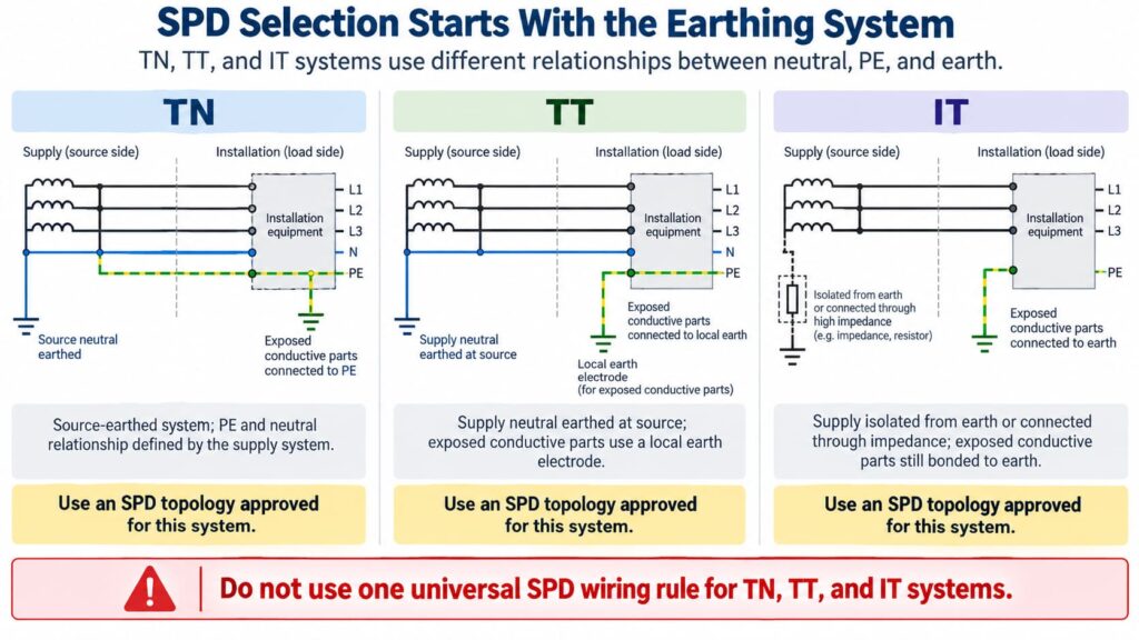
Dans un schéma TN-S, le neutre et le conducteur de protection (PE) sont des conducteurs séparés dans l'installation. Le parafoudre doit être sélectionné et raccordé en fonction de la configuration du système et des modes de protection concernés.
Dans les systèmes TN-C-S, le conducteur PEN en amont est divisé en conducteurs N et PE distincts en un point défini. Un parafoudre installé sur la partie TN-S doit être adapté à cette partie du système. Le schéma de raccordement exact doit respecter les instructions du produit et les exigences locales.
Do not create an extra neutral-to-earth link beside the SPD as an improvised “better ground.” Neutral/PE bonding is a system-design issue, not a field modification to improve SPD performance.
In a TT system, the installation’s exposed conductive parts are connected to a local earth electrode while the supply neutral has its own source earthing arrangement.
This affects SPD topology, protection modes, temporary overvoltage behavior, and coordination with protective devices. Depending on the design, manufacturers often provide specific TT-compatible SPD arrangements rather than treating a TN model as universally interchangeable.
The correct question is therefore not “Does TT have a ground rod?” but:
Is this SPD and its connection arrangement specifically suitable for the TT system at this installation point?
In an IT system, the supply may be isolated from earth or connected to earth through an impedance, while exposed conductive parts remain earthed according to the installation design.
This creates different voltage conditions, especially during a first insulation fault. An SPD used in an IT system must therefore be explicitly suitable for that system and for the possible continuous and temporary voltages it can experience.
Do not choose an SPD for an IT system solely because its Uc value appears high enough.
For AC SPDs, IEC 61643-11:2025 specifies performance and safety requirements for SPDs connected to AC low-voltage power systems. System selection and installation still require coordination with the actual network and installation rules. See the IEC 61643-11:2025 publication page.
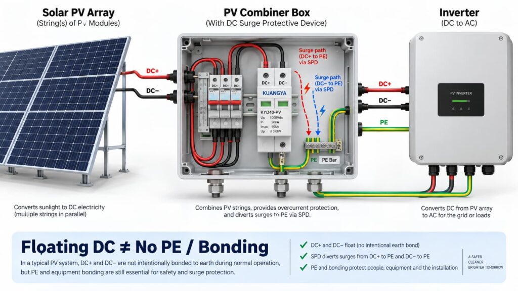
In solar PV systems, the question “can an SPD work without ground?” becomes even more complicated because the DC circuit may be intentionally floating.
Many PV DC circuits operate with neither DC+ nor DC− intentionally bonded directly to earth during normal operation. This is often described as a floating or unearthed DC array.
But that does pas mean the whole PV installation has no protective earth, bonding or surge path to PE.
A PV SPD may provide coordinated protection between:
Some PV SPDs use a Y-type internal circuit specifically intended for photovoltaic applications. The correct arrangement depends on the inverter topology, PV earthing arrangement, maximum PV voltage, insulation-monitoring concept and the manufacturer’s approved circuit.
This is why a floating PV system can still use a PE-connected SPD arrangement.
IEC 61643-31 applies to SPDs intended for the DC side of photovoltaic installations up to 1500 V DC and covers their performance characteristics, safety requirements, test methods and ratings. See the IEC 61643-31 publication page.
Before selecting a PV SPD, also verify Ucpv, In, Imax, Up and Iscpv. Our guide des spécifications des parafoudres CC explains what these markings mean and why the largest kA number is not enough.
Non.
A 2P or 3P description does not automatically tell you:
For the same reason, AC module count can also be misleading. If you are comparing neutral/PE arrangements, see our Comparaison des parafoudres 3+1 vs 4+0.
An SPD can be correctly selected and correctly connected to PE, yet still provide poorer installed protection because the connection conductors are too long.
The reason is conductor inductance.
During a fast-rising surge current, additional voltage develops across the SPD connecting conductors:
ΔU = L × di/dt
Où ?
This means the equipment does not necessarily see only the SPD’s datasheet voltage protection level Up. The installed voltage can also include voltage developed across the connection path.
Schneider Electric’s Electrical Installation Guide recommends keeping the total SPD connection length to the network and earth terminal block at no more than approximately 50 cm in the illustrated arrangement and explains the added inductive voltage created by longer conductors. See its SPD connection guidance.
The current consolidated IEC installation standard is IEC 60364-5-53:2019 + Amendment 1:2020 + Amendment 2:2024, which includes Clause 534 for surge protective devices. See the IEC 60364-5-53 consolidated publication page.
If you want a deeper explanation of why conductor length matters during a surge, read our guide on SPD distance from the inverter and connection lead length.
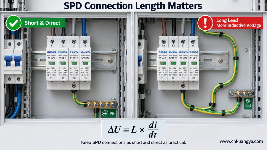
So when asking whether an SPD can work without ground, the quality and length of the PE connection are just as important as whether a protective-earth conductor is physically present.
Trying to reduce lead length by bypassing the approved panel bonding arrangement and connecting an SPD to a separate, isolated earth electrode can create a different problem: the installation may no longer be equipotentially bonded as required.
The correct objective is not “find the nearest piece of earth.”
C'est :
Connect the SPD to the manufacturer-specified PE/bonding point using the shortest practical, low-impedance path permitted by the system design.
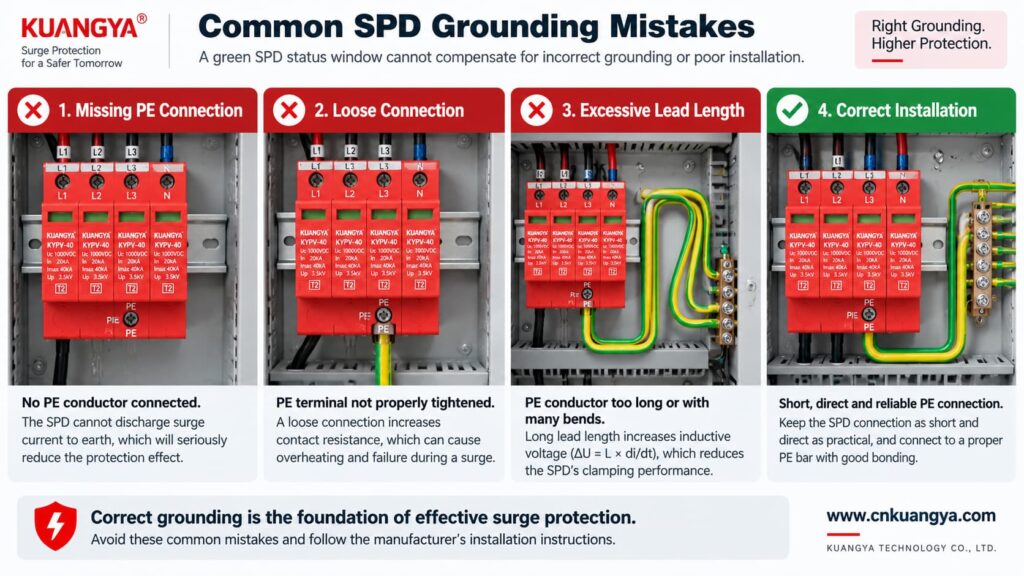
Poor grounding is not one single failure mode. The effect depends on what is actually wrong.
| Problème | Possible Effect | Ce qu'il faut vérifier |
|---|---|---|
| PE conductor missing | PE-dependent protection modes may not function as intended | Wiring diagram, PE continuity, bonding arrangement |
| Loose PE terminal | Unstable/high-impedance surge path, heating or arcing risk under fault conditions | Terminal condition and specified torque |
| Very long SPD connection | Higher installed residual voltage due to inductive voltage | Lead length and routing |
| Large conductor loop | Higher inductive coupling and loop impedance | Routing and loop area |
| Wrong TN/TT/IT SPD topology | Incorrect protection modes or unsuitable voltage stress | System earthing arrangement and manufacturer approval |
| Unbonded conductive systems | Dangerous transient potential differences may remain | Equipotential bonding of incoming services and installation |
| Green SPD indicator but external wiring fault | False confidence | Inspect the complete installation, not only the indicator |
Not by itself.
This is another important distinction.
A low measured earth-electrode resistance can be useful for the earthing system, but SPD performance during a fast transient also depends heavily on:
Therefore, a long conductor to an excellent earth electrode can still develop significant transient voltage during a steep surge current.
For surge protection, think in terms of impedance and equipotential bonding, not only DC or low-frequency resistance.
Can an SPD work without ground when it only protects L–N? It may limit the voltage between L and N if that is an approved protection mode of the device.
However, three cautions are essential.
If a surge raises both L and N relative to PE, an L–N element may see relatively little differential voltage even though the equipment is experiencing a large common-mode voltage relative to earth.
Electronic equipment can have chassis connections, signal cables, communication ports, antennas, shields or other conductive interfaces that create additional surge paths.
Do not intentionally leave a PE terminal disconnected on an SPD that is designed to use it. The correct wiring diagram is part of the product’s protection concept.
A backup fuse or circuit breaker does not replace grounding.
Likewise, grounding does not replace backup overcurrent protection where the SPD manufacturer requires it.
| Component / Function | Main Role |
|---|---|
| DOCUP | Limits transient overvoltage and diverts surge current through defined protection modes |
| PE / bonding system | Provides protective bonding and reference/discharge paths according to the installation design |
| Backup fuse or circuit breaker | Helps isolate fault current according to the SPD manufacturer’s coordination requirements |
| Earth electrode | Connects the installation earthing system to earth |
| Voltage protection relay / regulator | Addresses longer-duration abnormal voltage depending on device type |
If you are selecting upstream protection, see our practical guide: does an SPD need a backup fuse or circuit breaker?
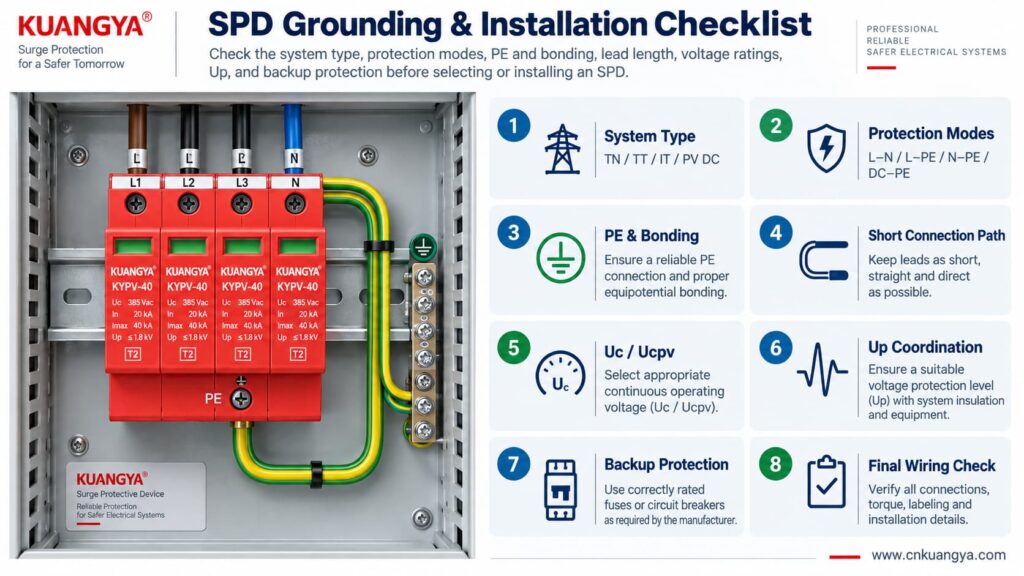
Use the following sequence as a design and inspection checklist. It is not a substitute for local electrical rules or the manufacturer’s instructions.
Confirm whether the circuit is:
Read the internal circuit or wiring diagram, not only the product front label.
Look for protection paths such as L–N, L–PE, N–PE, L1/L2/L3 relationships, DC+–PE and DC−–PE.
Connect only to the approved PE or bonding terminal shown by the manufacturer and installation design.
Avoid unnecessary conductor loops, coils and wide separation between surge-current paths.
For AC, confirm Uc and the applicable system voltage. For PV, confirm Ucpv against the maximum possible PV voltage, including cold-weather Voc where relevant.
Remember that installed protection depends on both the SPD’s Up and the voltage contribution of the connecting conductors.
Verify the manufacturer’s maximum backup fuse / circuit-breaker requirements and the prospective short-circuit conditions.
If an inverter already contains an SPD, do not assume external surge protection is unnecessary. Cable distance, system architecture and the location of the built-in SPD still matter. See our guide on solar inverter built-in SPD and external SPD requirements.
Before deciding whether an SPD can work without ground in a real installation, check the complete protection system rather than judging the SPD alone.
| Vérifier | Question | Pourquoi c'est important |
|---|---|---|
| Système | TN, TT, IT, AC or PV DC? | Determines compatible SPD topology |
| Les modes de protection | Which conductor pairs are protected? | Shows what voltage differences the SPD can limit |
| Raccordement PE | Is PE required and correctly connected? | Essential for PE-dependent protection modes |
| Bonding | Are relevant conductive systems equipotentially bonded? | Reduces dangerous transient potential differences |
| Lead length | Are SPD connections as short and direct as practical? | Reduces added inductive voltage |
| Tension | Is Uc / Ucpv correct? | Avoids continuous overvoltage stress |
| Protection level | Is Up coordinated with the equipment? | Determines residual voltage stress |
| Surge rating | Are In, Imax and/or Iimp suitable? | Matches expected surge duty |
| Short-circuit conditions | Are SCCR / Iscpv and backup protection suitable? | Important for safe failure and isolation |
| Manufacturer diagram | Does the installed wiring match the approved circuit? | Prevents topology mistakes |
For photovoltaic projects, KUANGYA provides Dispositifs de protection contre les surtensions en courant continu for different PV voltage classes and installation requirements. Final model selection should always be based on the actual PV voltage, earthing arrangement, protection mode, SPD type and system fault conditions.
Sometimes an individual protection mode such as L–N can operate without a direct PE connection. However, that does not mean the complete surge-protection system can ignore PE, earthing or equipotential bonding. Any SPD mode designed to operate between a live conductor and PE requires the intended PE connection.
When people ask “can an SPD work without ground?”, the answer depends on the SPD circuit rather than on one universal rule. Some devices or protection modes operate only between active conductors, while many power SPDs include PE-related protection modes. Follow the manufacturer’s circuit diagram and select the SPD for the actual TN, TT, IT or DC/PV system.
The SPD may still operate, but a long connection can add inductive voltage during a fast-rising surge current. This can increase the voltage that appears at the protected equipment. Short, direct connections are therefore an important part of SPD installation.
Do not improvise an isolated grounding path simply to make the SPD conductor shorter. The SPD should be connected to the approved PE/bonding point in accordance with the system design, manufacturer instructions and applicable electrical rules.
Not by itself. Surge performance also depends on high-frequency impedance, connection length, conductor routing, loop area, bonding and the SPD’s protection characteristics. A low earth-electrode resistance does not compensate for poor SPD wiring.
Yes. A PV DC system may have neither polarity intentionally grounded during normal operation while still using a properly designed SPD arrangement with protection paths to PE. Use a PV SPD approved for that topology and voltage.
No. A status indicator normally reports the condition of the SPD’s internal monitoring or disconnection mechanism. It does not verify external PE continuity, bonding, conductor length or correct earthing-system selection.
No. An SPD and the installation’s protective-earthing/bonding system perform different functions. A surge protective device should be considered part of a coordinated electrical protection system, not a replacement for protective earthing.
Grounding and bonding are fundamental parts of electrical safety and lightning/surge protection, but they do not perform the same voltage-limiting function as an SPD at equipment terminals. A complete design may require both, depending on the installation.
There is no single standard that answers every installation question. IEC 61643-11 covers AC low-voltage SPD product requirements, IEC 61643-31 covers PV DC SPD product requirements, and IEC 60364-5-53 includes installation requirements for low-voltage electrical installations, including Clause 534 for SPDs. Project-specific lightning-protection and national wiring requirements may also apply.
Un parafoudre peut-il fonctionner sans mise à la terre ? The answer cannot be reduced to a simple yes or no.
An SPD limits voltage across specific protection modes. A mode between active conductors, such as L–N, may operate without directly using PE. But any protection mode that depends on L–PE, N–PE, DC+–PE or DC−–PE requires the designed PE/bonding path.
More importantly, surge protection is a system function.
A correctly selected SPD can still perform poorly if:
For that reason, do not ask only:
“Does this SPD have a ground terminal?”
Ask instead:
“What voltage differences must be limited, what protection modes does this SPD provide, and how is the complete system bonded and earthed?”
That question leads to a much safer and more technically correct SPD selection.
Technical note: This article is intended for product selection and engineering education. Actual SPD installation must follow the device manufacturer’s wiring instructions, the applicable electrical installation standard, and local code requirements.

