温州市岳陽工業区 325000
勤務時間
月曜日~金曜日:午前7時~午後7時
週末午前10時~午後5時
温州市岳陽工業区 325000
勤務時間
月曜日~金曜日:午前7時~午後7時
週末午前10時~午後5時

SPDは接地なしで機能しますか?技術的に正しい回答は以下の通りです。 特定の保護モードでは直接的なPE経路なしでも動作することがありますが、それは接地やボンディングなしでサージ保護システム全体が正しく保護されていることを意味するわけではありません。.
サージ防護デバイス(SPD)は、単に「すべてのサージを大地に逃がす」わけではありません。保護モード間の電圧が動作領域を超えて上昇した際に導通状態になることで、規定された導体間の電圧を制限します。SPDの設計に応じて、これらの保護モードには線間・中性線間(L-N)、線間・保護接地間(L-PE)、中性線・保護接地間(N-PE)、またはDC+/DC-・PE間などが含まれます。.
これが、「接地されているか否か」という問いよりも複雑である理由です。真のエンジニアリング上の問いは以下の通りです。
解決しようとしている問題が接地ではなく、過渡サージと長時間過電圧との違いである場合は、まず以下をお読みください。 SPDは過電圧に対して保護しますか?. 接地によってSPDを電圧調整器や一般的な過電圧リレーに変えることはできません。.
SPDは接地なしで機能しますか? より適切な回答は以下の通りです: それは「接地」が何を意味するか、またどのSPD保護モードについて議論しているかによります。.
| 状況 | SPDはそれでも何らかの役割を果たせますか? | 主な懸念事項 |
|---|---|---|
| そのモードで直接的なPE接続がないL-N保護モード | 可能性がある | LとNの間の差動モード電圧のみが制限されている |
| PEが欠落している状態でのL-PEまたはN-PE保護モード | 意図した通りではない | 設計された保護経路が不完全または不適切である |
| 保護接地(PE)は存在するが、接続が長すぎる | SPDが動作する可能性がある | 追加の誘導電圧により、設置された保護レベルが上昇する可能性がある |
| TN/TT/IT接地システムに対して不適切なSPD | 正しい保護がなされていると想定してはならない | 保護モード、TOV(一時的過電圧)ストレス、および故障条件がシステムと一致していない可能性がある |
| 水上太陽光発電DCシステム | はい、適切に設計されたPV用SPD構成であれば可能です | “「フローティングDC」は、PE(保護接地)や等電位ボンディングを無視してよいという意味ではありません |
| 不適切なボンディング、または損傷したPE接続 | 保護機能が著しく損なわれる可能性があります | 導電性システム間に電位差が残留する可能性があります |
最も重要なルールは以下の通りです:
SPDに「接地が必要か」をモジュール数だけで判断しないでください。システムの接地方式と、SPDの実際の保護モードを確認してください。.
これが、2Pまたは3PのPV用SPDを外見だけで選定してはならない理由です。弊社の 2P対3P DC SPDガイド では、モジュール数、保護導体、PE接続、および内部保護経路がそれぞれ異なる概念であることを解説しています。.
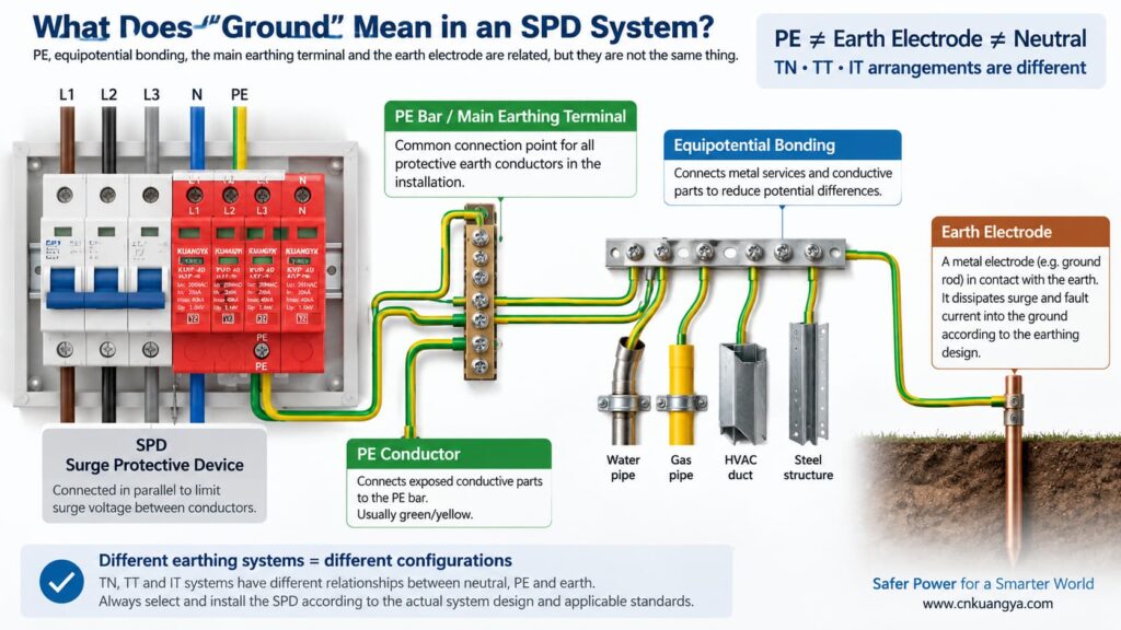
「SPDは接地なしで機能するか?」という問いに答える前に、まず電気設備において「接地」が実際に何を意味するのかを定義する必要があります。.
日常会話において、「接地」はいくつかの異なる事柄を指す場合があります。
PEとは、露出導電部と電気設備の保護ボンディングシステムを接続するために使用される保護導体です。多くの電源用SPDには、PEを基準とする保護モードが含まれています。.
これは、システム設計に従って保護導体が接続される、設置または配電盤内部のボンディングポイントです。.
接地極は、電気設備と大地との間に導電性の接続を提供します。これは接地システムの一部ですが、SPDと局所的なPEバーとの間の短いPE接続と混同してはなりません。.
ボンディングは、導電性部品および設備間の危険な電位差を低減します。サージ発生時、電位差を制御することは、サージ電流が「接地線を伝って」単一の経路を通ると考えることよりも重要である場合が多いです。“
中性線と接地線の関係は、接地システムによって異なります。TN、TT、およびITシステムでは中性線とPEの構成が同一ではないため、同じSPDトポロジーがどこでも適していると想定すべきではありません。.
ABBの実践的なSPDガイダンスでは、電源の中性線と機器の接地がどのように関連しているかに基づいて、TT、TN-C、TN-S、およびIT接地システムを区別しています。したがって、SPDの選定は、普遍的な「接地線」のルールに基づくのではなく、実際の電気システムと整合させる必要があります。.
一般的な電源用SPDは、回路に直列に接続されて通常の負荷電流を流すのではなく、回路に対して並列に接続されます。通常の状態では、そのサージ保護素子は高インピーダンス状態を維持します。保護モードの両端の電圧が十分に上昇すると、SPDは導通状態となり、サージ電流をその保護経路に分流させることで電圧を制限します。.
回路レベルの解説を先にご覧になりたい場合は、以下を参照してください。 なぜSPDは直列ではなく並列に接続されるのか.
「過電圧保護」というフレーズは、 “「サージ電流を大地に逃がす(divert surge current to ground)」” という表現は簡略化した説明としては有用ですが、誤解を招く可能性もあります。すべてのサージが接地棒に直接つながる1本の導体によって処理されるわけではありません。.
一般的な3つの保護モードを検討します:
| 保護モード | 制限される電圧 | このモードはPE(保護接地)を直接使用するか? |
|---|---|---|
| L–N | 中性線に対する相線 | その個別モードにおいて直接的なPE端子は不要 |
| L–PE | 保護接地に対する相線 | はい |
| N–PE | 保護接地に対する中性線 | はい |
| DC+–PE / DC−–PE | PEに対するPV導体 | はい |
これが本問題を理解するための鍵となります。.
L-N保護素子は、その素子が直接PEに接続されていなくても、線間と中性線間の差動電圧をクランプする可能性があります。しかし、設備がPEに対するコモンモードサージ電圧からの保護も必要とする場合、L-N経路のみでは、必要なPE関連の保護モードや等電位ボンディングシステムの代わりにはなりません。.
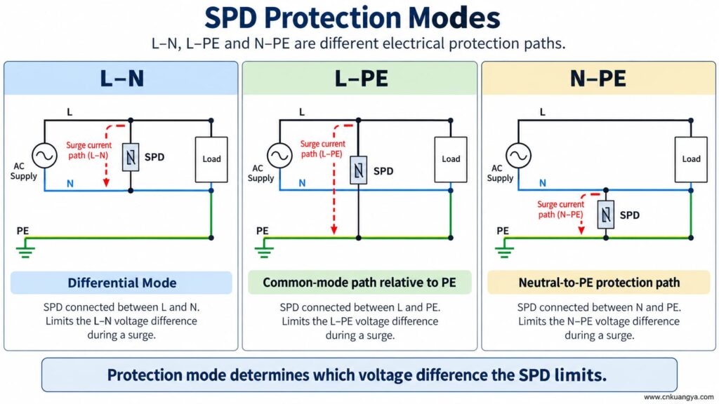
SPDは接地(アース)やPEなしで機能しますか? SPDが活線導体間のみの保護モードを有している場合、そのモードは導体間の電圧差に対して応答する可能性があります。しかし、PE依存の保護モードは、PE接続が欠如していると設計通りに機能しません。.
つまり、以下の2つの記述はどちらも真となり得ます。
したがって、SPDのステータスインジケーターが緑色を表示しているという理由だけで、PE接続を取り外したり、バイパスしたり、あるいは即興で変更したりしないでください。.
ステータスウィンドウは通常、監視対象の内部メカニズムの状態を示すものです。外部PE導体が存在すること、ボンディングシステムが適切であること、または接続長が許容範囲内であることを証明するものではありません。.
SPDがL-PE、N-PE、DC+-PE、またはDC--PEの保護経路で設計されており、PE接続が開放状態になった場合、それらのモードは意図された外部接続を失います。.
考えられる結果は以下の通りです:
保護導体の欠落は、SPDのトラブルシューティングの近道にはなりません。設置状況は、機器の取扱説明書および適用される電気規則に従い、有資格者によって点検および是正される必要があります。.
「SPDは接地なしで機能するか?」という問いへの答えは、TN、TT、およびITシステムにおける接地構成の違いによって異なります。.
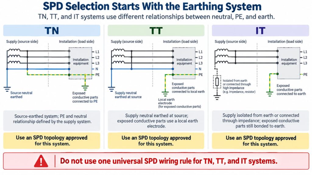
TN-S方式では、中性線と保護接地線(PE)は設備内で分離された導体となります。SPDは、関連するシステム構成および保護モードに合わせて選定・接続する必要があります。.
TN-C-Sシステムでは、上流側のPEN導体が所定の地点でNとPEに分離されます。TN-S部分に設置されるSPDは、そのシステム部分に適したものでなければなりません。正確な接続構成は、製品の取扱説明書および現地の要件に従う必要があります。.
Do not create an extra neutral-to-earth link beside the SPD as an improvised “better ground.” Neutral/PE bonding is a system-design issue, not a field modification to improve SPD performance.
In a TT system, the installation’s exposed conductive parts are connected to a local earth electrode while the supply neutral has its own source earthing arrangement.
This affects SPD topology, protection modes, temporary overvoltage behavior, and coordination with protective devices. Depending on the design, manufacturers often provide specific TT-compatible SPD arrangements rather than treating a TN model as universally interchangeable.
The correct question is therefore not “Does TT have a ground rod?” but:
Is this SPD and its connection arrangement specifically suitable for the TT system at this installation point?
In an IT system, the supply may be isolated from earth or connected to earth through an impedance, while exposed conductive parts remain earthed according to the installation design.
This creates different voltage conditions, especially during a first insulation fault. An SPD used in an IT system must therefore be explicitly suitable for that system and for the possible continuous and temporary voltages it can experience.
Do not choose an SPD for an IT system solely because its Uc value appears high enough.
For AC SPDs, IEC 61643-11:2025 specifies performance and safety requirements for SPDs connected to AC low-voltage power systems. System selection and installation still require coordination with the actual network and installation rules. See the IEC 61643-11:2025 publication page.
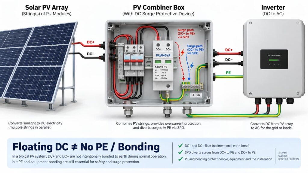
In solar PV systems, the question “can an SPD work without ground?” becomes even more complicated because the DC circuit may be intentionally floating.
Many PV DC circuits operate with neither DC+ nor DC− intentionally bonded directly to earth during normal operation. This is often described as a floating or unearthed DC array.
But that does ない mean the whole PV installation has no protective earth, bonding or surge path to PE.
A PV SPD may provide coordinated protection between:
Some PV SPDs use a Y-type internal circuit specifically intended for photovoltaic applications. The correct arrangement depends on the inverter topology, PV earthing arrangement, maximum PV voltage, insulation-monitoring concept and the manufacturer’s approved circuit.
This is why a floating PV system can still use a PE-connected SPD arrangement.
IEC 61643-31 applies to SPDs intended for the DC side of photovoltaic installations up to 1500 V DC and covers their performance characteristics, safety requirements, test methods and ratings. See the IEC 61643-31 publication page.
Before selecting a PV SPD, also verify Ucpv, In, Imax, Up and Iscpv. Our DC SPD仕様ガイドをご参照ください explains what these markings mean and why the largest kA number is not enough.
そうだ。.
A 2P or 3P description does not automatically tell you:
For the same reason, AC module count can also be misleading. If you are comparing neutral/PE arrangements, see our 3+1方式と4+0方式のSPD比較.
An SPD can be correctly selected and correctly connected to PE, yet still provide poorer installed protection because the connection conductors are too long.
The reason is conductor inductance.
During a fast-rising surge current, additional voltage develops across the SPD connecting conductors:
ΔU = L × di/dt
どこでだ:
This means the equipment does not necessarily see only the SPD’s datasheet voltage protection level Up. The installed voltage can also include voltage developed across the connection path.
Schneider Electric’s Electrical Installation Guide recommends keeping the total SPD connection length to the network and earth terminal block at no more than approximately 50 cm in the illustrated arrangement and explains the added inductive voltage created by longer conductors. See its SPD connection guidance.
The current consolidated IEC installation standard is IEC 60364-5-53:2019 + Amendment 1:2020 + Amendment 2:2024, which includes Clause 534 for surge protective devices. See the IEC 60364-5-53 consolidated publication page.
If you want a deeper explanation of why conductor length matters during a surge, read our guide on SPD distance from the inverter and connection lead length.
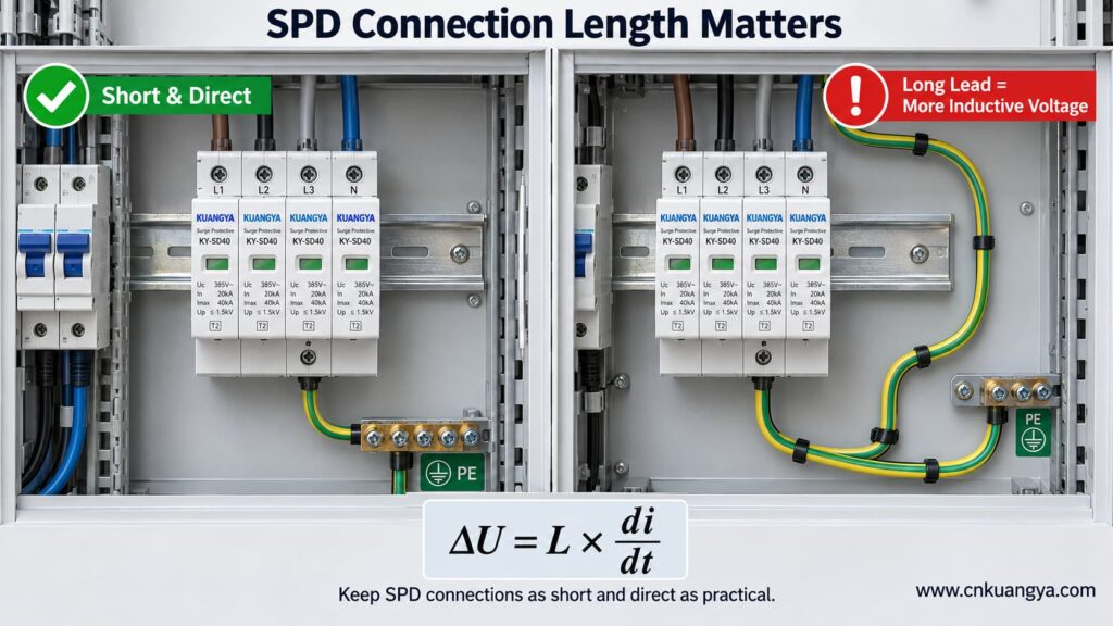
So when asking whether an SPD can work without ground, the quality and length of the PE connection are just as important as whether a protective-earth conductor is physically present.
Trying to reduce lead length by bypassing the approved panel bonding arrangement and connecting an SPD to a separate, isolated earth electrode can create a different problem: the installation may no longer be equipotentially bonded as required.
The correct objective is not “find the nearest piece of earth.”
正しくは次の通りです。
Connect the SPD to the manufacturer-specified PE/bonding point using the shortest practical, low-impedance path permitted by the system design.
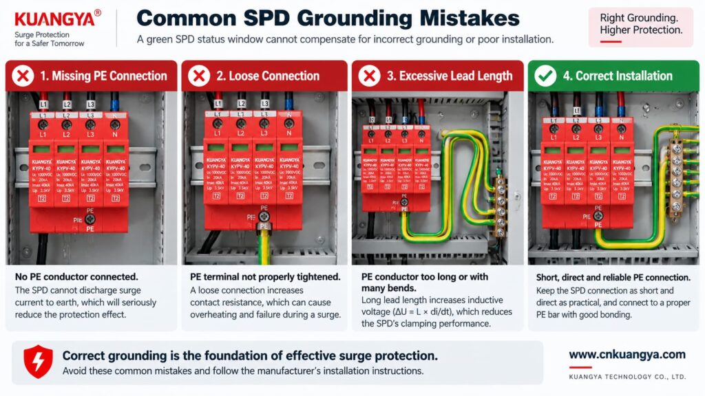
Poor grounding is not one single failure mode. The effect depends on what is actually wrong.
| 問題 | Possible Effect | 何をチェックすべきか |
|---|---|---|
| PE conductor missing | PE-dependent protection modes may not function as intended | Wiring diagram, PE continuity, bonding arrangement |
| Loose PE terminal | Unstable/high-impedance surge path, heating or arcing risk under fault conditions | Terminal condition and specified torque |
| Very long SPD connection | Higher installed residual voltage due to inductive voltage | Lead length and routing |
| Large conductor loop | Higher inductive coupling and loop impedance | Routing and loop area |
| Wrong TN/TT/IT SPD topology | Incorrect protection modes or unsuitable voltage stress | System earthing arrangement and manufacturer approval |
| Unbonded conductive systems | Dangerous transient potential differences may remain | Equipotential bonding of incoming services and installation |
| Green SPD indicator but external wiring fault | False confidence | Inspect the complete installation, not only the indicator |
Not by itself.
This is another important distinction.
A low measured earth-electrode resistance can be useful for the earthing system, but SPD performance during a fast transient also depends heavily on:
Therefore, a long conductor to an excellent earth electrode can still develop significant transient voltage during a steep surge current.
For surge protection, think in terms of impedance and equipotential bonding, not only DC or low-frequency resistance.
Can an SPD work without ground when it only protects L–N? It may limit the voltage between L and N if that is an approved protection mode of the device.
However, three cautions are essential.
If a surge raises both L and N relative to PE, an L–N element may see relatively little differential voltage even though the equipment is experiencing a large common-mode voltage relative to earth.
Electronic equipment can have chassis connections, signal cables, communication ports, antennas, shields or other conductive interfaces that create additional surge paths.
Do not intentionally leave a PE terminal disconnected on an SPD that is designed to use it. The correct wiring diagram is part of the product’s protection concept.
A backup fuse or circuit breaker does not replace grounding.
Likewise, grounding does not replace backup overcurrent protection where the SPD manufacturer requires it.
| Component / Function | Main Role |
|---|---|
| SPD | Limits transient overvoltage and diverts surge current through defined protection modes |
| PE / bonding system | Provides protective bonding and reference/discharge paths according to the installation design |
| Backup fuse or circuit breaker | Helps isolate fault current according to the SPD manufacturer’s coordination requirements |
| Earth electrode | Connects the installation earthing system to earth |
| Voltage protection relay / regulator | Addresses longer-duration abnormal voltage depending on device type |
If you are selecting upstream protection, see our practical guide: does an SPD need a backup fuse or circuit breaker?
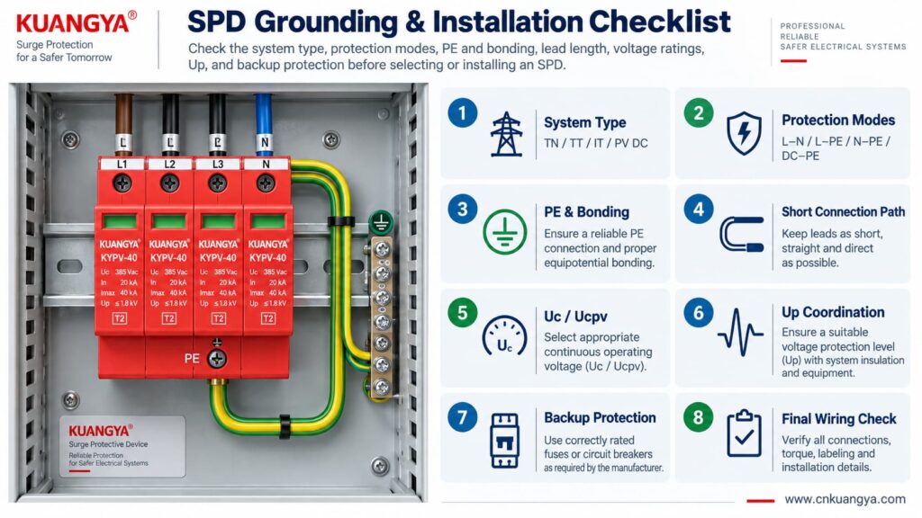
Use the following sequence as a design and inspection checklist. It is not a substitute for local electrical rules or the manufacturer’s instructions.
Confirm whether the circuit is:
Read the internal circuit or wiring diagram, not only the product front label.
Look for protection paths such as L–N, L–PE, N–PE, L1/L2/L3 relationships, DC+–PE and DC−–PE.
Connect only to the approved PE or bonding terminal shown by the manufacturer and installation design.
Avoid unnecessary conductor loops, coils and wide separation between surge-current paths.
For AC, confirm Uc and the applicable system voltage. For PV, confirm Ucpv against the maximum possible PV voltage, including cold-weather Voc where relevant.
Remember that installed protection depends on both the SPD’s Up and the voltage contribution of the connecting conductors.
Verify the manufacturer’s maximum backup fuse / circuit-breaker requirements and the prospective short-circuit conditions.
If an inverter already contains an SPD, do not assume external surge protection is unnecessary. Cable distance, system architecture and the location of the built-in SPD still matter. See our guide on solar inverter built-in SPD and external SPD requirements.
Before deciding whether an SPD can work without ground in a real installation, check the complete protection system rather than judging the SPD alone.
| チェック | 質問 | なぜ重要なのか |
|---|---|---|
| システム | TN, TT, IT, AC or PV DC? | Determines compatible SPD topology |
| 保護モード | Which conductor pairs are protected? | Shows what voltage differences the SPD can limit |
| PE接続 | Is PE required and correctly connected? | Essential for PE-dependent protection modes |
| Bonding | Are relevant conductive systems equipotentially bonded? | Reduces dangerous transient potential differences |
| Lead length | Are SPD connections as short and direct as practical? | Reduces added inductive voltage |
| 電圧 | Is Uc / Ucpv correct? | Avoids continuous overvoltage stress |
| Protection level | Is Up coordinated with the equipment? | Determines residual voltage stress |
| Surge rating | Are In, Imax and/or Iimp suitable? | Matches expected surge duty |
| Short-circuit conditions | Are SCCR / Iscpv and backup protection suitable? | Important for safe failure and isolation |
| Manufacturer diagram | Does the installed wiring match the approved circuit? | Prevents topology mistakes |
For photovoltaic projects, KUANGYA provides 直流サージ保護装置 for different PV voltage classes and installation requirements. Final model selection should always be based on the actual PV voltage, earthing arrangement, protection mode, SPD type and system fault conditions.
Sometimes an individual protection mode such as L–N can operate without a direct PE connection. However, that does not mean the complete surge-protection system can ignore PE, earthing or equipotential bonding. Any SPD mode designed to operate between a live conductor and PE requires the intended PE connection.
When people ask “can an SPD work without ground?”, the answer depends on the SPD circuit rather than on one universal rule. Some devices or protection modes operate only between active conductors, while many power SPDs include PE-related protection modes. Follow the manufacturer’s circuit diagram and select the SPD for the actual TN, TT, IT or DC/PV system.
The SPD may still operate, but a long connection can add inductive voltage during a fast-rising surge current. This can increase the voltage that appears at the protected equipment. Short, direct connections are therefore an important part of SPD installation.
Do not improvise an isolated grounding path simply to make the SPD conductor shorter. The SPD should be connected to the approved PE/bonding point in accordance with the system design, manufacturer instructions and applicable electrical rules.
Not by itself. Surge performance also depends on high-frequency impedance, connection length, conductor routing, loop area, bonding and the SPD’s protection characteristics. A low earth-electrode resistance does not compensate for poor SPD wiring.
Yes. A PV DC system may have neither polarity intentionally grounded during normal operation while still using a properly designed SPD arrangement with protection paths to PE. Use a PV SPD approved for that topology and voltage.
No. A status indicator normally reports the condition of the SPD’s internal monitoring or disconnection mechanism. It does not verify external PE continuity, bonding, conductor length or correct earthing-system selection.
No. An SPD and the installation’s protective-earthing/bonding system perform different functions. A surge protective device should be considered part of a coordinated electrical protection system, not a replacement for protective earthing.
Grounding and bonding are fundamental parts of electrical safety and lightning/surge protection, but they do not perform the same voltage-limiting function as an SPD at equipment terminals. A complete design may require both, depending on the installation.
There is no single standard that answers every installation question. IEC 61643-11 covers AC low-voltage SPD product requirements, IEC 61643-31 covers PV DC SPD product requirements, and IEC 60364-5-53 includes installation requirements for low-voltage electrical installations, including Clause 534 for SPDs. Project-specific lightning-protection and national wiring requirements may also apply.
SPDは接地なしで機能しますか? The answer cannot be reduced to a simple yes or no.
An SPD limits voltage across specific protection modes. A mode between active conductors, such as L–N, may operate without directly using PE. But any protection mode that depends on L–PE, N–PE, DC+–PE or DC−–PE requires the designed PE/bonding path.
More importantly, surge protection is a system function.
A correctly selected SPD can still perform poorly if:
For that reason, do not ask only:
“Does this SPD have a ground terminal?”
Ask instead:
“What voltage differences must be limited, what protection modes does this SPD provide, and how is the complete system bonded and earthed?”
That question leads to a much safer and more technically correct SPD selection.
Technical note: This article is intended for product selection and engineering education. Actual SPD installation must follow the device manufacturer’s wiring instructions, the applicable electrical installation standard, and local code requirements.

