Промышленная зона Вэньян Юэцин Вэньчжоу 325000
Рабочие часы
Понедельник - пятница: 7AM - 7PM
Выходные: 10AM - 5PM
Промышленная зона Вэньян Юэцин Вэньчжоу 325000
Рабочие часы
Понедельник - пятница: 7AM - 7PM
Выходные: 10AM - 5PM

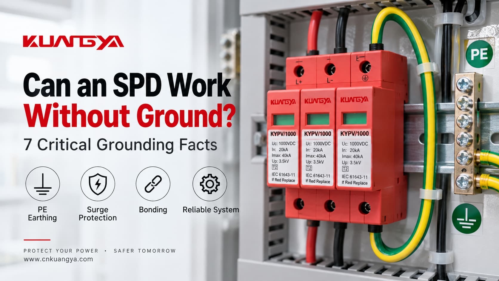
Может ли УЗИП работать без заземления? Технически правильный ответ: иногда определенный режим защиты может функционировать без прямого пути к PE, но это не означает, что вся система защиты от перенапряжений корректно защищена без заземления или уравнивания потенциалов.
Устройство защиты от перенапряжений не просто “отправляет каждый скачок напряжения в землю”. Оно ограничивает напряжение между заданными проводниками, становясь проводящим, когда напряжение в режиме защиты превышает рабочий диапазон. В зависимости от конструкции УЗИП, эти режимы защиты могут включать: фаза-нейтраль (L–N), фаза-защитное заземление (L–PE), нейтраль-защитное заземление (N–PE) или DC+/DC− относительно PE.
Вот почему этот вопрос сложнее, чем просто “заземлено или не заземлено”. Настоящие инженерные вопросы звучат так:
Если проблема, которую вы пытаетесь решить, заключается не в заземлении, а в разнице между импульсным перенапряжением и проблемой длительного повышения напряжения, сначала прочитайте защищает ли УЗИП от перенапряжения. Заземление не может превратить УЗИП в регулятор напряжения или реле контроля напряжения общего назначения.
Может ли УЗИП работать без заземления? Более точный ответ: это зависит от того, что подразумевается под “заземлением” и какой режим защиты УЗИП рассматривается.
| Ситуация | Может ли УЗИП в таком случае выполнять хоть какую-то функцию? | Основная проблема |
|---|---|---|
| Режим защиты L–N при отсутствии прямого подключения к PE в этом режиме | Возможно, да | Ограничивается только дифференциальное напряжение между фазой (L) и нейтралью (N) |
| Режим защиты L–PE или N–PE при отсутствии PE | Не соответствует назначению | Проектируемый путь защиты неполный или некорректный |
| Защитное заземление (PE) присутствует, но соединение чрезмерно длинное | УЗИП может продолжать функционировать | Дополнительное индуктивное напряжение может повысить уровень установленной защиты |
| Некорректный выбор УЗИП для систем заземления TN/TT/IT | Не следует полагаться на правильность защиты | Режимы защиты, воздействие временных перенапряжений (TOV) и условия неисправности могут не соответствовать системе |
| Плавучая фотоэлектрическая система постоянного тока | Да, при условии правильно спроектированной схемы УЗИП для фотоэлектрических систем | “Плавающий постоянный ток” не означает, что можно игнорировать защитное заземление (PE) и уравнивание потенциалов |
| Отсутствие эффективного соединения / поврежденное соединение PE | Защита может быть серьезно нарушена | Между токопроводящими системами может сохраняться разность потенциалов |
Самое важное правило:
Не принимайте решение о том, “нужно ли заземление” для УЗИП, основываясь только на количестве модулей. Определите систему заземления и фактические режимы защиты УЗИП.
По этой же причине 2P или 3P УЗИП для фотоэлектрических систем не следует выбирать только по внешнему виду. Наше Руководство по сравнению 2P и 3P УЗИП постоянного тока объясняет, почему количество модулей, защищаемые проводники, подключение к PE и внутренние пути защиты являются разными понятиями.
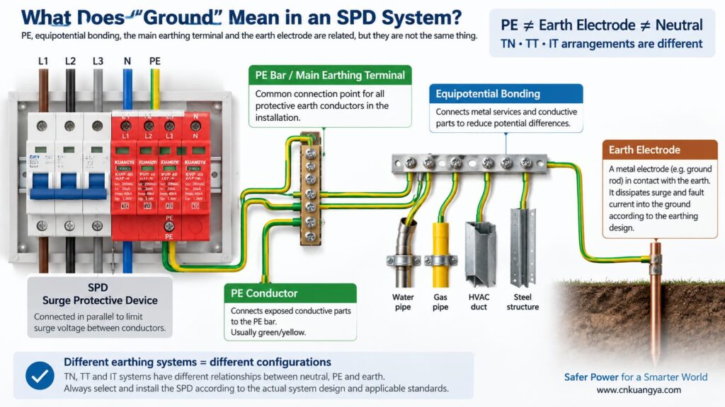
Прежде чем ответить на вопрос “может ли УЗИП работать без заземления?”, нам сначала нужно определить, что на самом деле означает “заземление” в электроустановке.
В повседневной речи под “заземлением” могут подразумеваться несколько разных вещей:
PE — это защитный проводник, используемый для соединения открытых проводящих частей с системой уравнивания потенциалов электроустановки. Многие устройства защиты от импульсных перенапряжений (УЗИП) включают режимы защиты, привязанные к PE.
Это точка уравнивания потенциалов внутри электроустановки или распределительного щита, к которой согласно проекту системы подключаются защитные проводники.
Заземлитель обеспечивает проводящее соединение между электроустановкой и землей. Он является частью системы заземления, однако его не следует путать с коротким соединением PE между устройством защиты от импульсных перенапряжений (УЗИП) и локальной шиной PE.
Уравнивание потенциалов снижает опасную разность напряжений между токопроводящими частями и инженерными коммуникациями. Во время скачка напряжения контроль разности потенциалов зачастую важнее, чем представление импульсного тока как простого пути “вниз по проводу заземления”.”
Взаимосвязь между нейтралью и землей зависит от системы заземления. В системах TN, TT и IT используются разные схемы подключения нейтрали и PE, что является одной из причин, почему нельзя считать одну и ту же топологию УЗИП подходящей для всех случаев.
Практическое руководство ABB по УЗИП различает системы заземления TT, TN-C, TN-S и IT в зависимости от того, как связаны нейтраль источника питания и заземление оборудования. Поэтому выбор УЗИП должен быть согласован с конкретной электрической системой, а не основываться на универсальном правиле “провода заземления”.
Типовое устройство защиты от импульсных перенапряжений (УЗИП) подключается параллельно цепи, а не последовательно с нагрузкой. В нормальных условиях элементы защиты находятся в высокоомном состоянии. Когда напряжение в режиме защиты достигает порогового значения, УЗИП переходит в проводящее состояние и ограничивает напряжение, отводя импульсный ток через путь защиты.
Если вы хотите сначала получить объяснение на уровне электрической цепи, см. почему УЗИП подключается параллельно, а не последовательно.
Фраза “отвод импульсного тока на землю” является полезным упрощенным объяснением, но может привести к недопониманию. Не каждый импульс тока отводится по одному проводнику непосредственно на заземлитель.
Рассмотрим три распространенных режима защиты:
| Режим защиты | Ограничиваемое напряжение | Использует ли этот режим непосредственно защитное заземление (PE)? |
|---|---|---|
| L–N | Фаза относительно нейтрали | Для данного конкретного режима отдельная клемма защитного заземления (PE) не требуется |
| L–PE | Фаза относительно защитного заземления | Да |
| N–PE | Нейтраль относительно защитного заземления | Да |
| DC+–PE / DC−–PE | Проводники фотоэлектрической системы относительно защитного заземления (PE) | Да |
Это ключ к пониманию вопроса.
Защитный элемент L–N может ограничивать дифференциальное напряжение между фазным и нейтральным проводниками, даже если этот конкретный элемент не подключен напрямую к PE. Однако, если установка также требует защиты от синфазного импульсного перенапряжения относительно PE, одного пути L–N недостаточно для замены требуемых режимов защиты, связанных с PE, и системы уравнивания потенциалов.
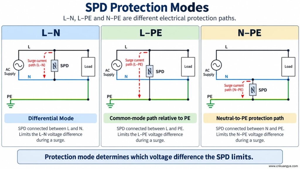
Может ли УЗИП работать без заземления или PE? Если УЗИП имеет только режим защиты между активными проводниками, этот режим может реагировать на разность потенциалов между ними. Но режим защиты, зависящий от PE, не сможет функционировать должным образом при отсутствии подключения к PE.
Это означает, что оба утверждения могут быть верными:
Поэтому никогда не удаляйте, не обходите и не импровизируйте с подключением PE только потому, что УЗИП по-прежнему показывает зеленый индикатор состояния.
Окно состояния обычно отображает работоспособность контролируемого внутреннего механизма. Оно не подтверждает наличие внешнего проводника PE, правильность системы уравнивания потенциалов или допустимую длину подключения.
Если УЗИП спроектировано с путями защиты L–PE, N–PE, DC+–PE или DC−–PE, а соединение с PE становится разомкнутым, эти режимы теряют предусмотренное внешнее подключение.
Возможные последствия включают:
Отсутствие защитного проводника не является способом устранения неисправностей УЗИП. Установка должна быть проверена и исправлена квалифицированным специалистом в соответствии с инструкциями к оборудованию и применимыми электротехническими нормами.
Ответ на вопрос “может ли УЗИП работать без заземления?” меняется, поскольку архитектура заземления различается в системах TN, TT и IT.
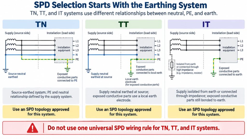
В схеме TN-S нейтральный проводник и PE-проводник являются раздельными в электроустановке. УЗИП должно быть выбрано и подключено в соответствии с конфигурацией системы и режимами защиты.
В системах TN-C-S PEN-проводник со стороны источника питания разделяется на отдельные N и PE в определенной точке. Устройство защиты от импульсных перенапряжений (УЗИП), установленное в части системы TN-S, должно соответствовать требованиям для данной части системы. Точная схема подключения должна соответствовать инструкциям к изделию и местным нормативным требованиям.
Не создавайте дополнительное соединение между нейтралью и заземлением рядом с УЗИП в качестве импровизированного “улучшенного заземления”. Соединение нейтрали и PE является вопросом проектирования системы, а не полевой модификацией для повышения эффективности работы УЗИП.
In a TT system, the installation’s exposed conductive parts are connected to a local earth electrode while the supply neutral has its own source earthing arrangement.
This affects SPD topology, protection modes, temporary overvoltage behavior, and coordination with protective devices. Depending on the design, manufacturers often provide specific TT-compatible SPD arrangements rather than treating a TN model as universally interchangeable.
The correct question is therefore not “Does TT have a ground rod?” but:
Is this SPD and its connection arrangement specifically suitable for the TT system at this installation point?
In an IT system, the supply may be isolated from earth or connected to earth through an impedance, while exposed conductive parts remain earthed according to the installation design.
This creates different voltage conditions, especially during a first insulation fault. An SPD used in an IT system must therefore be explicitly suitable for that system and for the possible continuous and temporary voltages it can experience.
Do not choose an SPD for an IT system solely because its Uc value appears high enough.
For AC SPDs, IEC 61643-11:2025 specifies performance and safety requirements for SPDs connected to AC low-voltage power systems. System selection and installation still require coordination with the actual network and installation rules. See the IEC 61643-11:2025 publication page.
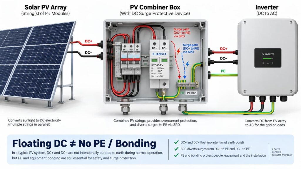
In solar PV systems, the question “can an SPD work without ground?” becomes even more complicated because the DC circuit may be intentionally floating.
Many PV DC circuits operate with neither DC+ nor DC− intentionally bonded directly to earth during normal operation. This is often described as a floating or unearthed DC array.
But that does не mean the whole PV installation has no protective earth, bonding or surge path to PE.
A PV SPD may provide coordinated protection between:
Some PV SPDs use a Y-type internal circuit specifically intended for photovoltaic applications. The correct arrangement depends on the inverter topology, PV earthing arrangement, maximum PV voltage, insulation-monitoring concept and the manufacturer’s approved circuit.
This is why a floating PV system can still use a PE-connected SPD arrangement.
IEC 61643-31 applies to SPDs intended for the DC side of photovoltaic installations up to 1500 V DC and covers their performance characteristics, safety requirements, test methods and ratings. See the IEC 61643-31 publication page.
Before selecting a PV SPD, also verify Ucpv, In, Imax, Up and Iscpv. Our руководство по техническим характеристикам УЗИП постоянного тока explains what these markings mean and why the largest kA number is not enough.
Нет.
A 2P or 3P description does not automatically tell you:
For the same reason, AC module count can also be misleading. If you are comparing neutral/PE arrangements, see our Сравнение УЗИП 3+1 и 4+0.
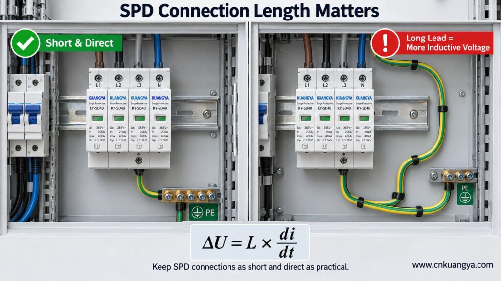
An SPD can be correctly selected and correctly connected to PE, yet still provide poorer installed protection because the connection conductors are too long.
The reason is conductor inductance.
During a fast-rising surge current, additional voltage develops across the SPD connecting conductors:
ΔU = L × di/dt
Где:
This means the equipment does not necessarily see only the SPD’s datasheet voltage protection level Up. The installed voltage can also include voltage developed across the connection path.
Schneider Electric’s Electrical Installation Guide recommends keeping the total SPD connection length to the network and earth terminal block at no more than approximately 50 cm in the illustrated arrangement and explains the added inductive voltage created by longer conductors. See its SPD connection guidance.
The current consolidated IEC installation standard is IEC 60364-5-53:2019 + Amendment 1:2020 + Amendment 2:2024, which includes Clause 534 for surge protective devices. See the IEC 60364-5-53 consolidated publication page.
If you want a deeper explanation of why conductor length matters during a surge, read our guide on SPD distance from the inverter and connection lead length.
So when asking whether an SPD can work without ground, the quality and length of the PE connection are just as important as whether a protective-earth conductor is physically present.
Trying to reduce lead length by bypassing the approved panel bonding arrangement and connecting an SPD to a separate, isolated earth electrode can create a different problem: the installation may no longer be equipotentially bonded as required.
The correct objective is not “find the nearest piece of earth.”
А в том:
Connect the SPD to the manufacturer-specified PE/bonding point using the shortest practical, low-impedance path permitted by the system design.
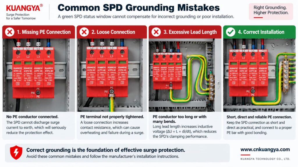
Poor grounding is not one single failure mode. The effect depends on what is actually wrong.
| Проблема | Possible Effect | Что проверить |
|---|---|---|
| PE conductor missing | PE-dependent protection modes may not function as intended | Wiring diagram, PE continuity, bonding arrangement |
| Loose PE terminal | Unstable/high-impedance surge path, heating or arcing risk under fault conditions | Terminal condition and specified torque |
| Very long SPD connection | Higher installed residual voltage due to inductive voltage | Lead length and routing |
| Large conductor loop | Higher inductive coupling and loop impedance | Routing and loop area |
| Wrong TN/TT/IT SPD topology | Incorrect protection modes or unsuitable voltage stress | System earthing arrangement and manufacturer approval |
| Unbonded conductive systems | Dangerous transient potential differences may remain | Equipotential bonding of incoming services and installation |
| Green SPD indicator but external wiring fault | False confidence | Inspect the complete installation, not only the indicator |
Not by itself.
This is another important distinction.
A low measured earth-electrode resistance can be useful for the earthing system, but SPD performance during a fast transient also depends heavily on:
Therefore, a long conductor to an excellent earth electrode can still develop significant transient voltage during a steep surge current.
For surge protection, think in terms of impedance and equipotential bonding, not only DC or low-frequency resistance.
Can an SPD work without ground when it only protects L–N? It may limit the voltage between L and N if that is an approved protection mode of the device.
However, three cautions are essential.
If a surge raises both L and N relative to PE, an L–N element may see relatively little differential voltage even though the equipment is experiencing a large common-mode voltage relative to earth.
Electronic equipment can have chassis connections, signal cables, communication ports, antennas, shields or other conductive interfaces that create additional surge paths.
Do not intentionally leave a PE terminal disconnected on an SPD that is designed to use it. The correct wiring diagram is part of the product’s protection concept.
A backup fuse or circuit breaker does not replace grounding.
Likewise, grounding does not replace backup overcurrent protection where the SPD manufacturer requires it.
| Component / Function | Main Role |
|---|---|
| СПД | Limits transient overvoltage and diverts surge current through defined protection modes |
| PE / bonding system | Provides protective bonding and reference/discharge paths according to the installation design |
| Backup fuse or circuit breaker | Helps isolate fault current according to the SPD manufacturer’s coordination requirements |
| Earth electrode | Connects the installation earthing system to earth |
| Voltage protection relay / regulator | Addresses longer-duration abnormal voltage depending on device type |
If you are selecting upstream protection, see our practical guide: does an SPD need a backup fuse or circuit breaker?
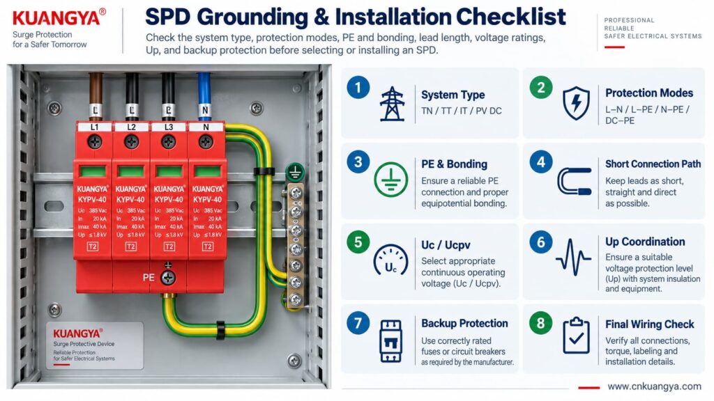
Use the following sequence as a design and inspection checklist. It is not a substitute for local electrical rules or the manufacturer’s instructions.
Confirm whether the circuit is:
Read the internal circuit or wiring diagram, not only the product front label.
Look for protection paths such as L–N, L–PE, N–PE, L1/L2/L3 relationships, DC+–PE and DC−–PE.
Connect only to the approved PE or bonding terminal shown by the manufacturer and installation design.
Avoid unnecessary conductor loops, coils and wide separation between surge-current paths.
For AC, confirm Uc and the applicable system voltage. For PV, confirm Ucpv against the maximum possible PV voltage, including cold-weather Voc where relevant.
Remember that installed protection depends on both the SPD’s Up and the voltage contribution of the connecting conductors.
Verify the manufacturer’s maximum backup fuse / circuit-breaker requirements and the prospective short-circuit conditions.
If an inverter already contains an SPD, do not assume external surge protection is unnecessary. Cable distance, system architecture and the location of the built-in SPD still matter. See our guide on solar inverter built-in SPD and external SPD requirements.
Before deciding whether an SPD can work without ground in a real installation, check the complete protection system rather than judging the SPD alone.
| Проверьте | Вопрос | Почему это важно |
|---|---|---|
| Система | TN, TT, IT, AC or PV DC? | Determines compatible SPD topology |
| Режимы защиты | Which conductor pairs are protected? | Shows what voltage differences the SPD can limit |
| Подключение защитного заземления (PE) | Is PE required and correctly connected? | Essential for PE-dependent protection modes |
| Bonding | Are relevant conductive systems equipotentially bonded? | Reduces dangerous transient potential differences |
| Lead length | Are SPD connections as short and direct as practical? | Reduces added inductive voltage |
| Напряжение | Is Uc / Ucpv correct? | Avoids continuous overvoltage stress |
| Protection level | Is Up coordinated with the equipment? | Determines residual voltage stress |
| Surge rating | Are In, Imax and/or Iimp suitable? | Matches expected surge duty |
| Short-circuit conditions | Are SCCR / Iscpv and backup protection suitable? | Important for safe failure and isolation |
| Manufacturer diagram | Does the installed wiring match the approved circuit? | Prevents topology mistakes |
For photovoltaic projects, KUANGYA provides Устройства защиты от перенапряжения постоянного тока for different PV voltage classes and installation requirements. Final model selection should always be based on the actual PV voltage, earthing arrangement, protection mode, SPD type and system fault conditions.
Sometimes an individual protection mode such as L–N can operate without a direct PE connection. However, that does not mean the complete surge-protection system can ignore PE, earthing or equipotential bonding. Any SPD mode designed to operate between a live conductor and PE requires the intended PE connection.
When people ask “can an SPD work without ground?”, the answer depends on the SPD circuit rather than on one universal rule. Some devices or protection modes operate only between active conductors, while many power SPDs include PE-related protection modes. Follow the manufacturer’s circuit diagram and select the SPD for the actual TN, TT, IT or DC/PV system.
The SPD may still operate, but a long connection can add inductive voltage during a fast-rising surge current. This can increase the voltage that appears at the protected equipment. Short, direct connections are therefore an important part of SPD installation.
Do not improvise an isolated grounding path simply to make the SPD conductor shorter. The SPD should be connected to the approved PE/bonding point in accordance with the system design, manufacturer instructions and applicable electrical rules.
Not by itself. Surge performance also depends on high-frequency impedance, connection length, conductor routing, loop area, bonding and the SPD’s protection characteristics. A low earth-electrode resistance does not compensate for poor SPD wiring.
Yes. A PV DC system may have neither polarity intentionally grounded during normal operation while still using a properly designed SPD arrangement with protection paths to PE. Use a PV SPD approved for that topology and voltage.
No. A status indicator normally reports the condition of the SPD’s internal monitoring or disconnection mechanism. It does not verify external PE continuity, bonding, conductor length or correct earthing-system selection.
No. An SPD and the installation’s protective-earthing/bonding system perform different functions. A surge protective device should be considered part of a coordinated electrical protection system, not a replacement for protective earthing.
Grounding and bonding are fundamental parts of electrical safety and lightning/surge protection, but they do not perform the same voltage-limiting function as an SPD at equipment terminals. A complete design may require both, depending on the installation.
There is no single standard that answers every installation question. IEC 61643-11 covers AC low-voltage SPD product requirements, IEC 61643-31 covers PV DC SPD product requirements, and IEC 60364-5-53 includes installation requirements for low-voltage electrical installations, including Clause 534 for SPDs. Project-specific lightning-protection and national wiring requirements may also apply.
Может ли УЗИП работать без заземления? The answer cannot be reduced to a simple yes or no.
An SPD limits voltage across specific protection modes. A mode between active conductors, such as L–N, may operate without directly using PE. But any protection mode that depends on L–PE, N–PE, DC+–PE or DC−–PE requires the designed PE/bonding path.
More importantly, surge protection is a system function.
A correctly selected SPD can still perform poorly if:
For that reason, do not ask only:
“Does this SPD have a ground terminal?”
Ask instead:
“What voltage differences must be limited, what protection modes does this SPD provide, and how is the complete system bonded and earthed?”
That question leads to a much safer and more technically correct SPD selection.
Technical note: This article is intended for product selection and engineering education. Actual SPD installation must follow the device manufacturer’s wiring instructions, the applicable electrical installation standard, and local code requirements.

