Zona industriale di WengYang Yueqing Wenzhou 325000
Orario di lavoro
Da lunedì a venerdì: dalle 7.00 alle 19.00
Fine settimana: 10.00 - 17.00
Zona industriale di WengYang Yueqing Wenzhou 325000
Orario di lavoro
Da lunedì a venerdì: dalle 7.00 alle 19.00
Fine settimana: 10.00 - 17.00

Un SPD può funzionare senza messa a terra? La risposta tecnicamente corretta è: a volte una specifica modalità di protezione può comunque operare senza un percorso PE diretto, ma ciò non significa che l'intero sistema di protezione dalle sovratensioni sia protetto correttamente senza messa a terra o collegamento equipotenziale.
Un dispositivo di protezione contro le sovratensioni (SPD) non si limita a “inviare ogni sovratensione nel terreno”. Esso limita la tensione tra i conduttori definiti diventando conduttivo quando la tensione attraverso una modalità di protezione supera la sua regione operativa. A seconda del design dell'SPD, tali modalità di protezione possono includere fase-neutro (L–N), fase-terra di protezione (L–PE), neutro-terra di protezione (N–PE) o DC+/DC− verso PE.
Ecco perché la questione è più complessa di un semplice “con o senza messa a terra”. Le vere domande ingegneristiche sono:
Se il problema che si sta cercando di risolvere non è la messa a terra, ma la differenza tra un transitorio di sovratensione e un problema di tensione di durata maggiore, leggere prima un SPD protegge dalle sovratensioni. La messa a terra non può trasformare un SPD in un regolatore di tensione o in un relè di sovratensione generico.
Un SPD può funzionare senza messa a terra? Una risposta migliore è: dipende da cosa si intende per “messa a terra” e da quale modalità di protezione dell'SPD viene presa in considerazione.
| Situazione | L'SPD può ancora svolgere qualche funzione? | Preoccupazione principale |
|---|---|---|
| Modalità di protezione L–N senza collegamento diretto al PE in tale modalità | Potenzialmente sì | Viene limitata solo la tensione in modo differenziale tra L e N |
| Modalità di protezione L–PE o N–PE in assenza di PE | Non conforme alle specifiche | Il percorso di protezione progettato è incompleto o errato |
| Il PE è presente ma il collegamento è eccessivamente lungo | L'SPD potrebbe comunque entrare in funzione | Una tensione induttiva aggiuntiva può aumentare il livello di protezione installato |
| SPD non corretto per il sistema di messa a terra TN/TT/IT | Non dare per scontata una protezione corretta | Le modalità di protezione, lo stress da TOV e le condizioni di guasto potrebbero non corrispondere al sistema |
| Sistema fotovoltaico DC flottante | Sì, con una disposizione degli SPD fotovoltaici progettata correttamente | “DC flottante” non significa che il PE e il collegamento equipotenziale possano essere ignorati |
| Collegamento non efficace / connessione PE danneggiata | La protezione può essere seriamente compromessa | Possono permanere differenze di potenziale tra i sistemi conduttivi |
La regola più importante è:
Non decidere se un SPD “necessita di messa a terra” guardando solo il numero di moduli. Identificare il sistema di messa a terra dell'impianto e le effettive modalità di protezione dell'SPD.
Questo è lo stesso motivo per cui un SPD fotovoltaico 2P o 3P non dovrebbe essere scelto solo in base all'aspetto. La nostra Guida agli SPD DC 2P vs 3P spiega perché il numero di moduli, i conduttori protetti, il collegamento PE e i percorsi di protezione interni sono concetti differenti.
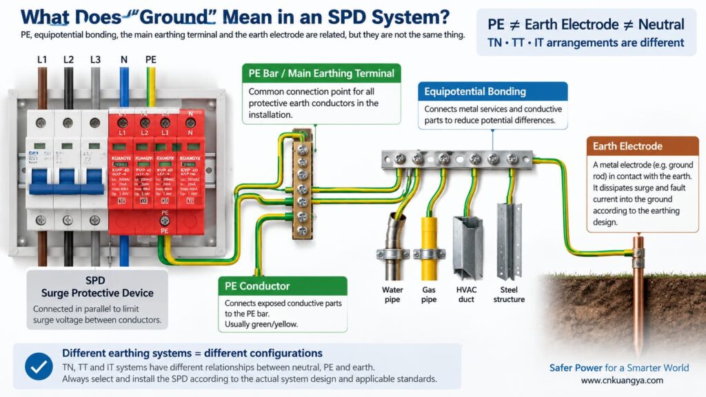
Prima di rispondere alla domanda “può un SPD funzionare senza terra?”, dobbiamo innanzitutto definire cosa significhi effettivamente “terra” in un'installazione elettrica.
Nel linguaggio comune, “terra” può riferirsi a diverse cose:
Il PE è il conduttore di protezione utilizzato per collegare le masse estranee e il sistema di collegamento equipotenziale dell'impianto elettrico. Molti SPD di potenza includono modalità di protezione che fanno riferimento al PE.
Questo è il punto di equipotenzialità all'interno dell'installazione o del quadro di distribuzione in cui i conduttori di protezione sono collegati secondo il progetto del sistema.
Un elettrodo di terra fornisce un collegamento conduttivo tra l'impianto elettrico e la terra. Fa parte del sistema di messa a terra, ma non deve essere confuso con il breve collegamento PE tra un SPD e la barra PE locale.
L'equipotenzialità riduce le pericolose differenze di potenziale tra parti conduttive e servizi. Durante un evento di sovratensione, controllare le differenze di potenziale è spesso più importante che immaginare la corrente di sovratensione come un semplice percorso che scorre lungo un “cavo di terra”.”
La relazione tra neutro e terra dipende dal sistema di messa a terra. I sistemi TN, TT e IT non utilizzano la stessa disposizione neutro/PE, motivo per cui non si deve dare per scontato che la stessa topologia di SPD sia adatta ovunque.
La guida pratica sugli SPD di ABB distingue i sistemi di messa a terra TT, TN-C, TN-S e IT in base a come il neutro di alimentazione e le masse delle apparecchiature sono correlati. La scelta dell'SPD deve quindi essere coordinata con l'impianto elettrico reale piuttosto che basarsi su una regola universale del “cavo di terra”.
Un tipico SPD di potenza è collegato in parallelo al circuito anziché trasportare la normale corrente di carico in serie. In condizioni normali, i suoi elementi di protezione contro le sovratensioni rimangono in uno stato ad alta impedenza. Quando la tensione attraverso una modalità di protezione aumenta a sufficienza, l'SPD diventa conduttivo e limita la tensione deviando la corrente di sovratensione attraverso quel percorso di protezione.
Se desideri prima la spiegazione a livello di circuito, vedi perché un SPD è collegato in parallelo anziché in serie.
"protezione contro le sovratensioni" “deviare la corrente di sovratensione verso terra” è utile come spiegazione semplificata, ma può anche creare un malinteso. Non ogni sovratensione viene gestita da un singolo conduttore che corre direttamente verso un dispersore di terra.
Considera tre comuni modalità di protezione:
| Modalità di protezione | Tensione limitata | Questa modalità utilizza direttamente il PE? |
|---|---|---|
| L–N | Fase rispetto al neutro | Non è richiesto alcun terminale PE diretto per quella specifica modalità |
| L–PE | Fase rispetto alla terra di protezione | Sì |
| N–PE | Neutro rispetto alla terra di protezione | Sì |
| DC+–PE / DC−–PE | Conduttori FV rispetto al PE | Sì |
Questa è la chiave per comprendere la domanda.
Un elemento di protezione L-N può ancora limitare la tensione differenziale tra fase e neutro, anche se tale elemento specifico non è collegato direttamente al PE. Tuttavia, se l'impianto necessita anche di protezione contro le sovratensioni di modo comune rispetto al PE, un percorso L-N da solo non sostituisce le modalità di protezione richieste relative al PE e al sistema di collegamento equipotenziale.
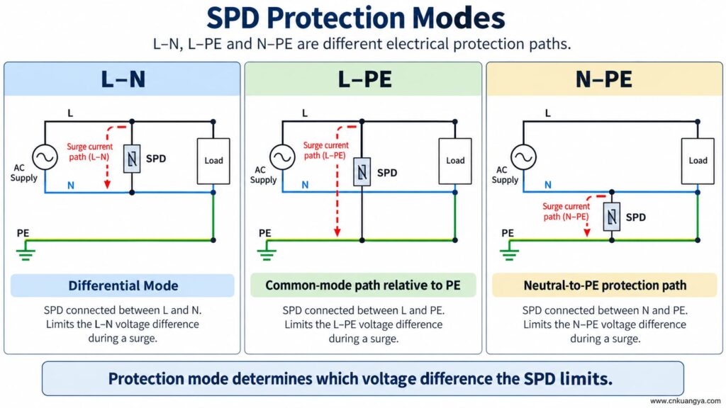
Un SPD può funzionare senza terra o PE? Se l'SPD dispone solo di una modalità di protezione tra conduttori attivi, tale modalità può comunque rispondere a una differenza di potenziale tra quei conduttori. Tuttavia, una modalità di protezione dipendente dal PE non può funzionare come previsto se manca il collegamento al PE.
Ciò significa che entrambe le seguenti affermazioni possono essere vere:
Pertanto, non rimuovere, bypassare o improvvisare mai il collegamento PE semplicemente perché l'SPD mostra ancora un indicatore di stato verde.
La finestra di stato riporta normalmente la condizione di un meccanismo interno monitorato. Non prova che il conduttore PE esterno sia presente, che il sistema di collegamento equipotenziale sia corretto o che la lunghezza del collegamento sia accettabile.
Se un SPD è progettato con percorsi di protezione L–PE, N–PE, DC+–PE o DC−–PE e il collegamento PE si interrompe, tali modalità non dispongono più del collegamento esterno previsto.
Le possibili conseguenze includono:
Un conduttore di protezione mancante non è una scorciatoia per la risoluzione dei problemi dell'SPD. L'installazione deve essere ispezionata e corretta da una persona qualificata in conformità con le istruzioni dell'apparecchiatura e le norme elettriche applicabili.
La risposta alla domanda “un SPD può funzionare senza messa a terra?” cambia perché l'architettura di messa a terra varia nei sistemi TN, TT e IT.
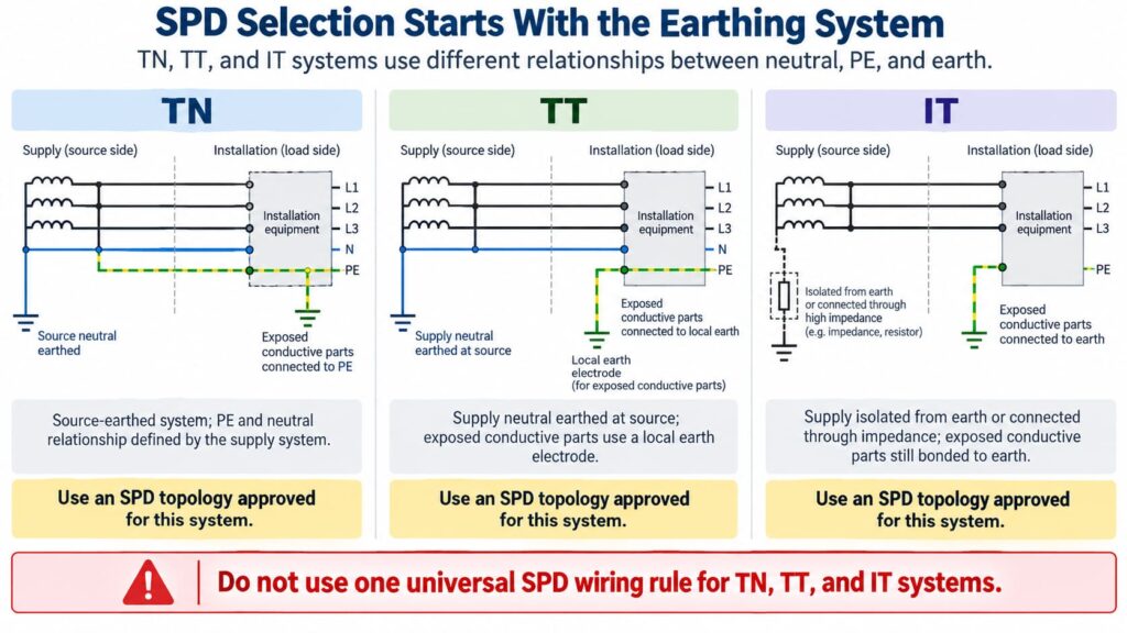
In una configurazione TN-S, il neutro e il PE sono conduttori separati nell'installazione. L'SPD deve essere selezionato e collegato per la configurazione di sistema e le modalità di protezione pertinenti.
Nei sistemi TN-C-S, il conduttore PEN a monte viene suddiviso in N e PE separati in un punto definito. Un SPD installato sulla parte TN-S deve essere idoneo per quella sezione dell'impianto. Lo schema di collegamento esatto deve seguire le istruzioni del prodotto e i requisiti locali.
Non creare un collegamento supplementare tra neutro e terra accanto all'SPD come “migliore messa a terra” improvvisata. Il collegamento tra neutro e PE è una questione di progettazione del sistema, non una modifica sul campo per migliorare le prestazioni dell'SPD.
In a TT system, the installation’s exposed conductive parts are connected to a local earth electrode while the supply neutral has its own source earthing arrangement.
This affects SPD topology, protection modes, temporary overvoltage behavior, and coordination with protective devices. Depending on the design, manufacturers often provide specific TT-compatible SPD arrangements rather than treating a TN model as universally interchangeable.
The correct question is therefore not “Does TT have a ground rod?” but:
Is this SPD and its connection arrangement specifically suitable for the TT system at this installation point?
In an IT system, the supply may be isolated from earth or connected to earth through an impedance, while exposed conductive parts remain earthed according to the installation design.
This creates different voltage conditions, especially during a first insulation fault. An SPD used in an IT system must therefore be explicitly suitable for that system and for the possible continuous and temporary voltages it can experience.
Do not choose an SPD for an IT system solely because its Uc value appears high enough.
For AC SPDs, IEC 61643-11:2025 specifies performance and safety requirements for SPDs connected to AC low-voltage power systems. System selection and installation still require coordination with the actual network and installation rules. See the IEC 61643-11:2025 publication page.
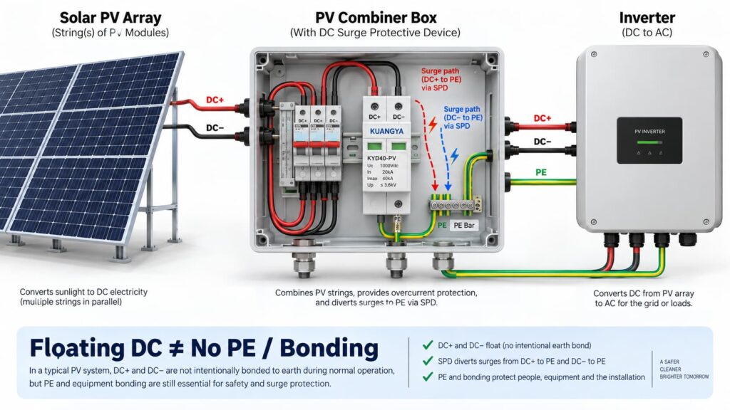
In solar PV systems, the question “can an SPD work without ground?” becomes even more complicated because the DC circuit may be intentionally floating.
Many PV DC circuits operate with neither DC+ nor DC− intentionally bonded directly to earth during normal operation. This is often described as a floating or unearthed DC array.
But that does non mean the whole PV installation has no protective earth, bonding or surge path to PE.
A PV SPD may provide coordinated protection between:
Some PV SPDs use a Y-type internal circuit specifically intended for photovoltaic applications. The correct arrangement depends on the inverter topology, PV earthing arrangement, maximum PV voltage, insulation-monitoring concept and the manufacturer’s approved circuit.
This is why a floating PV system can still use a PE-connected SPD arrangement.
IEC 61643-31 applies to SPDs intended for the DC side of photovoltaic installations up to 1500 V DC and covers their performance characteristics, safety requirements, test methods and ratings. See the IEC 61643-31 publication page.
Before selecting a PV SPD, also verify Ucpv, In, Imax, Up and Iscpv. Our guida alle specifiche degli SPD in corrente continua explains what these markings mean and why the largest kA number is not enough.
No.
A 2P or 3P description does not automatically tell you:
For the same reason, AC module count can also be misleading. If you are comparing neutral/PE arrangements, see our Confronto tra SPD 3+1 e 4+0.
An SPD can be correctly selected and correctly connected to PE, yet still provide poorer installed protection because the connection conductors are too long.
The reason is conductor inductance.
During a fast-rising surge current, additional voltage develops across the SPD connecting conductors:
ΔU = L × di/dt
Dove:
This means the equipment does not necessarily see only the SPD’s datasheet voltage protection level Up. The installed voltage can also include voltage developed across the connection path.
Schneider Electric’s Electrical Installation Guide recommends keeping the total SPD connection length to the network and earth terminal block at no more than approximately 50 cm in the illustrated arrangement and explains the added inductive voltage created by longer conductors. See its SPD connection guidance.
The current consolidated IEC installation standard is IEC 60364-5-53:2019 + Amendment 1:2020 + Amendment 2:2024, which includes Clause 534 for surge protective devices. See the IEC 60364-5-53 consolidated publication page.
If you want a deeper explanation of why conductor length matters during a surge, read our guide on SPD distance from the inverter and connection lead length.
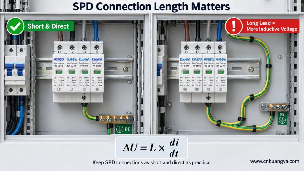
So when asking whether an SPD can work without ground, the quality and length of the PE connection are just as important as whether a protective-earth conductor is physically present.
Trying to reduce lead length by bypassing the approved panel bonding arrangement and connecting an SPD to a separate, isolated earth electrode can create a different problem: the installation may no longer be equipotentially bonded as required.
The correct objective is not “find the nearest piece of earth.”
È:
Connect the SPD to the manufacturer-specified PE/bonding point using the shortest practical, low-impedance path permitted by the system design.
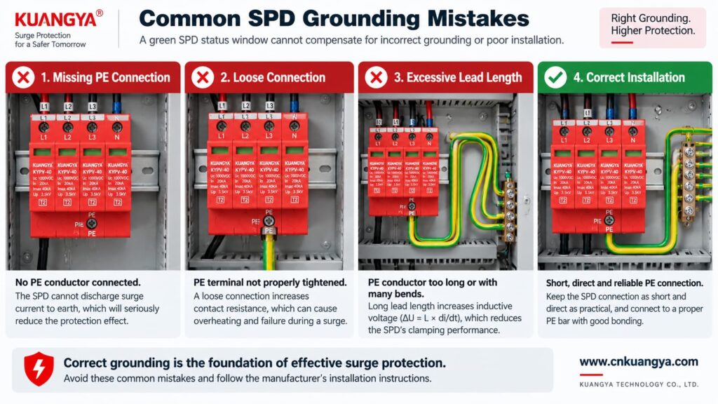
Poor grounding is not one single failure mode. The effect depends on what is actually wrong.
| Problema | Possible Effect | Cosa controllare |
|---|---|---|
| PE conductor missing | PE-dependent protection modes may not function as intended | Wiring diagram, PE continuity, bonding arrangement |
| Loose PE terminal | Unstable/high-impedance surge path, heating or arcing risk under fault conditions | Terminal condition and specified torque |
| Very long SPD connection | Higher installed residual voltage due to inductive voltage | Lead length and routing |
| Large conductor loop | Higher inductive coupling and loop impedance | Routing and loop area |
| Wrong TN/TT/IT SPD topology | Incorrect protection modes or unsuitable voltage stress | System earthing arrangement and manufacturer approval |
| Unbonded conductive systems | Dangerous transient potential differences may remain | Equipotential bonding of incoming services and installation |
| Green SPD indicator but external wiring fault | False confidence | Inspect the complete installation, not only the indicator |
Not by itself.
This is another important distinction.
A low measured earth-electrode resistance can be useful for the earthing system, but SPD performance during a fast transient also depends heavily on:
Therefore, a long conductor to an excellent earth electrode can still develop significant transient voltage during a steep surge current.
For surge protection, think in terms of impedance and equipotential bonding, not only DC or low-frequency resistance.
Can an SPD work without ground when it only protects L–N? It may limit the voltage between L and N if that is an approved protection mode of the device.
However, three cautions are essential.
If a surge raises both L and N relative to PE, an L–N element may see relatively little differential voltage even though the equipment is experiencing a large common-mode voltage relative to earth.
Electronic equipment can have chassis connections, signal cables, communication ports, antennas, shields or other conductive interfaces that create additional surge paths.
Do not intentionally leave a PE terminal disconnected on an SPD that is designed to use it. The correct wiring diagram is part of the product’s protection concept.
A backup fuse or circuit breaker does not replace grounding.
Likewise, grounding does not replace backup overcurrent protection where the SPD manufacturer requires it.
| Component / Function | Main Role |
|---|---|
| SPD | Limits transient overvoltage and diverts surge current through defined protection modes |
| PE / bonding system | Provides protective bonding and reference/discharge paths according to the installation design |
| Backup fuse or circuit breaker | Helps isolate fault current according to the SPD manufacturer’s coordination requirements |
| Earth electrode | Connects the installation earthing system to earth |
| Voltage protection relay / regulator | Addresses longer-duration abnormal voltage depending on device type |
If you are selecting upstream protection, see our practical guide: does an SPD need a backup fuse or circuit breaker?
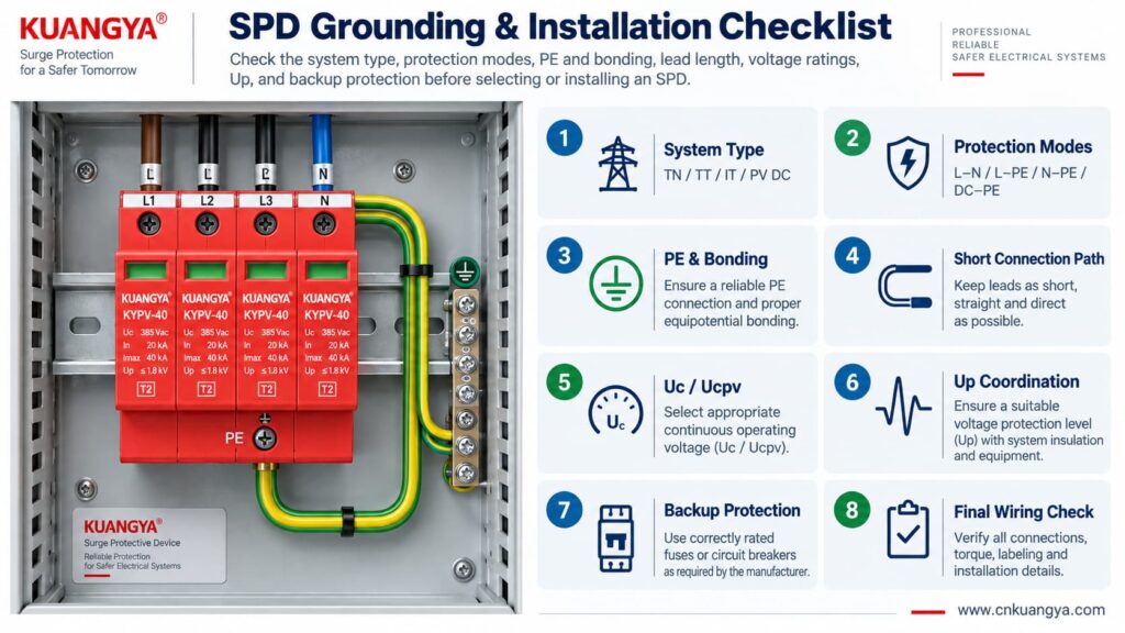
Use the following sequence as a design and inspection checklist. It is not a substitute for local electrical rules or the manufacturer’s instructions.
Confirm whether the circuit is:
Read the internal circuit or wiring diagram, not only the product front label.
Look for protection paths such as L–N, L–PE, N–PE, L1/L2/L3 relationships, DC+–PE and DC−–PE.
Connect only to the approved PE or bonding terminal shown by the manufacturer and installation design.
Avoid unnecessary conductor loops, coils and wide separation between surge-current paths.
For AC, confirm Uc and the applicable system voltage. For PV, confirm Ucpv against the maximum possible PV voltage, including cold-weather Voc where relevant.
Remember that installed protection depends on both the SPD’s Up and the voltage contribution of the connecting conductors.
Verify the manufacturer’s maximum backup fuse / circuit-breaker requirements and the prospective short-circuit conditions.
If an inverter already contains an SPD, do not assume external surge protection is unnecessary. Cable distance, system architecture and the location of the built-in SPD still matter. See our guide on solar inverter built-in SPD and external SPD requirements.
Before deciding whether an SPD can work without ground in a real installation, check the complete protection system rather than judging the SPD alone.
| Controllo | Domanda | Perché è importante |
|---|---|---|
| Sistema | TN, TT, IT, AC or PV DC? | Determines compatible SPD topology |
| Protection modes | Which conductor pairs are protected? | Shows what voltage differences the SPD can limit |
| Collegamento PE | Is PE required and correctly connected? | Essential for PE-dependent protection modes |
| Bonding | Are relevant conductive systems equipotentially bonded? | Reduces dangerous transient potential differences |
| Lead length | Are SPD connections as short and direct as practical? | Reduces added inductive voltage |
| Tensione | Is Uc / Ucpv correct? | Avoids continuous overvoltage stress |
| Protection level | Is Up coordinated with the equipment? | Determines residual voltage stress |
| Surge rating | Are In, Imax and/or Iimp suitable? | Matches expected surge duty |
| Short-circuit conditions | Are SCCR / Iscpv and backup protection suitable? | Important for safe failure and isolation |
| Manufacturer diagram | Does the installed wiring match the approved circuit? | Prevents topology mistakes |
For photovoltaic projects, KUANGYA provides Dispositivi di protezione contro le sovratensioni in corrente continua for different PV voltage classes and installation requirements. Final model selection should always be based on the actual PV voltage, earthing arrangement, protection mode, SPD type and system fault conditions.
Sometimes an individual protection mode such as L–N can operate without a direct PE connection. However, that does not mean the complete surge-protection system can ignore PE, earthing or equipotential bonding. Any SPD mode designed to operate between a live conductor and PE requires the intended PE connection.
When people ask “can an SPD work without ground?”, the answer depends on the SPD circuit rather than on one universal rule. Some devices or protection modes operate only between active conductors, while many power SPDs include PE-related protection modes. Follow the manufacturer’s circuit diagram and select the SPD for the actual TN, TT, IT or DC/PV system.
The SPD may still operate, but a long connection can add inductive voltage during a fast-rising surge current. This can increase the voltage that appears at the protected equipment. Short, direct connections are therefore an important part of SPD installation.
Do not improvise an isolated grounding path simply to make the SPD conductor shorter. The SPD should be connected to the approved PE/bonding point in accordance with the system design, manufacturer instructions and applicable electrical rules.
Not by itself. Surge performance also depends on high-frequency impedance, connection length, conductor routing, loop area, bonding and the SPD’s protection characteristics. A low earth-electrode resistance does not compensate for poor SPD wiring.
Yes. A PV DC system may have neither polarity intentionally grounded during normal operation while still using a properly designed SPD arrangement with protection paths to PE. Use a PV SPD approved for that topology and voltage.
No. A status indicator normally reports the condition of the SPD’s internal monitoring or disconnection mechanism. It does not verify external PE continuity, bonding, conductor length or correct earthing-system selection.
No. An SPD and the installation’s protective-earthing/bonding system perform different functions. A surge protective device should be considered part of a coordinated electrical protection system, not a replacement for protective earthing.
Grounding and bonding are fundamental parts of electrical safety and lightning/surge protection, but they do not perform the same voltage-limiting function as an SPD at equipment terminals. A complete design may require both, depending on the installation.
There is no single standard that answers every installation question. IEC 61643-11 covers AC low-voltage SPD product requirements, IEC 61643-31 covers PV DC SPD product requirements, and IEC 60364-5-53 includes installation requirements for low-voltage electrical installations, including Clause 534 for SPDs. Project-specific lightning-protection and national wiring requirements may also apply.
Un SPD può funzionare senza messa a terra? The answer cannot be reduced to a simple yes or no.
An SPD limits voltage across specific protection modes. A mode between active conductors, such as L–N, may operate without directly using PE. But any protection mode that depends on L–PE, N–PE, DC+–PE or DC−–PE requires the designed PE/bonding path.
More importantly, surge protection is a system function.
A correctly selected SPD can still perform poorly if:
For that reason, do not ask only:
“Does this SPD have a ground terminal?”
Ask instead:
“What voltage differences must be limited, what protection modes does this SPD provide, and how is the complete system bonded and earthed?”
That question leads to a much safer and more technically correct SPD selection.
Technical note: This article is intended for product selection and engineering education. Actual SPD installation must follow the device manufacturer’s wiring instructions, the applicable electrical installation standard, and local code requirements.

