WengYang Industrial Zone Yueqing Wenzhou 325000
Horas de trabalho
De segunda a sexta-feira: das 7h às 19h
Fim de semana: 10:00 - 17:00
WengYang Industrial Zone Yueqing Wenzhou 325000
Horas de trabalho
De segunda a sexta-feira: das 7h às 19h
Fim de semana: 10:00 - 17:00

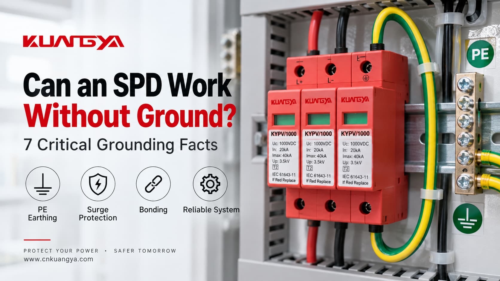
Um DPS pode funcionar sem aterramento? A resposta tecnicamente correta é: às vezes, um modo de proteção específico ainda pode operar sem um caminho PE direto, mas isso não significa que o sistema completo de proteção contra surtos esteja corretamente protegido sem aterramento ou equipotencialização.
Um dispositivo de proteção contra surtos não simplesmente “envia todo surto para o solo”. Ele limita a tensão entre condutores definidos ao tornar-se condutivo quando a tensão em um modo de proteção ultrapassa sua região de operação. Dependendo do projeto do DPS, esses modos de proteção podem incluir fase-neutro (L–N), fase-terra de proteção (L–PE), neutro-terra de proteção (N–PE) ou CC+/CC− para PE.
É por isso que a questão é mais complexa do que “aterrado ou não aterrado”. As verdadeiras questões de engenharia são:
Se o problema que você está tentando resolver não é o aterramento, mas a diferença entre um surto transitório e um problema de tensão de longa duração, leia primeiro um DPS protege contra sobretensão. O aterramento não pode transformar um DPS em um regulador de tensão ou em um relé de sobretensão geral.
Um DPS pode funcionar sem aterramento? Uma resposta melhor é: depende do que se entende por “aterramento” e de qual modo de proteção do DPS está sendo discutido.
| Situação | O DPS ainda pode fazer algo? | Preocupação principal |
|---|---|---|
| Modo de proteção L–N sem conexão direta com o PE nesse modo | Potencialmente sim | Apenas a tensão em modo diferencial entre L e N está sendo limitada |
| Modo de proteção L–PE ou N–PE com ausência de PE | Não conforme pretendido | O caminho de proteção projetado está incompleto ou incorreto |
| O PE existe, mas a conexão é excessivamente longa | O DPS ainda pode operar | Tensão indutiva adicional pode aumentar o nível de proteção instalado |
| DPS incorreto para o sistema de aterramento TN/TT/IT | Não assuma uma proteção correta | Os modos de proteção, o estresse por TOV e as condições de falha podem não corresponder ao sistema |
| Sistema fotovoltaico CC flutuante | Sim, com um arranjo de DPS fotovoltaico projetado corretamente | “CC flutuante” não significa que o PE e a equipotencialização podem ser ignorados |
| Aterramento ineficaz / conexão PE danificada | A proteção pode ser seriamente comprometida | Diferenças de potencial podem permanecer entre sistemas condutores |
A regra mais importante é:
Não decida se um DPS “precisa de aterramento” olhando apenas para o número de módulos. Identifique o esquema de aterramento do sistema e os modos de proteção reais do DPS.
Esta é a mesma razão pela qual um DPS fotovoltaico 2P ou 3P não deve ser selecionado apenas pela aparência. O nosso Guia de DPS CC 2P vs 3P explica por que a contagem de módulos, condutores protegidos, conexão PE e caminhos de proteção interna são conceitos diferentes.
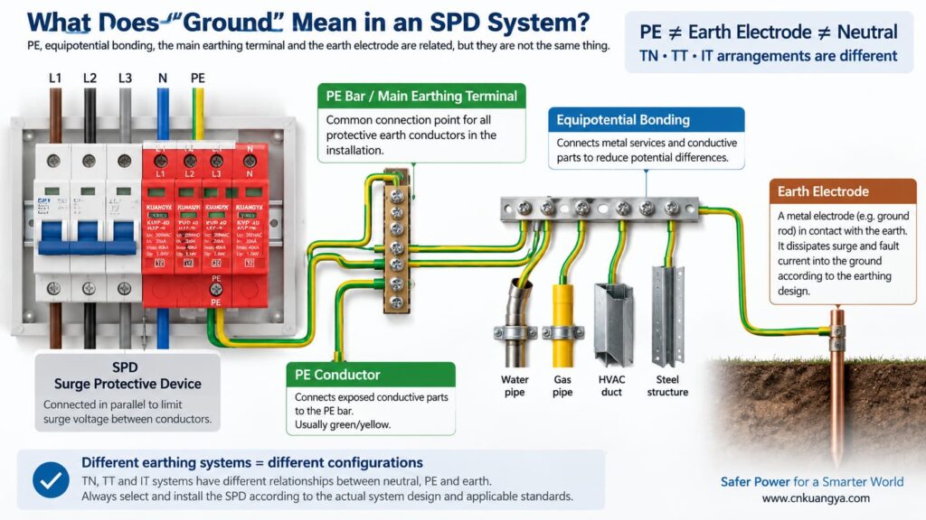
Antes de responder “um DPS pode funcionar sem terra?”, precisamos primeiro definir o que “terra” realmente significa em uma instalação elétrica.
Em conversas cotidianas, “terra” pode se referir a várias coisas diferentes:
PE é o condutor de proteção utilizado para conectar partes condutoras expostas ao sistema de equipotencialidade da instalação elétrica. Muitos DPS (Dispositivos de Proteção contra Surtos) incluem modos de proteção referenciados ao PE.
Este é o ponto de equipotencialidade dentro da instalação ou do quadro de distribuição onde os condutores de proteção são conectados de acordo com o projeto do sistema.
Um eletrodo de aterramento fornece uma conexão condutiva entre a instalação elétrica e a terra. Ele faz parte do sistema de aterramento, mas não deve ser confundido com a conexão PE curta entre um DPS e a barra de PE local.
A equipotencialização reduz diferenças de potencial perigosas entre partes condutivas e utilidades. Durante um evento de surto, controlar as diferenças de potencial é frequentemente mais importante do que imaginar a corrente de surto seguindo um caminho simples “descendo por um fio terra”.”
A relação entre neutro e terra depende do sistema de aterramento. Os sistemas TN, TT e IT não utilizam o mesmo arranjo de neutro/PE, o que é uma das razões pelas quais não se deve assumir que a mesma topologia de DPS seja adequada para todos os locais.
A orientação prática da ABB sobre DPS distingue os sistemas de aterramento TT, TN-C, TN-S e IT de acordo com a forma como o neutro da alimentação e os aterramentos dos equipamentos estão relacionados. Portanto, a seleção do DPS deve ser coordenada com o sistema elétrico real, em vez de baseada em uma regra universal de “fio terra”.
Um DPS de potência típico é conectado em paralelo com o circuito, em vez de transportar a corrente de carga normal em série. Em condições normais, seus elementos de proteção contra surtos permanecem em um estado de alta impedância. Quando a tensão através de um modo de proteção aumenta suficientemente, o DPS torna-se condutivo e limita a tensão desviando a corrente de surto através desse caminho de proteção.
Se você deseja a explicação em nível de circuito primeiro, veja por que um DPS é conectado em paralelo em vez de em série.
A expressão “desviar a corrente de surto para o terra” é útil como uma explicação simplificada, mas também pode criar um mal-entendido. Nem todo surto é tratado por um condutor que vai diretamente para uma haste de aterramento.
Considere três modos de proteção comuns:
| Modo de proteção | Tensão Sendo Limitada | Este Modo Utiliza Diretamente o PE? |
|---|---|---|
| L–N | Fase em relação ao neutro | Nenhum terminal de PE direto é necessário para esse modo individual |
| L–PE | Fase em relação à terra de proteção | Sim |
| N–PE | Neutro em relação à terra de proteção | Sim |
| CC+–PE / CC−–PE | Condutores fotovoltaicos (PV) em relação ao PE | Sim |
Esta é a chave para entender a questão.
Um elemento de proteção L–N ainda pode limitar a tensão diferencial entre fase e neutro, mesmo que esse elemento específico não esteja conectado diretamente ao PE. No entanto, se a instalação também necessitar de proteção contra sobretensão de modo comum em relação ao PE, um caminho L–N isolado não substitui os modos de proteção relacionados ao PE e o sistema de equipotencialização necessários.
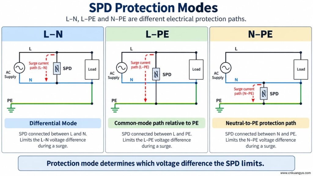
Um DPS pode funcionar sem terra ou PE? Se o DPS possuir apenas um modo de proteção entre condutores ativos, esse modo ainda poderá responder a uma diferença de potencial entre esses condutores. Contudo, um modo de proteção dependente de PE não pode operar conforme projetado se a sua conexão ao PE estiver ausente.
Isso significa que duas afirmações podem ser verdadeiras ao mesmo tempo:
Portanto, nunca remova, ignore ou improvise a conexão PE simplesmente porque um DPS ainda mostra um indicador de status verde.
A janela de status normalmente informa a condição de um mecanismo interno monitorado. Ela não prova que o condutor PE externo existe, que o sistema de equipotencialização está correto ou que o comprimento da conexão é aceitável.
Se um DPS for projetado com caminhos de proteção L–PE, N–PE, DC+–PE ou DC−–PE e a conexão PE se tornar aberta, esses modos deixam de ter a conexão externa pretendida.
As possíveis consequências incluem:
Um condutor de proteção ausente não é um atalho para a resolução de problemas de um DPS. A instalação deve ser inspecionada e corrigida por uma pessoa qualificada, de acordo com as instruções do equipamento e as normas elétricas aplicáveis.
A resposta para “um DPS pode funcionar sem aterramento?” muda porque a arquitetura de aterramento muda nos sistemas TN, TT e IT.
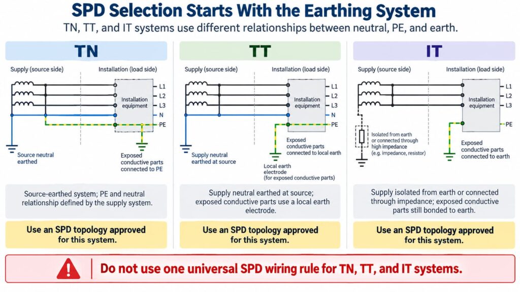
Em um arranjo TN-S, o neutro e o PE são condutores separados na instalação. O DPS deve ser selecionado e conectado para a configuração de sistema e modos de proteção relevantes.
Em sistemas TN-C-S, o condutor PEN a montante é dividido em N e PE separados num ponto definido. Um DPS instalado na parte TN-S deve ser adequado para essa parte do sistema. O esquema de ligação exato deve seguir as instruções do produto e os requisitos locais.
Não crie uma ligação neutro-terra adicional junto ao DPS como um “melhor aterramento” improvisado. A equipotencialização entre neutro e PE é uma questão de projeto do sistema, não uma modificação de campo para melhorar o desempenho do DPS.
In a TT system, the installation’s exposed conductive parts are connected to a local earth electrode while the supply neutral has its own source earthing arrangement.
This affects SPD topology, protection modes, temporary overvoltage behavior, and coordination with protective devices. Depending on the design, manufacturers often provide specific TT-compatible SPD arrangements rather than treating a TN model as universally interchangeable.
The correct question is therefore not “Does TT have a ground rod?” but:
Is this SPD and its connection arrangement specifically suitable for the TT system at this installation point?
In an IT system, the supply may be isolated from earth or connected to earth through an impedance, while exposed conductive parts remain earthed according to the installation design.
This creates different voltage conditions, especially during a first insulation fault. An SPD used in an IT system must therefore be explicitly suitable for that system and for the possible continuous and temporary voltages it can experience.
Do not choose an SPD for an IT system solely because its Uc value appears high enough.
For AC SPDs, IEC 61643-11:2025 specifies performance and safety requirements for SPDs connected to AC low-voltage power systems. System selection and installation still require coordination with the actual network and installation rules. See the IEC 61643-11:2025 publication page.
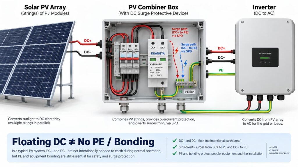
In solar PV systems, the question “can an SPD work without ground?” becomes even more complicated because the DC circuit may be intentionally floating.
Many PV DC circuits operate with neither DC+ nor DC− intentionally bonded directly to earth during normal operation. This is often described as a floating or unearthed DC array.
But that does não mean the whole PV installation has no protective earth, bonding or surge path to PE.
A PV SPD may provide coordinated protection between:
Some PV SPDs use a Y-type internal circuit specifically intended for photovoltaic applications. The correct arrangement depends on the inverter topology, PV earthing arrangement, maximum PV voltage, insulation-monitoring concept and the manufacturer’s approved circuit.
This is why a floating PV system can still use a PE-connected SPD arrangement.
IEC 61643-31 applies to SPDs intended for the DC side of photovoltaic installations up to 1500 V DC and covers their performance characteristics, safety requirements, test methods and ratings. See the IEC 61643-31 publication page.
Before selecting a PV SPD, also verify Ucpv, In, Imax, Up and Iscpv. Our Guia de especificações de DPS CC explains what these markings mean and why the largest kA number is not enough.
Não.
A 2P or 3P description does not automatically tell you:
For the same reason, AC module count can also be misleading. If you are comparing neutral/PE arrangements, see our Comparação de DPS 3+1 vs 4+0.
An SPD can be correctly selected and correctly connected to PE, yet still provide poorer installed protection because the connection conductors are too long.
The reason is conductor inductance.
During a fast-rising surge current, additional voltage develops across the SPD connecting conductors:
ΔU = L × di/dt
Onde:
This means the equipment does not necessarily see only the SPD’s datasheet voltage protection level Up. The installed voltage can also include voltage developed across the connection path.
Schneider Electric’s Electrical Installation Guide recommends keeping the total SPD connection length to the network and earth terminal block at no more than approximately 50 cm in the illustrated arrangement and explains the added inductive voltage created by longer conductors. See its SPD connection guidance.
The current consolidated IEC installation standard is IEC 60364-5-53:2019 + Amendment 1:2020 + Amendment 2:2024, which includes Clause 534 for surge protective devices. See the IEC 60364-5-53 consolidated publication page.
If you want a deeper explanation of why conductor length matters during a surge, read our guide on SPD distance from the inverter and connection lead length.
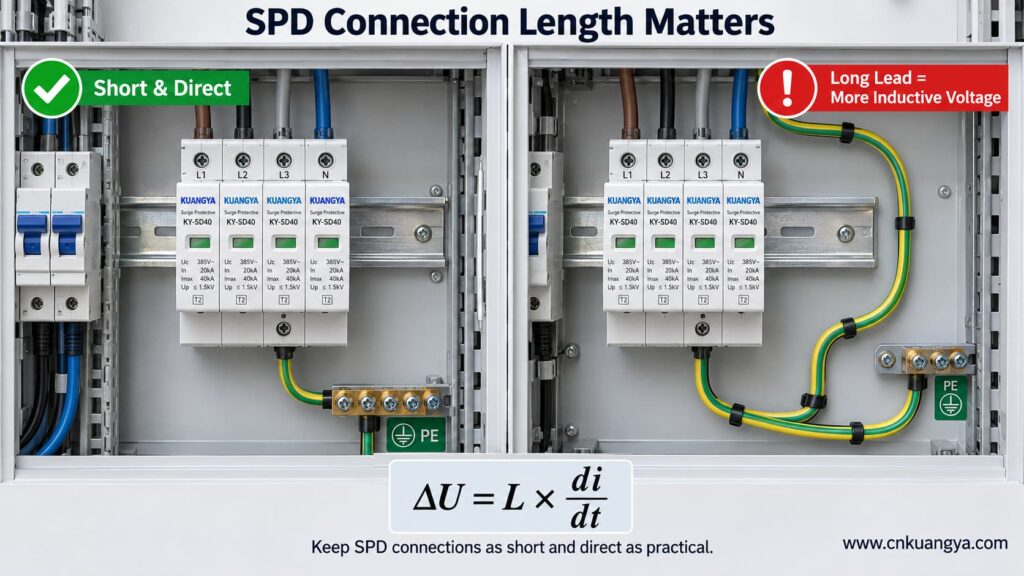
So when asking whether an SPD can work without ground, the quality and length of the PE connection are just as important as whether a protective-earth conductor is physically present.
Trying to reduce lead length by bypassing the approved panel bonding arrangement and connecting an SPD to a separate, isolated earth electrode can create a different problem: the installation may no longer be equipotentially bonded as required.
The correct objective is not “find the nearest piece of earth.”
É:
Connect the SPD to the manufacturer-specified PE/bonding point using the shortest practical, low-impedance path permitted by the system design.
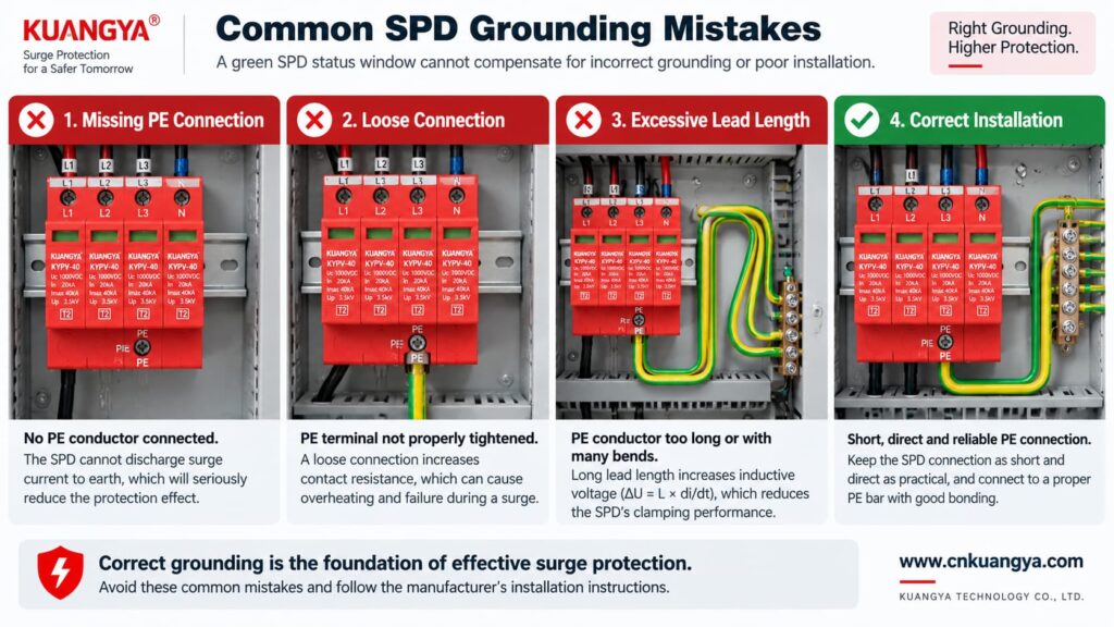
Poor grounding is not one single failure mode. The effect depends on what is actually wrong.
| Problema | Possible Effect | O que verificar |
|---|---|---|
| PE conductor missing | PE-dependent protection modes may not function as intended | Wiring diagram, PE continuity, bonding arrangement |
| Loose PE terminal | Unstable/high-impedance surge path, heating or arcing risk under fault conditions | Terminal condition and specified torque |
| Very long SPD connection | Higher installed residual voltage due to inductive voltage | Lead length and routing |
| Large conductor loop | Higher inductive coupling and loop impedance | Routing and loop area |
| Wrong TN/TT/IT SPD topology | Incorrect protection modes or unsuitable voltage stress | System earthing arrangement and manufacturer approval |
| Unbonded conductive systems | Dangerous transient potential differences may remain | Equipotential bonding of incoming services and installation |
| Green SPD indicator but external wiring fault | False confidence | Inspect the complete installation, not only the indicator |
Not by itself.
This is another important distinction.
A low measured earth-electrode resistance can be useful for the earthing system, but SPD performance during a fast transient also depends heavily on:
Therefore, a long conductor to an excellent earth electrode can still develop significant transient voltage during a steep surge current.
For surge protection, think in terms of impedance and equipotential bonding, not only DC or low-frequency resistance.
Can an SPD work without ground when it only protects L–N? It may limit the voltage between L and N if that is an approved protection mode of the device.
However, three cautions are essential.
If a surge raises both L and N relative to PE, an L–N element may see relatively little differential voltage even though the equipment is experiencing a large common-mode voltage relative to earth.
Electronic equipment can have chassis connections, signal cables, communication ports, antennas, shields or other conductive interfaces that create additional surge paths.
Do not intentionally leave a PE terminal disconnected on an SPD that is designed to use it. The correct wiring diagram is part of the product’s protection concept.
A backup fuse or circuit breaker does not replace grounding.
Likewise, grounding does not replace backup overcurrent protection where the SPD manufacturer requires it.
| Component / Function | Main Role |
|---|---|
| DPS | Limits transient overvoltage and diverts surge current through defined protection modes |
| PE / bonding system | Provides protective bonding and reference/discharge paths according to the installation design |
| Backup fuse or circuit breaker | Helps isolate fault current according to the SPD manufacturer’s coordination requirements |
| Earth electrode | Connects the installation earthing system to earth |
| Voltage protection relay / regulator | Addresses longer-duration abnormal voltage depending on device type |
If you are selecting upstream protection, see our practical guide: does an SPD need a backup fuse or circuit breaker?
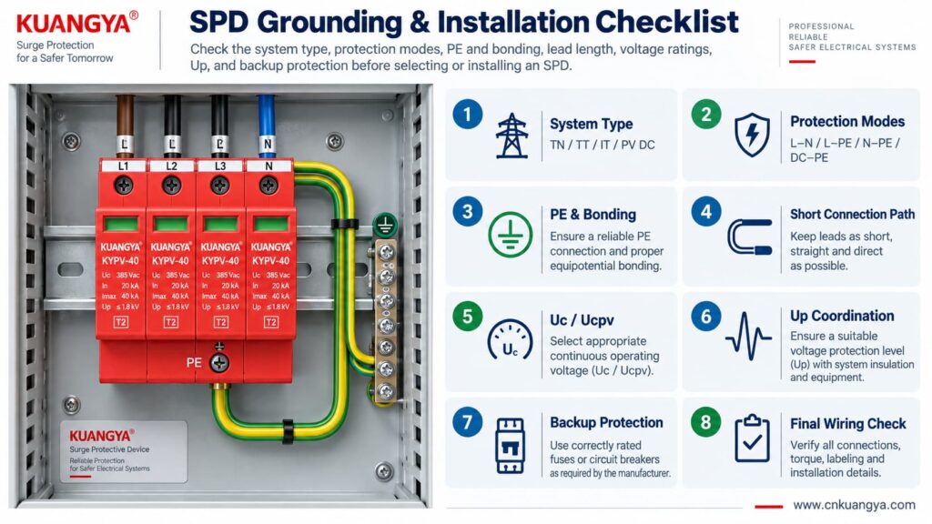
Use the following sequence as a design and inspection checklist. It is not a substitute for local electrical rules or the manufacturer’s instructions.
Confirm whether the circuit is:
Read the internal circuit or wiring diagram, not only the product front label.
Look for protection paths such as L–N, L–PE, N–PE, L1/L2/L3 relationships, DC+–PE and DC−–PE.
Connect only to the approved PE or bonding terminal shown by the manufacturer and installation design.
Avoid unnecessary conductor loops, coils and wide separation between surge-current paths.
For AC, confirm Uc and the applicable system voltage. For PV, confirm Ucpv against the maximum possible PV voltage, including cold-weather Voc where relevant.
Remember that installed protection depends on both the SPD’s Up and the voltage contribution of the connecting conductors.
Verify the manufacturer’s maximum backup fuse / circuit-breaker requirements and the prospective short-circuit conditions.
If an inverter already contains an SPD, do not assume external surge protection is unnecessary. Cable distance, system architecture and the location of the built-in SPD still matter. See our guide on solar inverter built-in SPD and external SPD requirements.
Before deciding whether an SPD can work without ground in a real installation, check the complete protection system rather than judging the SPD alone.
| Verificar | Pergunta | Por que é importante |
|---|---|---|
| Sistema | TN, TT, IT, AC or PV DC? | Determines compatible SPD topology |
| Modos de proteção | Which conductor pairs are protected? | Shows what voltage differences the SPD can limit |
| Ligação PE | Is PE required and correctly connected? | Essential for PE-dependent protection modes |
| Bonding | Are relevant conductive systems equipotentially bonded? | Reduces dangerous transient potential differences |
| Lead length | Are SPD connections as short and direct as practical? | Reduces added inductive voltage |
| Tensão | Is Uc / Ucpv correct? | Avoids continuous overvoltage stress |
| Protection level | Is Up coordinated with the equipment? | Determines residual voltage stress |
| Surge rating | Are In, Imax and/or Iimp suitable? | Matches expected surge duty |
| Short-circuit conditions | Are SCCR / Iscpv and backup protection suitable? | Important for safe failure and isolation |
| Manufacturer diagram | Does the installed wiring match the approved circuit? | Prevents topology mistakes |
For photovoltaic projects, KUANGYA provides Dispositivos de proteção contra surtos de corrente contínua for different PV voltage classes and installation requirements. Final model selection should always be based on the actual PV voltage, earthing arrangement, protection mode, SPD type and system fault conditions.
Sometimes an individual protection mode such as L–N can operate without a direct PE connection. However, that does not mean the complete surge-protection system can ignore PE, earthing or equipotential bonding. Any SPD mode designed to operate between a live conductor and PE requires the intended PE connection.
When people ask “can an SPD work without ground?”, the answer depends on the SPD circuit rather than on one universal rule. Some devices or protection modes operate only between active conductors, while many power SPDs include PE-related protection modes. Follow the manufacturer’s circuit diagram and select the SPD for the actual TN, TT, IT or DC/PV system.
The SPD may still operate, but a long connection can add inductive voltage during a fast-rising surge current. This can increase the voltage that appears at the protected equipment. Short, direct connections are therefore an important part of SPD installation.
Do not improvise an isolated grounding path simply to make the SPD conductor shorter. The SPD should be connected to the approved PE/bonding point in accordance with the system design, manufacturer instructions and applicable electrical rules.
Not by itself. Surge performance also depends on high-frequency impedance, connection length, conductor routing, loop area, bonding and the SPD’s protection characteristics. A low earth-electrode resistance does not compensate for poor SPD wiring.
Yes. A PV DC system may have neither polarity intentionally grounded during normal operation while still using a properly designed SPD arrangement with protection paths to PE. Use a PV SPD approved for that topology and voltage.
No. A status indicator normally reports the condition of the SPD’s internal monitoring or disconnection mechanism. It does not verify external PE continuity, bonding, conductor length or correct earthing-system selection.
No. An SPD and the installation’s protective-earthing/bonding system perform different functions. A surge protective device should be considered part of a coordinated electrical protection system, not a replacement for protective earthing.
Grounding and bonding are fundamental parts of electrical safety and lightning/surge protection, but they do not perform the same voltage-limiting function as an SPD at equipment terminals. A complete design may require both, depending on the installation.
There is no single standard that answers every installation question. IEC 61643-11 covers AC low-voltage SPD product requirements, IEC 61643-31 covers PV DC SPD product requirements, and IEC 60364-5-53 includes installation requirements for low-voltage electrical installations, including Clause 534 for SPDs. Project-specific lightning-protection and national wiring requirements may also apply.
Um DPS pode funcionar sem aterramento? The answer cannot be reduced to a simple yes or no.
An SPD limits voltage across specific protection modes. A mode between active conductors, such as L–N, may operate without directly using PE. But any protection mode that depends on L–PE, N–PE, DC+–PE or DC−–PE requires the designed PE/bonding path.
More importantly, surge protection is a system function.
A correctly selected SPD can still perform poorly if:
For that reason, do not ask only:
“Does this SPD have a ground terminal?”
Ask instead:
“What voltage differences must be limited, what protection modes does this SPD provide, and how is the complete system bonded and earthed?”
That question leads to a much safer and more technically correct SPD selection.
Technical note: This article is intended for product selection and engineering education. Actual SPD installation must follow the device manufacturer’s wiring instructions, the applicable electrical installation standard, and local code requirements.

