WengYang Industriegebiet Yueqing Wenzhou 325000
Arbeitszeiten
Montag bis Freitag: 7AM - 7PM
Am Wochenende: 10AM - 5PM
WengYang Industriegebiet Yueqing Wenzhou 325000
Arbeitszeiten
Montag bis Freitag: 7AM - 7PM
Am Wochenende: 10AM - 5PM

Kann ein SPD ohne Erdung funktionieren? Die technisch korrekte Antwort lautet: Manchmal kann ein bestimmter Schutzmodus auch ohne direkten PE-Pfad funktionieren, aber das bedeutet nicht, dass das gesamte Überspannungsschutzsystem ohne Erdung oder Potenzialausgleich korrekt geschützt ist.
Ein Überspannungsschutzgerät leitet nicht einfach “jede Überspannung in den Boden ab”. Es begrenzt die Spannung zwischen definierten Leitern, indem es leitfähig wird, sobald die Spannung über einem Schutzmodus den Betriebsbereich überschreitet. Je nach SPD-Ausführung können diese Schutzmodi Leiter gegen Neutralleiter (L–N), Leiter gegen Schutzleiter (L–PE), Neutralleiter gegen Schutzleiter (N–PE) oder DC+/DC− gegen PE umfassen.
Deshalb ist die Frage komplexer als nur “geerdet oder nicht geerdet”. Die eigentlichen technischen Fragen lauten:
Wenn das Problem, das Sie lösen möchten, nicht die Erdung ist, sondern der Unterschied zwischen einem transienten Stoß und einem länger anhaltenden Spannungsproblem, lesen Sie zuerst schützt ein SPD vor Überspannung. Eine Erdung kann aus einem SPD keinen Spannungsregler oder ein allgemeines Überspannungsrelais machen.
Kann ein Überspannungsschutzgerät (SPD) ohne Erdung funktionieren? Eine bessere Antwort lautet: Es kommt darauf an, was mit “Erdung” gemeint ist und welcher Schutzmodus des SPD diskutiert wird.
| Situation | Kann das SPD trotzdem noch etwas bewirken? | Hauptbedenken |
|---|---|---|
| L-N-Schutzmodus ohne direkte PE-Verbindung in diesem Modus | Möglicherweise ja | Nur die Differenzspannung zwischen L und N wird begrenzt |
| L-PE- oder N-PE-Schutzmodus bei fehlendem PE | Nicht bestimmungsgemäß | Der vorgesehene Schutzpfad ist unvollständig oder fehlerhaft |
| PE ist vorhanden, aber die Verbindung ist übermäßig lang | SPD kann weiterhin auslösen | Zusätzliche induktive Spannung kann das installierte Schutzniveau erhöhen |
| Falscher SPD für das TN/TT/IT-Erdungssystem | Gehen Sie nicht von einem korrekten Schutz aus | Schutzmodi, TOV-Belastung und Fehlerbedingungen stimmen möglicherweise nicht mit dem System überein |
| Schwimmendes PV-Gleichstromsystem | Ja, mit einer korrekt ausgelegten PV-SPD-Anordnung | “Schwimmender Gleichstrom” bedeutet nicht, dass PE und Potenzialausgleich ignoriert werden können |
| Keine wirksame Erdung / beschädigter PE-Anschluss | Der Schutz kann ernsthaft beeinträchtigt sein | Potenzialunterschiede können zwischen leitfähigen Systemen bestehen bleiben |
Die wichtigste Regel lautet:
Entscheiden Sie nicht allein anhand der Modulanzahl, ob ein SPD “geerdet werden muss”. Identifizieren Sie das Systemerdungskonzept und die tatsächlichen Schutzmodi des SPD.
Dies ist der gleiche Grund, warum ein 2P- oder 3P-PV-ÜSS nicht allein nach dem Aussehen ausgewählt werden sollte. Unser Leitfaden für 2P- vs. 3P-DC-ÜSS erklärt, warum Modulanzahl, geschützte Leiter, PE-Anschluss und interne Schutzpfade unterschiedliche Konzepte sind.
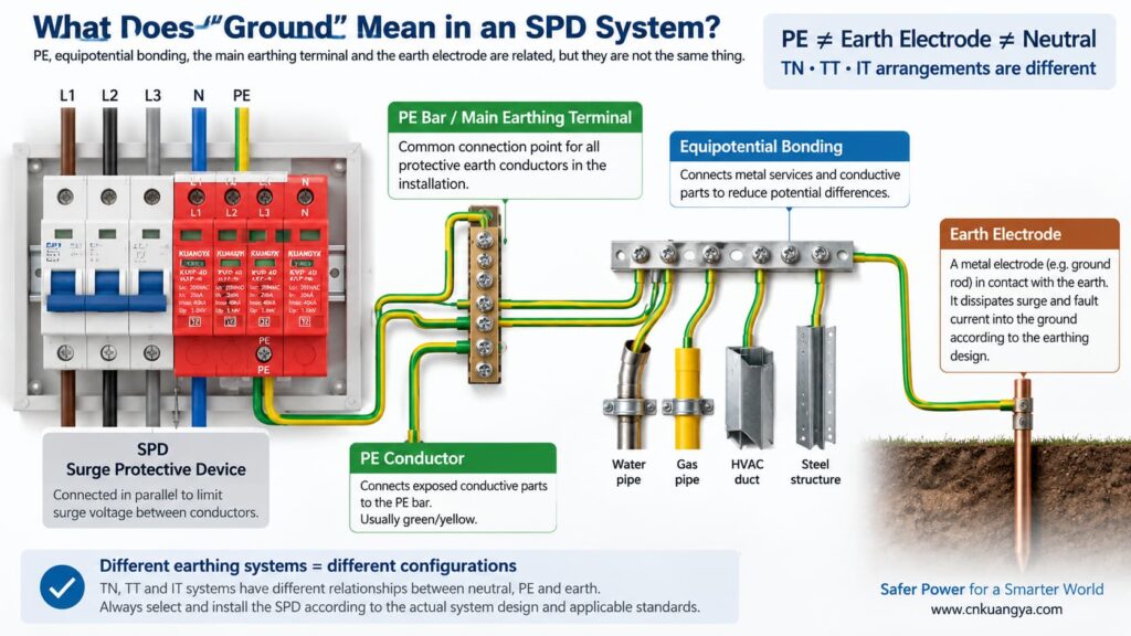
Bevor wir die Frage beantworten, ob ein ÜSS ohne Erdung funktionieren kann, müssen wir zunächst definieren, was “Erde” in einer elektrischen Anlage tatsächlich bedeutet.
Im alltäglichen Sprachgebrauch kann sich “Erde” auf verschiedene Dinge beziehen:
PE ist der Schutzleiter, der dazu dient, berührbare leitfähige Teile mit dem Schutzpotentialausgleich der elektrischen Anlage zu verbinden. Viele Überspannungsschutzgeräte (SPDs) verfügen über Schutzmodi, die sich auf den PE beziehen.
Dies ist der Anschlusspunkt innerhalb der Installations- oder Verteilerbaugruppe, an dem Schutzleiter gemäß dem Systemdesign angeschlossen werden.
Eine Erdungselektrode stellt eine leitfähige Verbindung zwischen der elektrischen Anlage und der Erde her. Sie ist Teil des Erdungssystems, sollte jedoch nicht mit der kurzen PE-Verbindung zwischen einem SPD und der lokalen PE-Schiene verwechselt werden.
Potenzialausgleich reduziert gefährliche Spannungsunterschiede zwischen leitfähigen Teilen und Versorgungsleitungen. Während eines Überspannungsereignisses ist die Kontrolle von Potenzialunterschieden oft wichtiger, als sich vorzustellen, dass der Überspannungsstrom einen einfachen Weg “über ein Erdungskabel” nimmt.”
Die Beziehung zwischen Neutralleiter und Erde hängt vom Erdungssystem ab. TN-, TT- und IT-Systeme verwenden nicht dieselbe Neutralleiter-/PE-Anordnung, was ein Grund dafür ist, dass nicht davon ausgegangen werden sollte, dass dieselbe SPD-Topologie überall geeignet ist.
Die praktischen SPD-Leitfäden von ABB unterscheiden zwischen TT-, TN-C-, TN-S- und IT-Erdungssystemen, je nachdem, wie der Neutralleiter der Versorgung und die Schutzerdung der Geräte zueinander in Beziehung stehen. Die Auswahl des SPD muss daher auf das tatsächliche elektrische System abgestimmt sein und darf nicht auf einer universellen “Erdungskabel”-Regel basieren.
Ein typischer Überspannungsschutz (SPD) wird parallel zum Stromkreis geschaltet, anstatt den normalen Laststrom in Reihe zu führen. Unter normalen Bedingungen verbleiben die Schutzelemente in einem hochohmigen Zustand. Wenn die Spannung an einem Schutzpfad ausreichend ansteigt, wird der SPD leitfähig und begrenzt die Spannung, indem er den Stoßstrom über diesen Schutzpfad ableitet.
Wenn Sie zuerst die Erklärung auf Schaltungsebene wünschen, siehe warum ein SPD parallel statt in Reihe geschaltet wird.
Der Begriff “Stoßstrom zur Erde ableiten” ist als vereinfachte Erklärung nützlich, kann aber auch zu Missverständnissen führen. Nicht jeder Stoßstrom wird über einen einzelnen Leiter direkt zu einem Erder abgeleitet.
Betrachten Sie drei gängige Schutzmodi:
| Schutzmodus | Begrenzte Spannung | Nutzt dieser Modus direkt den PE? |
|---|---|---|
| L–N | Außenleiter gegenüber Neutralleiter | Für diesen spezifischen Modus ist kein direkter PE-Anschluss erforderlich |
| L–PE | Außenleiter gegenüber Schutzleiter | Ja |
| N–PE | Neutralleiter gegenüber Schutzleiter | Ja |
| DC+–PE / DC−–PE | PV-Leiter in Bezug auf PE | Ja |
Dies ist der Schlüssel zum Verständnis der Frage.
Ein L-N-Schutzelement kann zwar weiterhin die Differenzspannung zwischen Außenleiter und Neutralleiter begrenzen, auch wenn dieses spezifische Element nicht direkt mit PE verbunden ist. Wenn die Installation jedoch auch einen Schutz gegen Gleichtakt-Überspannungen in Bezug auf PE erfordert, ersetzt ein reiner L-N-Pfad nicht die erforderlichen PE-bezogenen Schutzmodi und das Potenzialausgleichssystem.
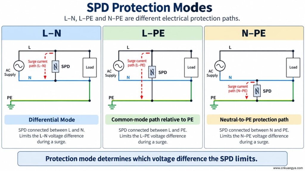
Kann ein SPD ohne Erde oder PE funktionieren? Wenn das SPD nur einen Schutzmodus zwischen aktiven Leitern aufweist, kann dieser Modus dennoch auf eine Spannungsdifferenz zwischen diesen Leitern reagieren. Ein PE-abhängiger Schutzmodus kann jedoch nicht wie vorgesehen funktionieren, wenn die PE-Verbindung fehlt.
Das bedeutet, dass beide Aussagen wahr sein können:
Entfernen, überbrücken oder improvisieren Sie daher niemals die PE-Verbindung, nur weil ein SPD noch eine grüne Statusanzeige aufweist.
Das Statusfenster zeigt normalerweise den Zustand eines überwachten internen Mechanismus an. Es beweist nicht, dass der externe PE-Leiter vorhanden ist, dass das Potentialausgleichssystem korrekt ausgeführt wurde oder dass die Leitungslänge akzeptabel ist.
Wenn ein SPD mit L–PE-, N–PE-, DC+–PE- oder DC−–PE-Schutzpfaden ausgelegt ist und die PE-Verbindung unterbrochen wird, verfügen diese Modi nicht mehr über die beabsichtigte externe Verbindung.
Mögliche Konsequenzen sind:
Ein fehlender Schutzleiter ist keine Abkürzung bei der Fehlersuche an einem SPD. Die Installation sollte von einer qualifizierten Person gemäß den Geräteanweisungen und den geltenden elektrotechnischen Regeln überprüft und korrigiert werden.
Die Antwort auf die Frage “Kann ein SPD ohne Erdung funktionieren?” variiert, da sich die Erdungsarchitektur in TN-, TT- und IT-Systemen unterscheidet.
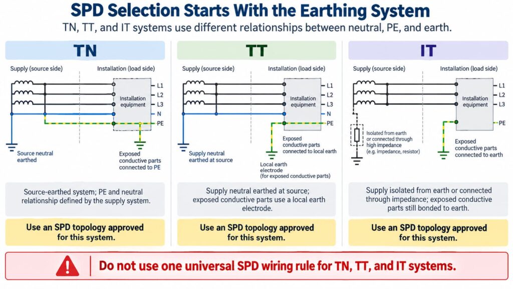
In einer TN-S-Anordnung sind Neutralleiter und PE in der Installation getrennte Leiter. Der SPD muss für die entsprechende Systemkonfiguration und die Schutzmodi ausgewählt und angeschlossen werden.
In TN-C-S-Systemen wird der vorgelagerte PEN-Leiter an einem definierten Punkt in getrennte N- und PE-Leiter aufgeteilt. Ein im TN-S-Teil installierter SPD muss für diesen Teil des Systems geeignet sein. Die genaue Anschlussanordnung sollte den Produktanweisungen und den örtlichen Anforderungen entsprechen.
Do not create an extra neutral-to-earth link beside the SPD as an improvised “better ground.” Neutral/PE bonding is a system-design issue, not a field modification to improve SPD performance.
In a TT system, the installation’s exposed conductive parts are connected to a local earth electrode while the supply neutral has its own source earthing arrangement.
This affects SPD topology, protection modes, temporary overvoltage behavior, and coordination with protective devices. Depending on the design, manufacturers often provide specific TT-compatible SPD arrangements rather than treating a TN model as universally interchangeable.
The correct question is therefore not “Does TT have a ground rod?” but:
Is this SPD and its connection arrangement specifically suitable for the TT system at this installation point?
In an IT system, the supply may be isolated from earth or connected to earth through an impedance, while exposed conductive parts remain earthed according to the installation design.
This creates different voltage conditions, especially during a first insulation fault. An SPD used in an IT system must therefore be explicitly suitable for that system and for the possible continuous and temporary voltages it can experience.
Do not choose an SPD for an IT system solely because its Uc value appears high enough.
For AC SPDs, IEC 61643-11:2025 specifies performance and safety requirements for SPDs connected to AC low-voltage power systems. System selection and installation still require coordination with the actual network and installation rules. See the IEC 61643-11:2025 publication page.
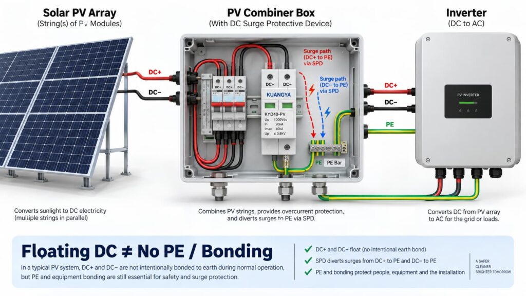
In solar PV systems, the question “can an SPD work without ground?” becomes even more complicated because the DC circuit may be intentionally floating.
Many PV DC circuits operate with neither DC+ nor DC− intentionally bonded directly to earth during normal operation. This is often described as a floating or unearthed DC array.
But that does nicht mean the whole PV installation has no protective earth, bonding or surge path to PE.
A PV SPD may provide coordinated protection between:
Some PV SPDs use a Y-type internal circuit specifically intended for photovoltaic applications. The correct arrangement depends on the inverter topology, PV earthing arrangement, maximum PV voltage, insulation-monitoring concept and the manufacturer’s approved circuit.
This is why a floating PV system can still use a PE-connected SPD arrangement.
IEC 61643-31 applies to SPDs intended for the DC side of photovoltaic installations up to 1500 V DC and covers their performance characteristics, safety requirements, test methods and ratings. See the IEC 61643-31 publication page.
Before selecting a PV SPD, also verify Ucpv, In, Imax, Up and Iscpv. Our Leitfaden für DC-SPD-Spezifikationen explains what these markings mean and why the largest kA number is not enough.
Nein.
A 2P or 3P description does not automatically tell you:
For the same reason, AC module count can also be misleading. If you are comparing neutral/PE arrangements, see our 3+1 vs. 4+0 ÜSS-Vergleich erläutert.
An SPD can be correctly selected and correctly connected to PE, yet still provide poorer installed protection because the connection conductors are too long.
The reason is conductor inductance.
During a fast-rising surge current, additional voltage develops across the SPD connecting conductors:
ΔU = L × di/dt
Wo:
This means the equipment does not necessarily see only the SPD’s datasheet voltage protection level Up. The installed voltage can also include voltage developed across the connection path.
Schneider Electric’s Electrical Installation Guide recommends keeping the total SPD connection length to the network and earth terminal block at no more than approximately 50 cm in the illustrated arrangement and explains the added inductive voltage created by longer conductors. See its SPD connection guidance.
The current consolidated IEC installation standard is IEC 60364-5-53:2019 + Amendment 1:2020 + Amendment 2:2024, which includes Clause 534 for surge protective devices. See the IEC 60364-5-53 consolidated publication page.
If you want a deeper explanation of why conductor length matters during a surge, read our guide on SPD distance from the inverter and connection lead length.
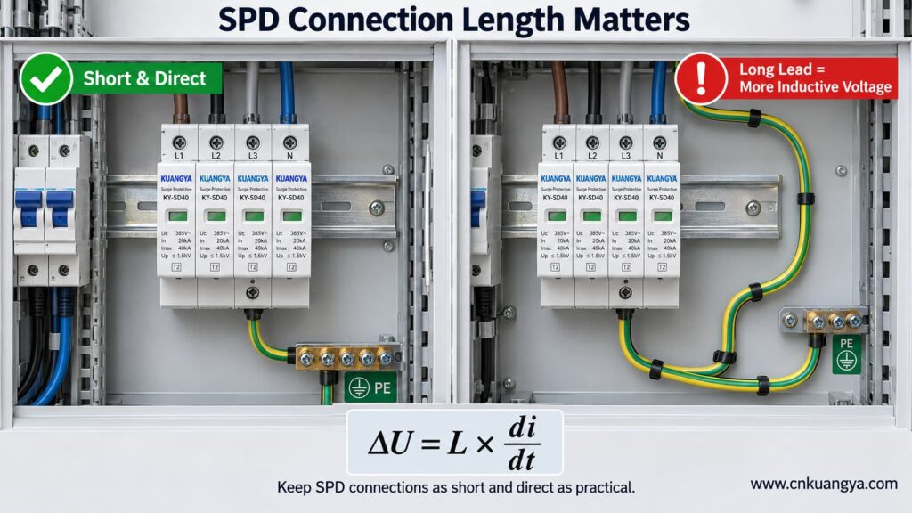
So when asking whether an SPD can work without ground, the quality and length of the PE connection are just as important as whether a protective-earth conductor is physically present.
Trying to reduce lead length by bypassing the approved panel bonding arrangement and connecting an SPD to a separate, isolated earth electrode can create a different problem: the installation may no longer be equipotentially bonded as required.
The correct objective is not “find the nearest piece of earth.”
Sie lautet:
Connect the SPD to the manufacturer-specified PE/bonding point using the shortest practical, low-impedance path permitted by the system design.
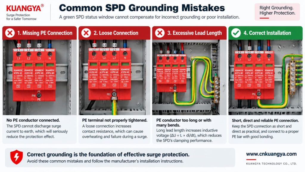
Poor grounding is not one single failure mode. The effect depends on what is actually wrong.
| Problem | Possible Effect | Was ist zu prüfen? |
|---|---|---|
| PE conductor missing | PE-dependent protection modes may not function as intended | Wiring diagram, PE continuity, bonding arrangement |
| Loose PE terminal | Unstable/high-impedance surge path, heating or arcing risk under fault conditions | Terminal condition and specified torque |
| Very long SPD connection | Higher installed residual voltage due to inductive voltage | Lead length and routing |
| Large conductor loop | Higher inductive coupling and loop impedance | Routing and loop area |
| Wrong TN/TT/IT SPD topology | Incorrect protection modes or unsuitable voltage stress | System earthing arrangement and manufacturer approval |
| Unbonded conductive systems | Dangerous transient potential differences may remain | Equipotential bonding of incoming services and installation |
| Green SPD indicator but external wiring fault | False confidence | Inspect the complete installation, not only the indicator |
Not by itself.
This is another important distinction.
A low measured earth-electrode resistance can be useful for the earthing system, but SPD performance during a fast transient also depends heavily on:
Therefore, a long conductor to an excellent earth electrode can still develop significant transient voltage during a steep surge current.
For surge protection, think in terms of impedance and equipotential bonding, not only DC or low-frequency resistance.
Can an SPD work without ground when it only protects L–N? It may limit the voltage between L and N if that is an approved protection mode of the device.
However, three cautions are essential.
If a surge raises both L and N relative to PE, an L–N element may see relatively little differential voltage even though the equipment is experiencing a large common-mode voltage relative to earth.
Electronic equipment can have chassis connections, signal cables, communication ports, antennas, shields or other conductive interfaces that create additional surge paths.
Do not intentionally leave a PE terminal disconnected on an SPD that is designed to use it. The correct wiring diagram is part of the product’s protection concept.
A backup fuse or circuit breaker does not replace grounding.
Likewise, grounding does not replace backup overcurrent protection where the SPD manufacturer requires it.
| Component / Function | Main Role |
|---|---|
| SPD | Limits transient overvoltage and diverts surge current through defined protection modes |
| PE / bonding system | Provides protective bonding and reference/discharge paths according to the installation design |
| Backup fuse or circuit breaker | Helps isolate fault current according to the SPD manufacturer’s coordination requirements |
| Earth electrode | Connects the installation earthing system to earth |
| Voltage protection relay / regulator | Addresses longer-duration abnormal voltage depending on device type |
If you are selecting upstream protection, see our practical guide: does an SPD need a backup fuse or circuit breaker?
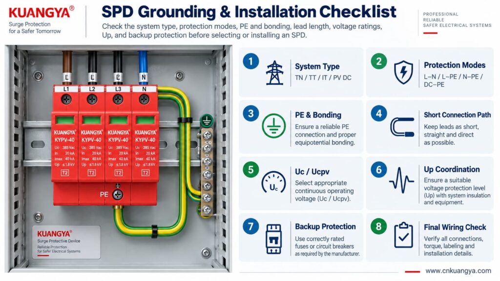
Use the following sequence as a design and inspection checklist. It is not a substitute for local electrical rules or the manufacturer’s instructions.
Confirm whether the circuit is:
Read the internal circuit or wiring diagram, not only the product front label.
Look for protection paths such as L–N, L–PE, N–PE, L1/L2/L3 relationships, DC+–PE and DC−–PE.
Connect only to the approved PE or bonding terminal shown by the manufacturer and installation design.
Avoid unnecessary conductor loops, coils and wide separation between surge-current paths.
For AC, confirm Uc and the applicable system voltage. For PV, confirm Ucpv against the maximum possible PV voltage, including cold-weather Voc where relevant.
Remember that installed protection depends on both the SPD’s Up and the voltage contribution of the connecting conductors.
Verify the manufacturer’s maximum backup fuse / circuit-breaker requirements and the prospective short-circuit conditions.
If an inverter already contains an SPD, do not assume external surge protection is unnecessary. Cable distance, system architecture and the location of the built-in SPD still matter. See our guide on solar inverter built-in SPD and external SPD requirements.
Before deciding whether an SPD can work without ground in a real installation, check the complete protection system rather than judging the SPD alone.
| Siehe | Frage | Warum es wichtig ist |
|---|---|---|
| System | TN, TT, IT, AC or PV DC? | Determines compatible SPD topology |
| Schutzmodi | Which conductor pairs are protected? | Shows what voltage differences the SPD can limit |
| PE-Anschluss | Is PE required and correctly connected? | Essential for PE-dependent protection modes |
| Bonding | Are relevant conductive systems equipotentially bonded? | Reduces dangerous transient potential differences |
| Lead length | Are SPD connections as short and direct as practical? | Reduces added inductive voltage |
| Spannung | Is Uc / Ucpv correct? | Avoids continuous overvoltage stress |
| Protection level | Is Up coordinated with the equipment? | Determines residual voltage stress |
| Surge rating | Are In, Imax and/or Iimp suitable? | Matches expected surge duty |
| Short-circuit conditions | Are SCCR / Iscpv and backup protection suitable? | Important for safe failure and isolation |
| Manufacturer diagram | Does the installed wiring match the approved circuit? | Prevents topology mistakes |
For photovoltaic projects, KUANGYA provides DC-Überspannungsschutzgeräte for different PV voltage classes and installation requirements. Final model selection should always be based on the actual PV voltage, earthing arrangement, protection mode, SPD type and system fault conditions.
Sometimes an individual protection mode such as L–N can operate without a direct PE connection. However, that does not mean the complete surge-protection system can ignore PE, earthing or equipotential bonding. Any SPD mode designed to operate between a live conductor and PE requires the intended PE connection.
When people ask “can an SPD work without ground?”, the answer depends on the SPD circuit rather than on one universal rule. Some devices or protection modes operate only between active conductors, while many power SPDs include PE-related protection modes. Follow the manufacturer’s circuit diagram and select the SPD for the actual TN, TT, IT or DC/PV system.
The SPD may still operate, but a long connection can add inductive voltage during a fast-rising surge current. This can increase the voltage that appears at the protected equipment. Short, direct connections are therefore an important part of SPD installation.
Do not improvise an isolated grounding path simply to make the SPD conductor shorter. The SPD should be connected to the approved PE/bonding point in accordance with the system design, manufacturer instructions and applicable electrical rules.
Not by itself. Surge performance also depends on high-frequency impedance, connection length, conductor routing, loop area, bonding and the SPD’s protection characteristics. A low earth-electrode resistance does not compensate for poor SPD wiring.
Yes. A PV DC system may have neither polarity intentionally grounded during normal operation while still using a properly designed SPD arrangement with protection paths to PE. Use a PV SPD approved for that topology and voltage.
No. A status indicator normally reports the condition of the SPD’s internal monitoring or disconnection mechanism. It does not verify external PE continuity, bonding, conductor length or correct earthing-system selection.
No. An SPD and the installation’s protective-earthing/bonding system perform different functions. A surge protective device should be considered part of a coordinated electrical protection system, not a replacement for protective earthing.
Grounding and bonding are fundamental parts of electrical safety and lightning/surge protection, but they do not perform the same voltage-limiting function as an SPD at equipment terminals. A complete design may require both, depending on the installation.
There is no single standard that answers every installation question. IEC 61643-11 covers AC low-voltage SPD product requirements, IEC 61643-31 covers PV DC SPD product requirements, and IEC 60364-5-53 includes installation requirements for low-voltage electrical installations, including Clause 534 for SPDs. Project-specific lightning-protection and national wiring requirements may also apply.
Kann ein Überspannungsschutzgerät (SPD) ohne Erdung funktionieren? The answer cannot be reduced to a simple yes or no.
An SPD limits voltage across specific protection modes. A mode between active conductors, such as L–N, may operate without directly using PE. But any protection mode that depends on L–PE, N–PE, DC+–PE or DC−–PE requires the designed PE/bonding path.
More importantly, surge protection is a system function.
A correctly selected SPD can still perform poorly if:
For that reason, do not ask only:
“Does this SPD have a ground terminal?”
Ask instead:
“What voltage differences must be limited, what protection modes does this SPD provide, and how is the complete system bonded and earthed?”
That question leads to a much safer and more technically correct SPD selection.
Technical note: This article is intended for product selection and engineering education. Actual SPD installation must follow the device manufacturer’s wiring instructions, the applicable electrical installation standard, and local code requirements.

