WengYang Industriegebiet Yueqing Wenzhou 325000
Arbeitszeiten
Montag bis Freitag: 7AM - 7PM
Am Wochenende: 10AM - 5PM
WengYang Industriegebiet Yueqing Wenzhou 325000
Arbeitszeiten
Montag bis Freitag: 7AM - 7PM
Am Wochenende: 10AM - 5PM

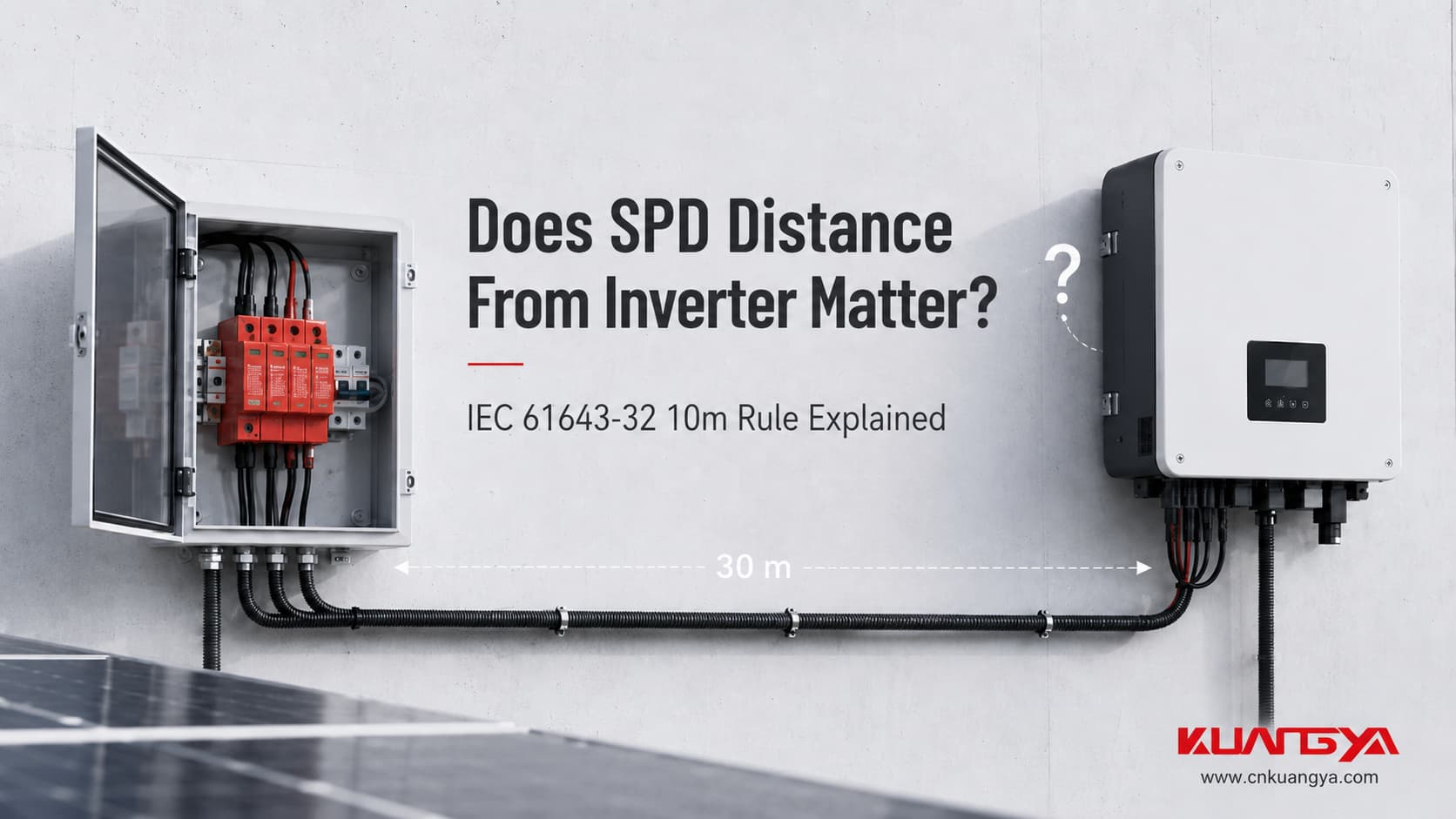
Der Abstand des SPD zum Wechselrichter ist ein wichtiger Bestandteil der Auslegung des Überspannungsschutzes für Photovoltaikanlagen, insbesondere wenn das SPD in einem Generatoranschlusskasten oder in der Nähe des PV-Generators installiert ist.
Sie haben ein DC-Überspannungsschutzgerät in der PV-Anlage installiert, aber das SPD befindet sich im Generatoranschlusskasten, während der Wechselrichter 20 oder 30 Meter entfernt ist.
Daraus ergibt sich eine sehr praktische Frage:
Reicht dieses SPD noch aus, um den Wechselrichter zu schützen?
Oder sollte ein weiteres SPD näher am Wechselrichter installiert werden?
Die Antwort lautet:
Ja, der Abstand spielt eine Rolle.
In einer Photovoltaikanlage wird der Überspannungsschutz nicht allein dadurch bestimmt, ob irgendwo im Gleichstromkreis ein SPD vorhanden ist. Der Abstand zwischen dem PV-Generator und dem Wechselrichter, der Installationsort des SPD, die Länge der Anschlussleitungen des SPD, die Stoßspannungsfestigkeit der Betriebsmittel sowie das Blitzschutzkonzept beeinflussen das endgültige Schutzkonzept.
IEC 61643-32 befasst sich spezifisch mit der Auswahl, Installation und Koordination von SPDs in Photovoltaikanlagen bis 1.500 V DC. Es unterscheidet zwischen kurzen und langen Abständen zwischen den PV-Modulen und dem Wechselrichter und stellt spezifische Anforderungen an die Platzierung des SPD.
Die richtige Frage lautet also nicht einfach:
“Habe ich bereits ein SPD?”
Sie lautet:
“Ist das SPD am richtigen Ort installiert, um die Geräte zu schützen, die mir wichtig sind?”
Für PV-Anlagen, die unter die entsprechenden Konfigurationen der IEC 61643-32 fallen:
Verwechseln Sie dies gleichzeitig nicht mit diesem 10-m-Systemabstand mit der ungefähren Empfehlung für 0,5 m SPD-Anschlussleitungen.
Sie beschreiben zwei verschiedene elektrische Probleme.
| Frage | Praxisorientierte Antwort |
|---|---|
| Spielt der Abstand zwischen PV-Anlage und Wechselrichter eine Rolle? | Ja |
| Ist 10 m eine willkürliche Marketing-Regel? | Nein. Sie erscheint explizit in der IEC 61643-32 |
| Bedeutet ≥10 m immer das Gleiche in jedem Land und bei jeder Installation? | Nein. Die geltende Norm, die LPS-Bedingungen, nationale Vorschriften und die Systemkonfiguration sind weiterhin maßgeblich. |
| Sind 0,5 m der maximale Abstand zwischen dem SPD und dem Wechselrichter? | Nein |
| Worauf beziehen sich die 0,5 m? | Die SPD-Anschlussleitungen in der entsprechenden Verdrahtungskonfiguration. |
| Kann ein integrierter Wechselrichter-SPD Teil der zweiten Schutzstufe sein? | Möglicherweise, sofern dessen Spezifikation und Installation die erforderliche Schutzfunktion erfüllen. |
| Kann ein größerer Imax eine schlechte Platzierung des SPD kompensieren? | Nein |
| Sagt der Up-Wert allein aus, welcher Spannung der Wechselrichter ausgesetzt sein wird? | Nein. Die Installationsverdrahtung trägt bei einem Überspannungsereignis ebenfalls zur Spannung bei. |
Ein häufiges Missverständnis ist, dass Kupferkabel bei einem Überspannungsereignis elektrisch vernachlässigbar seien.
Bei normaler Betriebsfrequenz oder konstantem Gleichstrom mag diese Annahme plausibel erscheinen.
Ein blitzbedingter Stoßstrom ist jedoch anders.
Stoßströme ändern sich extrem schnell. Jeder Leiter besitzt eine Induktivität, und wenn sich der Strom schnell durch diese Induktivität ändert, baut sich über dem Leiter eine Spannung auf.
Der grundlegende Zusammenhang lautet:
Wo:
ΔU = zusätzliche induktive Spannung über dem Leiter
L = Leiterinduktivität
di/dt = Änderungsrate des Stoßstroms
Diese Gleichung ist nicht auf den Überspannungsschutz beschränkt. Es handelt sich um einen grundlegenden elektromagnetischen Zusammenhang.
Für die Installation von SPD-Geräten verdeutlicht sie jedoch etwas sehr Wichtiges:
Der an das SPD angeschlossene Leiter wird Teil des Überspannungsschutz-Stromkreises.
Die Installationsanleitung für Überspannungsschutz von Phoenix Contact liefert ein anschauliches Beispiel unter Verwendung von ca. 1 µH/m Leiterinduktivität. Bei einer Stromänderung von 10 kA über 10 µs können über einem Meter Leiter ca. 1 kV entstehen. Dies ist eher eine Veranschaulichung als ein universeller Auslegungswert, da die tatsächliche Induktivität von der Leitergeometrie und der Leitungsführung abhängt.
Deshalb betonen SPD-Hersteller immer wieder kurze, direkte Verbindungen.
Angenommen, ein Datenblatt für einen Überspannungsschutz (SPD) gibt Folgendes an:
Spannungsschutzpegel Up = 2,5 kV
Eine gängige Interpretation lautet:
“Wenn dieser SPD anspricht, wird der Wechselrichter nicht mehr als 2,5 kV sehen.”
Das ist zu einfach ausgedrückt.
Nach oben Der Spannungsschutzpegel des SPD wird unter festgelegten Prüfbedingungen bestimmt.
Sobald der SPD in einem realen elektrischen System installiert ist, muss auch die Spannung berücksichtigt werden, die über seinen Anschlussleitungen abfällt.
Eine vereinfachte Betrachtungsweise des installierten Schutzpegels ist:
Effektive Spannung am geschützten Gerät ≈ SPD Up + Spannungsbeitrag der Anschlussleitungen
Schneider Electric veranschaulicht diesen Zusammenhang mithilfe der Induktivitätsgleichung für Leiter und beschreibt das installierte Schutzniveau als SPD Up zuzüglich der in den Anschlüssen entstehenden Spannung.
Das bedeutet nicht, dass man einfach einen festen Wert zu jedem SPD-Datenblatt addieren sollte.
Der tatsächliche Wert hängt ab von:
Die praktische Lehre ist viel einfacher:
Ein guter Überspannungsschutz (SPD) mit schlechter Verdrahtung kann einen schlechteren Schutz bieten, als es das Datenblatt vermuten lässt.
Wenn Sie nicht vertraut sind mit Ucpv, In, Imax, Up und Iscpv, lesen Sie unseren Leitfaden zu Wie man ein DC-SPD-Etikett liest vor der Bewertung der SPD-Platzierung.
Diese Unterscheidung ist entscheidend, da der Abstand des SPD zum Wechselrichter oft mit der Länge der eigenen Anschlussleitungen des SPD verwechselt wird.
Oft sagen Leute:
“Das SPD muss nah dran sein.”
Aber “nah” kann sich auf zwei völlig unterschiedliche Abstände beziehen.
Betrachten Sie diese Anordnung:
PV-Generator → Generatoranschlusskasten + SPD → 30 m DC-Kabel → Wechselrichter
Die Frage ist hier, ob der an einem Ende des langen Kabels bereitgestellte Schutz für die Geräte am anderen Ende ausreicht.
Dies ist ein Problem der SPD-Platzierung und -Koordination auf Systemebene.
Hier wird die 10-m-Vorgabe der IEC 61643-32 relevant.
Stellen Sie sich nun vor:
DC Cable → SPD → PE / Bonding Point
The SPD may be installed physically beside the inverter, but its connecting wires may be long and looped around the enclosure.
That is a different problem.
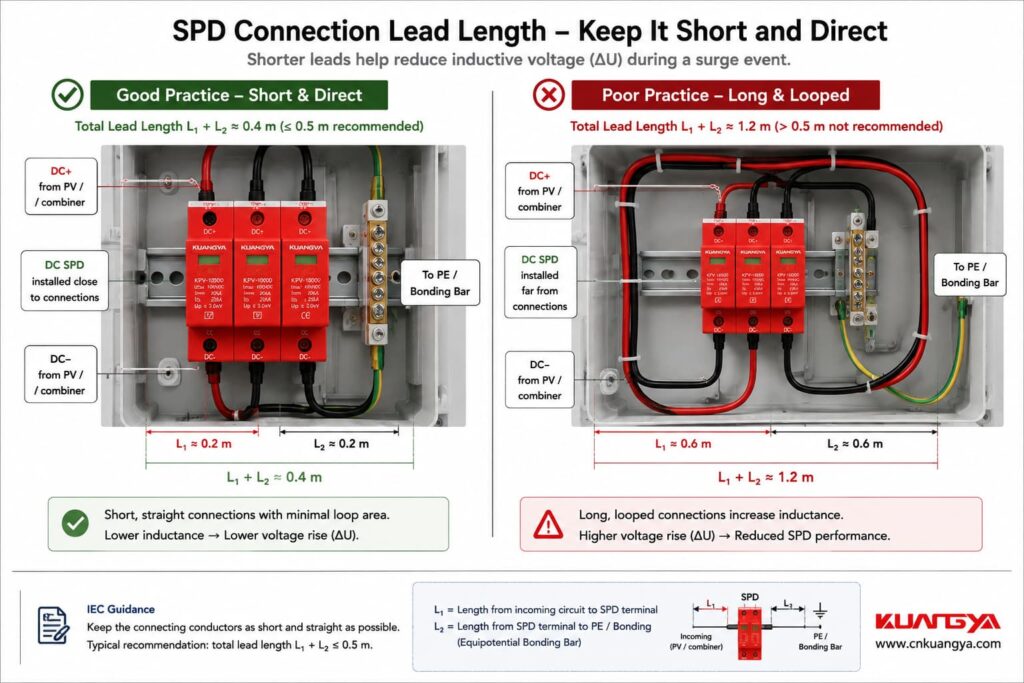
IEC 61643-32 states for the DC-side arrangement in Clause 9.2.5 that the total length of the relevant connecting cables, shown as L1 + L2, should be as short as possible and preferably should not exceed 0.5 m total lead length.
Also:
10 m ≠ 0.5 m

The first concerns the distance between protected parts of the PV system.
The second concerns the SPD’s own electrical connection.
Mixing these two numbers produces a lot of incorrect SPD advice online.
When engineers discuss der Abstand des SPD zum Wechselrichter in a PV system, the 10 m value is one of the most important distances to understand.
IEC 61643-32:2017 Clause 9.2.5 addresses installation of SPDs on the DC side.
For PV installations described in 6.2.1 und 6.2.2, it states that when distance E between the PV modules and inverter is equal to or greater than 10 m, two sets of SPDs are necessary to sufficiently protect both the PV modules and inverter.
When the distance between the protected units is weniger als 10 m, one set of SPDs may be enough. The standard also notes that, for common PV modules, the inverter normally has the lower rated impulse withstand voltage, so installation of the SPD close to the inverter is recommended.
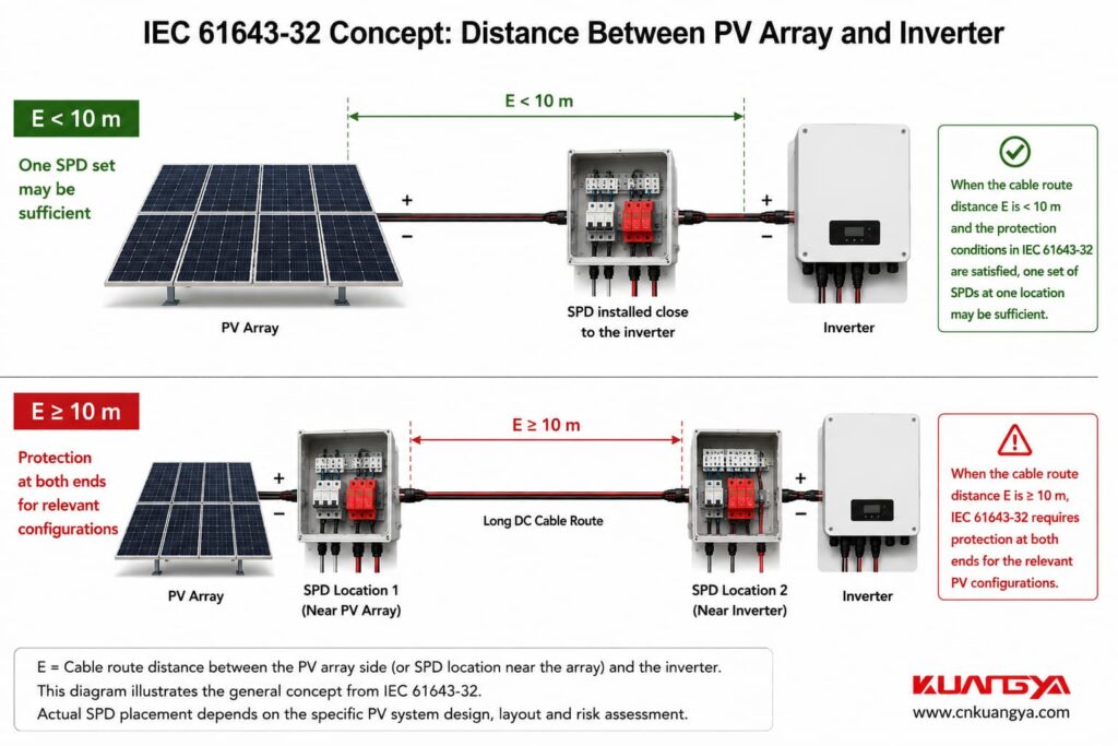
This means that the often-mentioned “10-meter rule” is not simply an industry habit.
It has a specific basis in IEC 61643-32.
However, it should not be transformed into an oversimplified statement such as:
“Every solar installation anywhere in the world automatically requires two SPDs once the cable reaches exactly 10 meters.”
That is also incorrect.
IEC 61643-32 defines specific PV configurations, and national adoption, local installation standards, equipment instructions, risk assessment, and lightning protection conditions still have to be considered.
The context matters.
IEC 61643-32 separates common PV installations into several arrangements.
This is the configuration described in Clause 6.2.1.
In general, IEC illustrates protection at both the inverter side and PV-array side, but it allows one of the DC SPDs to be omitted under specified conditions.
For example, where the distance between inverter and PV array is less than 10 m and the voltage protection level of the remaining SPD is sufficiently coordinated with the PV array impulse withstand voltage, the additional SPD may not be necessary.
Clause 6.2.2 addresses a building with an external lightning protection system where the required separation distance between the LPS and PV installation is maintained.
Again, IEC generally shows protection at both ends but permits omission under specified conditions.
The DC-side 10 m principle in Clause 9.2.5 applies to this configuration as well.
This is a more severe condition.
When the required separation distance cannot be maintained, conductive PV components may become part of the lightning-current path.
IEC 61643-32 specifies Class I tested SPDs at the relevant locations for this configuration, and Clause 9.2.5 notes that the second SPD at the inverter is mandatory for the case described in 6.2.3.
If the difference between Class I, Class II and the commonly used Type 1, Type 2 and Type 1+2 terminology is unclear, see our guide to DC SPD classes and types.
Daher:
Do not use distance alone to decide the SPD Type when an external lightning protection system is involved.
The LPS design and separation distance must be evaluated first.
This sentence is important.
IEC does nicht say:
“If the PV cable is 9 meters long, one SPD is always enough.”
It says one set may be enough.
Warum?
Because distance is only one factor.
The SPD voltage protection level still has to be coordinated with the impulse withstand voltage of the equipment being protected.
IEC uses:
Uw = rated impulse withstand voltage of the equipment
und
Nach oben = voltage protection level of the SPD.
For effective equipment protection, IEC 61643-32 states that Up must be lower than Uw and generally recommends maintaining at least a 20% safety margin:
subject to the applicable exceptions and coordination conditions.
So a short cable does not excuse poor SPD selection.
The SPD still has to be electrically suitable for the equipment.
For a broader selection workflow covering voltage rating, Up, discharge-current ratings and installation conditions, see wie ein DC-Überspannungsschutz für eine Photovoltaikanlage zu dimensionieren ist.
Consider two systems using exactly the same Type 2 DC SPD.
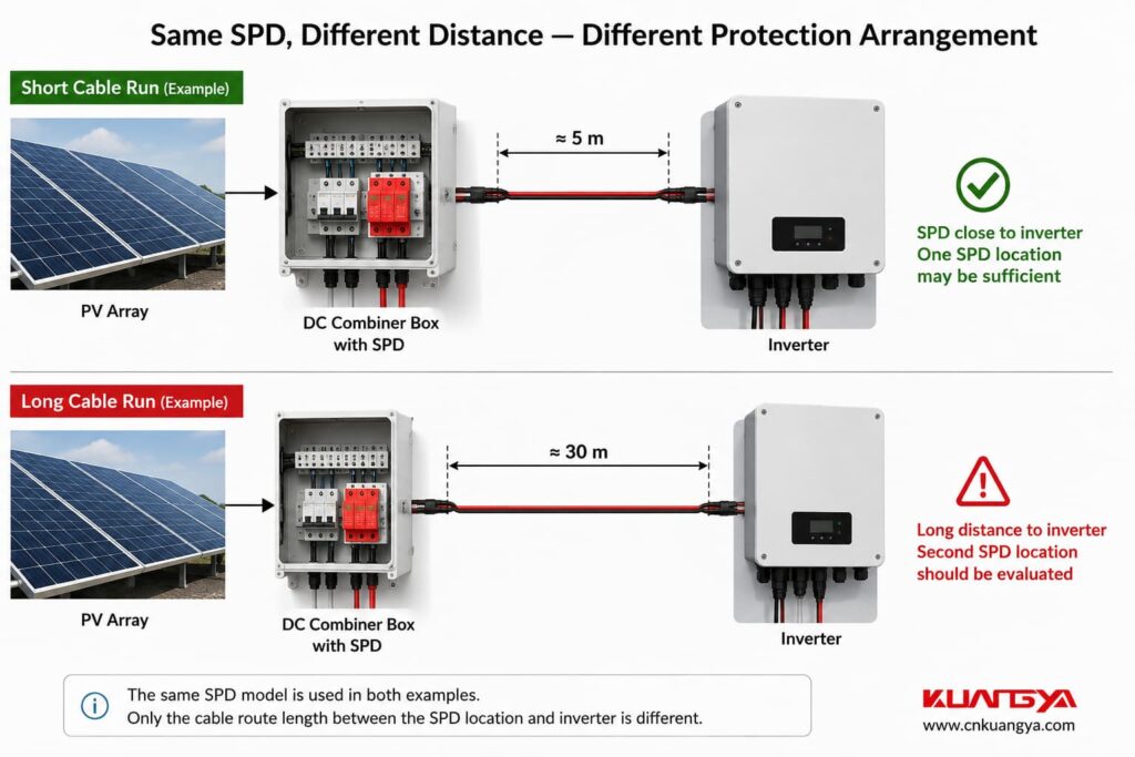
PV Array → 5 m DC Cable → SPD → Inverter
The SPD is close to the inverter.
PV Array → SPD → 30 m DC Cable → Inverter
Both systems contain one SPD.
But they should not automatically be treated as equivalent protection designs.
For the relevant IEC configurations, System B crosses the 10 m distance described in Clause 9.2.5, meaning protection at both ends must be considered according to the standard requirement.
The arrangement would typically become:
PV Array → SPD 1 → 30 m DC Cable → SPD 2 → Inverter
The exact SPD test class and ratings depend on the lightning protection condition and installation design.
Der wichtige Punkt ist:
One SPD located somewhere on a long PV cable does not automatically provide sufficient coordinated protection at both ends.
In this situation, der Abstand des SPD zum Wechselrichter becomes particularly important because the protection device may be located at one end of a long DC cable.
This is one of the most common real-world situations.
A commercial PV system may look like:
PV-Strings
↓
PV-Kombinator-Box
↓
Long DC Cable
↓
Wechselrichter
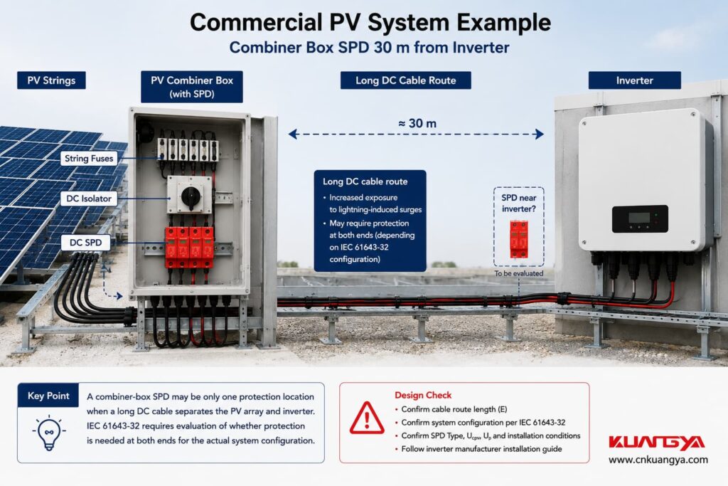
An installer opens the combiner box and sees a Type 2 SPD.
The natural question is:
“Why would I need another SPD? There is already one here.”
If the inverter is only a short distance away, the existing arrangement may satisfy the applicable protection requirements.
But if the cable route between the PV generator and inverter reaches the distance defined by IEC 61643-32, protection at both ends becomes relevant.
Phoenix Contact’s current PV application guidance follows the same basic arrangement: it identifies DC surge protection near the PV panels and DC protection near the inverter and specifically uses 10 m as the cable-distance criterion for the inverter-side location.
So the combiner-box SPD is not “wrong.”
It may simply represent only one protection location within a larger surge-protection concept.
Now the situation becomes more interesting.
Suppose the system is:
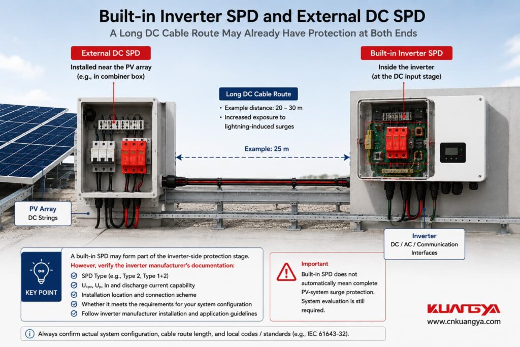
PV Array → External SPD → 25 m DC Cable → Inverter with Built-In Type 2 SPD
Potentially, you already have protection at both ends.
But you cannot confirm that from the words:
“Built-in SPD”
alone.
You need to check what is actually inside the inverter.
Important questions include:
A built-in SPD may form part of the inverter-side protection stage.
But:
Built-in SPD does not automatically mean complete PV-system surge protection.
If this is the situation in your system, read My Solar Inverter Already Has an SPD — Do I Still Need an External SPD? for a detailed explanation of when built-in and external protection may need to work together.
This is why SPD location and inverter documentation must be considered together.
Use this SPD distance from inverter checker to make a preliminary assessment of whether surge protection may be needed at both ends of a PV DC cable.
Now return to the second distance problem.
Even if your SPD is installed at exactly the correct system location, its wiring can still reduce protection performance.
Bedenken Sie:
DC conductor → short connection → SPD → short PE connection
und:
DC conductor → long loop → SPD → long loop → PE
The SPD model is identical.
Its datasheet Up is identical.
Its Imax is identical.
But the installed protection can be different.
Phoenix Contact explains that excessive SPD connection length raises the effective voltage protection level because of voltage developed across the conductor inductance. Its installation guidance references the 0.5 m connection-length principle and shows how conductor voltage has to be added to the SPD protection level when evaluating the complete installed protection.
IEC 61643-32 gives the same practical message for the DC side:
keep the SPD connecting cables as short as possible.
The 0.5 m figure should therefore be treated as a wiring target, not as a reason to mount an SPD exactly 500 mm from the inverter.
Enter the total relevant SPD connection lead length to check whether the wiring should be reviewed.
This is a practical installation check, not a pass/fail safety certification. The applicable wiring arrangement, relevant standards, and manufacturer instructions must also be considered.
Suppose we use a simplified conductor inductance of:
L ≈ 1 µH/m
and a surge-current rise of:
10 kA in 10 µs
Then:
di/dt = 1 kA/µs
For one meter:
ΔU = L × di/dt
ΔU ≈ 1 µH × 1 kA/µs
ΔU ≈ 1 kV
This is the type of example Phoenix Contact uses to demonstrate why lead length matters.
But this should nicht be turned into a calculator that claims:
“Every meter always adds exactly 1 kV.”
It does not.
Real values change with:
The calculation is best used to explain the physics, not to produce false precision.
Nein.
Suppose one SPD has:
Imax = 40 kA
and another:
Imax = 80 kA
It is tempting to think:
“If my SPD is far from the inverter, I will simply install the 80 kA model.”
That does not solve the placement problem.
Imax describes the maximum discharge-current capability under the specified 8/20 µs test conditions.
It does not eliminate:
A higher Imax may be appropriate for some installations, but it is not a substitute for correct SPD placement.
Again, not by itself.
A lower Up can improve equipment protection because it means the SPD limits voltage to a lower level under its specified test conditions.
But the final installed protection depends on the complete circuit.
Zum Beispiel:
Up = 2.0 kV
Very long connecting conductors
Up = 2.5 kV
Very short, direct connections
You cannot determine which installation produces the lower voltage at the equipment terminals from the SPD label alone.
The conductor voltage contribution also matters.
That is why SPD selection and SPD installation should never be treated as separate topics.
The physical cable route matters too.
Cable length is an easy number to measure, but electromagnetic behavior is influenced by geometry.
For surge currents, good practice includes:
IEC 61643-32 itself emphasizes minimizing loop areas in DC-side installation diagrams and recommends direct earthing between SPD and inverter for optimum overvoltage protection.
So two systems with the same “10 m cable length” are not necessarily electromagnetically identical.
An inverter is connected to more than one electrical system.
It has a DC input from the PV array and an AC connection to the distribution system.
IEC 61643-32 also addresses the AC side of the PV installation.
For the AC side, it recommends that where the wiring between the SPD near the origin of the electrical installation and the inverter is 10 m oder mehr beträgt, the inverter should be protected by an additional SPD adjacent to the inverter.
For the more severe external-LPS configuration described in Clause 6.2.3, the additional SPD at the inverter is mandatory.
Phoenix Contact’s current selection guidance follows the same basic structure, showing an additional AC-side SPD near the inverter when the cable length to the main distribution is 10 m or more.
Daher:
A DC SPD does not replace AC surge protection.
Both electrical interfaces need to be assessed.
SPD placement is only one part of the overall protection architecture. For the relationship between SPDs, gPV fuses, DC isolators, combiner boxes and inverter protection, see our complete solar PV electrical protection guide.
Modern PV inverters may also be connected to:
These conductors can provide another path for transient overvoltages.
IEC 61643-32 states that when SPDs are required for the power circuits, surge protection should also be considered for telecommunications and signalling circuits associated with the PV system. Phoenix Contact makes the same practical recommendation for common inverter interfaces such as Ethernet and RS-485.
So an engineer reviewing inverter surge protection should ask:
“What conductors enter the inverter?”
not only:
“Where is the DC SPD?”
This is where simplified internet advice becomes especially risky.
If a building has an external lightning protection system (LPS), first determine whether the required separation distance s between the lightning protection system and the PV installation is maintained.
For the IEC configuration where the external LPS exists but separation distance is maintained, Class II tested PV SPDs are used at the relevant DC locations in the arrangement described by IEC 61643-32.
The 10 m DC-side placement principle still applies to the configuration covered by 6.2.2.
If separation distance cannot be maintained, parts of the PV system can carry partial lightning current.
This changes the required protection concept.
IEC 61643-32 specifies Class I tested SPDs at the relevant locations for this configuration, and the protection arrangement becomes more stringent.
This is why you should never decide:
“Type 2 is enough because the cable is only 8 meters.”
without first knowing the lightning protection condition.
Distance is only one part of the design.
PV Array → 6 m DC Cable → Inverter
No external LPS.
A suitable SPD is installed close to the inverter.
In this case, one set of DC SPDs may be sufficient if the applicable IEC conditions, Up coordination, equipment withstand voltage, and manufacturer instructions are satisfied.
The fact that the distance is below 10 m helps, but it is not the only requirement.
PV Array → Combiner Box + SPD → 25 m DC Cable → Inverter
For the relevant IEC 61643-32 configurations, the distance is ≥10 m.
Protection should therefore be provided at both ends in accordance with the standard arrangement.
A second suitable SPD close to the inverter is required for the configurations addressed by Clause 9.2.5.
PV Array → External SPD → 25 m DC Cable → Built-In SPD → Inverter
This may already resemble a two-location protection concept.
But the built-in device must be checked against:
Do not remove the external SPD simply because the inverter datasheet says “SPD included.”
PV Array → Inverter Cabinet
Inside the cabinet:
DC terminal → 80 cm wire → SPD → 70 cm PE wire
The system-level location may be good.
The SPD wiring is not.
The long connecting conductors can increase the installed protection level because of their inductive voltage.
In this case, the first fix is not necessarily another SPD.
It may be to redesign the connection.
Now cable distance alone is no longer the main issue.
The system has to account for partial lightning current, lightning equipotential bonding, SPD test class, and the complete LPS design.
This requires a lightning-protection-based SPD design rather than a simple “less than or greater than 10 m” decision.
| Situation | What IEC-Based Design Tells You to Check |
|---|---|
| PV array to inverter <10 m | One set may be sufficient, subject to protection-level conditions |
| PV array to inverter ≥10 m | Two sets necessary for relevant IEC 61643-32 configurations |
| External LPS, separation maintained | Apply the relevant 6.2.2 SPD arrangement |
| External LPS, separation not maintained | More stringent Class I/lightning-current protection applies |
| SPD leads approaching or exceeding 0.5 m | Review connection layout and installed protection level |
| SPD close to inverter | Still check Up, Ucpv, wiring, bonding and coordination |
| Inverter built-in SPD | Verify whether it satisfies the required inverter-side protection function |
| Long AC cable to main distribution | Additional AC-side SPD near inverter may be required/recommended |
| Communication lines entering inverter | Evaluate surge protection for signalling/data circuits |
An SPD protects according to its location, installation, and coordination with the rest of the system.
A device installed at one end of a long conductor should not automatically be assumed to provide the same protection at the other end.
Nein.
The 10 m distinction appears directly in IEC 61643-32.
For the relevant DC-side configurations, ≥10 m leads to a two-SPD requirement for sufficient protection of both PV modules and inverter.
Also incorrect.
Below 10 m, IEC says one set may be sufficient.
Protection-level coordination and the rest of the installation still matter.
Nein.
The 0.5 m guidance refers to the SPD’s relevant connecting conductors.
It is not the same measurement as the PV-array-to-inverter distance.
Nein.
Imax does not compensate for long conductors, poor bonding, or incorrect protection location.
Not automatically.
Built-in protection has to be evaluated as part of the full PV protection concept.
The inverter also connects to AC and often to communication lines.
All possible surge-entry paths should be reviewed.
Before deciding that one SPD is enough, check:
Only after these points are understood should the designer decide whether an additional SPD is unnecessary, recommended, or required.
Ja.
The physical distance between protected parts of the PV system is specifically considered in IEC 61643-32, and long SPD connection leads can also increase the effective installed protection level.
These are two separate effects.
For PV installations covered by IEC 61643-32 Clauses 6.2.1 and 6.2.2, when the cable-route distance E between PV modules and inverter is equal to or greater than 10 m, Clause 9.2.5 requires two sets of SPDs to sufficiently protect both ends.
The exact SPD class and ratings still depend on the system and lightning protection arrangement.
Nein.
IEC states that one set may be enough below 10 m.
The SPD voltage protection level, equipment impulse withstand voltage, installation arrangement, and other conditions still need to be satisfied.
IEC notes that common PV modules generally have a higher rated impulse withstand voltage than the inverter, and therefore recommends installing the SPD close to the inverter when one set is used.
For practical application, the relevant distance is the electrical cable-route distance between the units, not simply the straight-line distance measured through the air.
Nein.
For the DC-side arrangement in IEC 61643-32 Clause 9.2.5, the 0.5 m recommendation refers to the total relevant SPD connecting leads, identified as L1 + L2 in the standard example.
Because the connecting conductors have inductance.
During a fast-rising surge current, the conductor develops an additional voltage:
ΔU = L × di/dt
This additional voltage contributes to the installed voltage appearing at the protected equipment.
Potentially, yes.
But its Type/test class, Ucpv, Up, protected circuit arrangement, installation, and manufacturer requirements must first be verified.
Do not assume all built-in SPDs are equivalent.
Nein.
DC and AC are separate surge paths.
The AC-side protection arrangement must be evaluated separately.
First determine whether the required separation distance between the external LPS and PV installation is maintained.
If it is not maintained, IEC 61643-32 applies a more stringent lightning-current protection arrangement using Class I tested SPDs at the relevant locations.
Yes. SPD distance from inverter matters in solar PV surge protection design.
But there are two different distances that must not be confused.
The first is:
the cable-route distance between the PV array and inverter.
For the relevant IEC 61643-32 configurations:
E < 10 m
→ one set of SPDs may be sufficient if the required protection conditions are met.
E ≥ 10 m
→ two sets of SPDs are necessary to sufficiently protect both PV modules and inverter.
The second distance is:
the length of the SPD’s own connecting conductors.
These conductors should be kept as short as possible, with IEC 61643-32 giving a preferred total lead length of no more than approximately 0.5 m for the DC-side arrangement shown in Clause 9.2.5.
Neither rule should be used alone.
A technically sound PV surge-protection design also considers:
Up, Uw, Ucpv, SPD test class, lightning protection system, separation distance, bonding, earthing, cable routing, inverter built-in protection, AC-side protection, and SPD coordination.
The useful question is therefore not:
“How many SPDs does my solar system have?”
Sie lautet:
“Are the SPDs positioned, selected, and connected so that every vulnerable part of the system receives the required protection?”
That is the difference between simply installing an SPD and designing a coordinated surge-protection system.
If you are unsure whether the existing SPD is far enough from the inverter to require another protection stage, send us:
KUANGYA can help you identify the SPD parameters and installation positions that should be checked before product selection.
You can also view our DC surge protective devices for solar PV systems for available Type 2 and Type 1+2 DC SPD options.
KUANGYA — Surge Protection for Solar PV Systems

