웽양 공업구 웨칭 원저우 325000
근무 시간
월요일~금요일: 오전 7시~오후 7시
주말: 주말: 오전 10시 - 오후 5시
웽양 공업구 웨칭 원저우 325000
근무 시간
월요일~금요일: 오전 7시~오후 7시
주말: 주말: 오전 10시 - 오후 5시

SPD가 접지 없이 작동할 수 있습니까? 기술적으로 정확한 답변은 다음과 같습니다. 때때로 특정 보호 모드는 직접적인 PE 경로 없이도 작동할 수 있지만, 그렇다고 해서 접지나 본딩 없이 서지 보호 시스템 전체가 올바르게 보호된다는 의미는 아닙니다.
서지 보호 장치는 단순히 “모든 서지를 땅으로 보내는” 것이 아닙니다. 보호 모드 양단의 전압이 동작 범위를 초과할 때 전도성을 띠게 함으로써 정의된 도체 간의 전압을 제한합니다. SPD 설계에 따라 이러한 보호 모드에는 선간-중성선(L–N), 선간-보호접지(L–PE), 중성선-보호접지(N–PE) 또는 DC+/DC− 대 PE가 포함될 수 있습니다.
이것이 바로 이 질문이 “접지 여부”보다 더 복잡한 이유입니다. 실제 엔지니어링 관점에서의 질문은 다음과 같습니다.
해결하려는 문제가 접지가 아니라 과도 서지와 장시간 전압 문제 사이의 차이점이라면, 먼저 다음을 읽어보십시오. SPD가 과전압으로부터 보호합니까?. 접지는 SPD를 전압 조정기나 일반 과전압 계전기로 바꿀 수 없습니다.
SPD가 접지 없이 작동할 수 있습니까? 더 나은 답변은 다음과 같습니다: 이는 “접지”의 의미와 논의 중인 SPD 보호 모드가 무엇인지에 따라 다릅니다.
| 상황 | SPD가 여전히 어떤 역할을 할 수 있습니까? | 주요 우려 사항 |
|---|---|---|
| 해당 모드에서 직접적인 PE 연결이 없는 L–N 보호 모드 | 잠재적으로 가능함 | L과 N 사이의 차동 모드 전압만 제한됨 |
| PE가 누락된 L–PE 또는 N–PE 보호 모드 | 의도한 바와 다름 | 설계된 보호 경로가 불완전하거나 부정확함 |
| PE는 존재하나 연결 길이가 지나치게 김 | SPD가 여전히 작동할 수 있음 | 추가적인 유도 전압이 설치된 보호 수준을 높일 수 있음 |
| TN/TT/IT 접지 시스템에 부적합한 SPD | 올바른 보호가 이루어질 것이라고 가정하지 말 것 | 보호 모드, TOV 스트레스 및 고장 조건이 시스템과 일치하지 않을 수 있음 |
| 수상 태양광 DC 시스템 | 네, 올바르게 설계된 PV SPD 구성이 있다면 가능합니다 | “플로팅 DC”라고 해서 PE 및 등전위 본딩을 무시할 수 있다는 의미는 아닙니다 |
| 효과적인 본딩이 없거나 PE 연결이 손상된 경우 | 보호 기능이 심각하게 저하될 수 있습니다 | 도전성 시스템 간에 전위차가 잔류할 수 있습니다 |
가장 중요한 규칙은 다음과 같습니다:
모듈 수만 보고 SPD에 “접지가 필요한지” 결정하지 마십시오. 시스템 접지 방식과 SPD의 실제 보호 모드를 확인하십시오.
이것이 바로 2P 또는 3P PV SPD를 외관만 보고 선택해서는 안 되는 이유입니다. 당사의 2P 대 3P DC SPD 가이드 는 모듈 수, 보호 도체, PE 연결 및 내부 보호 경로가 왜 서로 다른 개념인지 설명합니다.
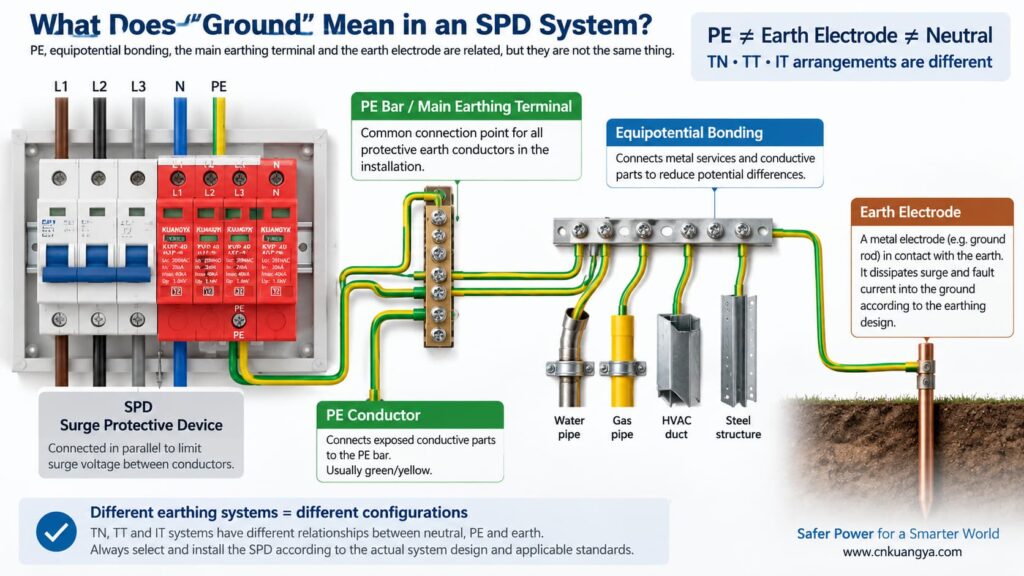
“SPD가 접지 없이 작동할 수 있는가?”라는 질문에 답하기 전에, 먼저 전기 설비에서 “접지”가 실제로 무엇을 의미하는지 정의해야 합니다.
일상적인 대화에서 “접지”는 여러 가지 다른 의미를 지칭할 수 있습니다.
PE는 노출된 도전부와 전기 설비의 보호 본딩 시스템을 연결하는 데 사용되는 보호 도체입니다. 많은 전원 SPD는 PE를 기준으로 하는 보호 모드를 포함합니다.
이는 시스템 설계에 따라 보호 도체가 연결되는 설치 또는 배전반 내부의 본딩 지점입니다.
접지 전극은 전기 설비와 대지 사이에 도전성 연결을 제공합니다. 이는 접지 시스템의 일부이지만, SPD와 로컬 PE 바 사이의 짧은 PE 연결과 혼동해서는 안 됩니다.
본딩은 도전성 부품과 설비 간의 위험한 전위차를 줄여줍니다. 서지 발생 시, 서지 전류가 단순히 “접지선을 타고 내려간다”고 생각하는 것보다 전위차를 제어하는 것이 훨씬 중요합니다.”
중성선과 접지의 관계는 접지 시스템에 따라 다릅니다. TN, TT, IT 시스템은 동일한 중성선/PE 구성을 사용하지 않으며, 이것이 동일한 SPD 토폴로지가 모든 곳에 적합하다고 가정해서는 안 되는 이유 중 하나입니다.
ABB의 실무 SPD 지침은 공급 중성선과 장비 접지가 어떻게 연결되어 있는지에 따라 TT, TN-C, TN-S 및 IT 접지 시스템을 구분합니다. 따라서 SPD 선정은 보편적인 “접지선” 규칙에 기반하기보다 실제 전기 시스템과 조화를 이루어야 합니다.
일반적인 전원용 SPD는 회로에 직렬로 연결되어 정상 부하 전류를 전달하는 대신 병렬로 연결됩니다. 정상 상태에서 서지 보호 소자는 고임피던스 상태를 유지합니다. 보호 모드의 전압이 충분히 상승하면 SPD는 도통 상태가 되어 해당 보호 경로로 서지 전류를 우회시킴으로써 전압을 제한합니다.
회로 수준의 설명을 먼저 확인하려면 다음을 참조하십시오. SPD가 직렬이 아닌 병렬로 연결되는 이유.
"과전압 보호"라는 문구는 “서지 전류를 접지로 우회(divert surge current to ground)” 이는 단순화된 설명으로는 유용하지만 오해를 불러일으킬 수도 있습니다. 모든 서지가 접지봉으로 직접 연결된 하나의 도체를 통해 처리되는 것은 아닙니다.
세 가지 일반적인 보호 모드를 고려하십시오.
| 보호 모드 | 제한되는 전압 | 이 모드가 PE를 직접 사용합니까? |
|---|---|---|
| L–N | 중성선 대비 상선 | 해당 개별 모드에는 직접적인 PE 단자가 필요하지 않음 |
| L–PE | 보호 접지 대비 상선 | 예 |
| N–PE | 보호 접지 대비 중성선 | 예 |
| DC+–PE / DC−–PE | PE 대비 PV 도체 | 예 |
이것이 질문을 이해하는 핵심입니다.
L-N 보호 소자는 특정 소자가 PE에 직접 연결되지 않았더라도 선로와 중성선 사이의 차동 전압을 클램핑할 수 있습니다. 그러나 설비가 PE 대비 공통 모드 서지 전압에 대한 보호도 필요로 하는 경우, L-N 경로만으로는 필요한 PE 관련 보호 모드 및 본딩 시스템을 대체할 수 없습니다.
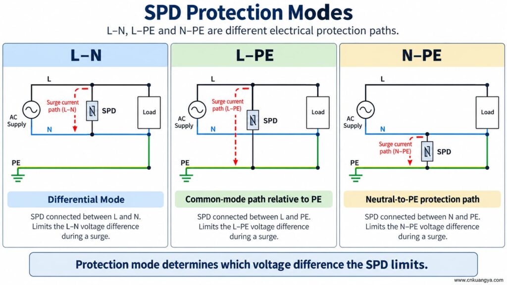
SPD가 접지나 PE 없이 작동할 수 있습니까? SPD가 활선 도체 간의 보호 모드만 가지고 있다면, 해당 모드는 도체 간의 전압 차이에 반응할 수 있습니다. 그러나 PE 의존적 보호 모드는 PE 연결이 누락되면 설계된 대로 작동할 수 없습니다.
이는 다음 두 가지 진술이 모두 참일 수 있음을 의미합니다:
따라서 SPD의 상태 표시등이 녹색으로 표시된다는 이유만으로 PE 연결을 제거하거나 우회하거나 임의로 변경하지 마십시오.
상태 표시창은 일반적으로 모니터링되는 내부 메커니즘의 상태를 나타낼 뿐입니다. 외부 PE 도체가 존재하는지, 본딩 시스템이 올바른지, 또는 연결 길이가 허용 가능한 범위 내에 있는지를 보장하지는 않습니다.
SPD가 L-PE, N-PE, DC+-PE 또는 DC--PE 보호 경로로 설계되었는데 PE 연결이 끊어지면, 해당 모드는 더 이상 의도된 외부 연결을 갖지 못하게 됩니다.
가능한 결과는 다음과 같습니다:
보호 도체 누락은 SPD 문제 해결을 위한 지름길이 아닙니다. 설비는 장비 지침 및 관련 전기 규정에 따라 자격을 갖춘 사람이 점검하고 수정해야 합니다.
“SPD가 접지 없이 작동할 수 있는가?”에 대한 답변은 TN, TT 및 IT 계통의 접지 구조가 다르기 때문에 달라집니다.
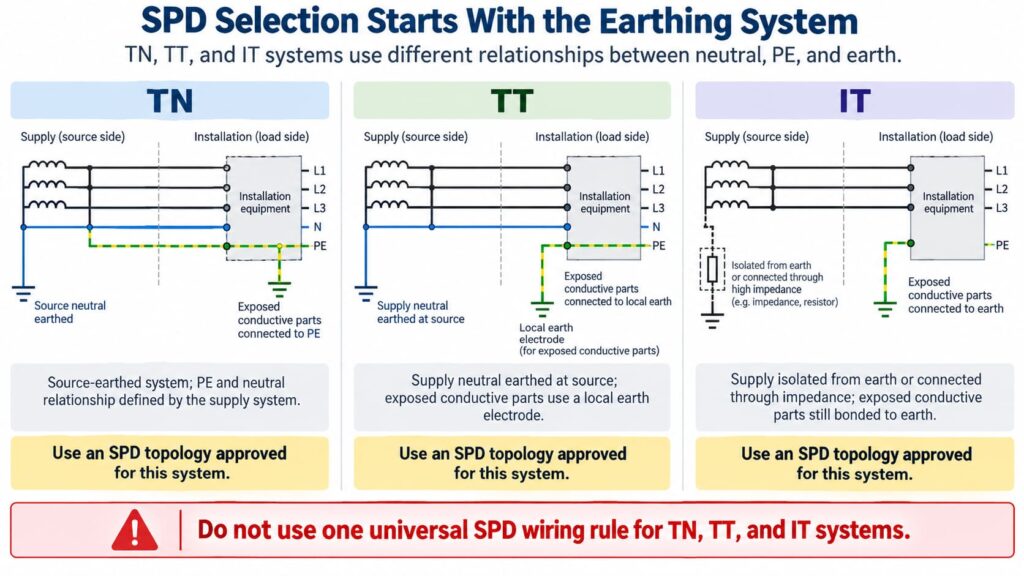
TN-S 구성에서 중성선과 보호 도체(PE)는 설비 내에서 분리된 도체입니다. SPD는 해당 계통 구성 및 보호 모드에 맞게 선정되고 연결되어야 합니다.
TN-C-S 시스템에서 상위 PEN 도체는 정의된 지점에서 별도의 N과 PE로 분리됩니다. TN-S 구간에 설치되는 SPD는 해당 시스템 구간에 적합해야 합니다. 정확한 연결 방식은 제품 지침 및 현지 요구 사항을 따라야 합니다.
SPD 옆에 임의로 “더 나은 접지”를 만들기 위해 중성선-접지 간 추가 연결을 생성하지 마십시오. 중성선/PE 본딩은 시스템 설계 문제이며, SPD 성능 향상을 위한 현장 수정 사항이 아닙니다.
In a TT system, the installation’s exposed conductive parts are connected to a local earth electrode while the supply neutral has its own source earthing arrangement.
This affects SPD topology, protection modes, temporary overvoltage behavior, and coordination with protective devices. Depending on the design, manufacturers often provide specific TT-compatible SPD arrangements rather than treating a TN model as universally interchangeable.
The correct question is therefore not “Does TT have a ground rod?” but:
Is this SPD and its connection arrangement specifically suitable for the TT system at this installation point?
In an IT system, the supply may be isolated from earth or connected to earth through an impedance, while exposed conductive parts remain earthed according to the installation design.
This creates different voltage conditions, especially during a first insulation fault. An SPD used in an IT system must therefore be explicitly suitable for that system and for the possible continuous and temporary voltages it can experience.
Do not choose an SPD for an IT system solely because its Uc value appears high enough.
For AC SPDs, IEC 61643-11:2025 specifies performance and safety requirements for SPDs connected to AC low-voltage power systems. System selection and installation still require coordination with the actual network and installation rules. See the IEC 61643-11:2025 publication page.
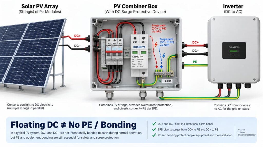
In solar PV systems, the question “can an SPD work without ground?” becomes even more complicated because the DC circuit may be intentionally floating.
Many PV DC circuits operate with neither DC+ nor DC− intentionally bonded directly to earth during normal operation. This is often described as a floating or unearthed DC array.
But that does not mean the whole PV installation has no protective earth, bonding or surge path to PE.
A PV SPD may provide coordinated protection between:
Some PV SPDs use a Y-type internal circuit specifically intended for photovoltaic applications. The correct arrangement depends on the inverter topology, PV earthing arrangement, maximum PV voltage, insulation-monitoring concept and the manufacturer’s approved circuit.
This is why a floating PV system can still use a PE-connected SPD arrangement.
IEC 61643-31 applies to SPDs intended for the DC side of photovoltaic installations up to 1500 V DC and covers their performance characteristics, safety requirements, test methods and ratings. See the IEC 61643-31 publication page.
Before selecting a PV SPD, also verify Ucpv, In, Imax, Up and Iscpv. Our DC SPD 사양 가이드를 참조하십시오. explains what these markings mean and why the largest kA number is not enough.
아니요.
A 2P or 3P description does not automatically tell you:
For the same reason, AC module count can also be misleading. If you are comparing neutral/PE arrangements, see our 3+1 대 4+0 SPD 비교.
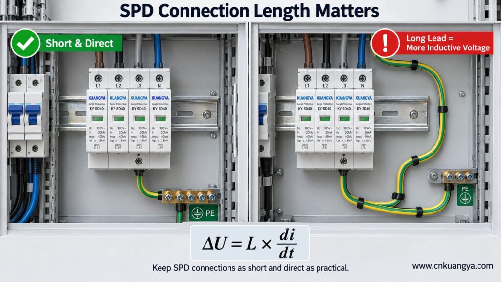
An SPD can be correctly selected and correctly connected to PE, yet still provide poorer installed protection because the connection conductors are too long.
The reason is conductor inductance.
During a fast-rising surge current, additional voltage develops across the SPD connecting conductors:
ΔU = L × di/dt
여기서:
This means the equipment does not necessarily see only the SPD’s datasheet voltage protection level Up. The installed voltage can also include voltage developed across the connection path.
Schneider Electric’s Electrical Installation Guide recommends keeping the total SPD connection length to the network and earth terminal block at no more than approximately 50 cm in the illustrated arrangement and explains the added inductive voltage created by longer conductors. See its SPD connection guidance.
The current consolidated IEC installation standard is IEC 60364-5-53:2019 + Amendment 1:2020 + Amendment 2:2024, which includes Clause 534 for surge protective devices. See the IEC 60364-5-53 consolidated publication page.
If you want a deeper explanation of why conductor length matters during a surge, read our guide on SPD distance from the inverter and connection lead length.
So when asking whether an SPD can work without ground, the quality and length of the PE connection are just as important as whether a protective-earth conductor is physically present.
Trying to reduce lead length by bypassing the approved panel bonding arrangement and connecting an SPD to a separate, isolated earth electrode can create a different problem: the installation may no longer be equipotentially bonded as required.
The correct objective is not “find the nearest piece of earth.”
올바른 질문은 다음과 같습니다.
Connect the SPD to the manufacturer-specified PE/bonding point using the shortest practical, low-impedance path permitted by the system design.
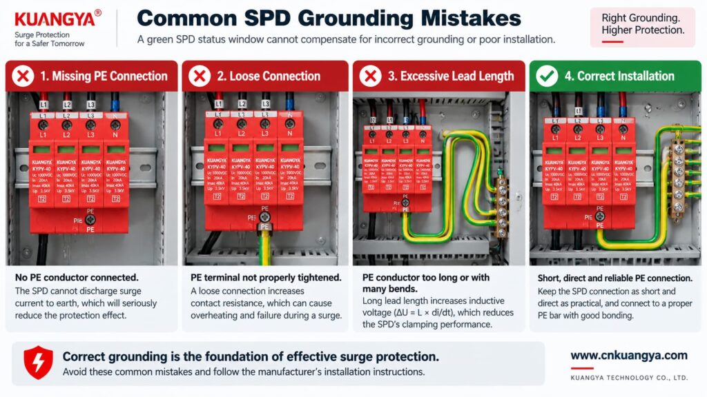
Poor grounding is not one single failure mode. The effect depends on what is actually wrong.
| 문제 | Possible Effect | 확인해야 할 사항 |
|---|---|---|
| PE conductor missing | PE-dependent protection modes may not function as intended | Wiring diagram, PE continuity, bonding arrangement |
| Loose PE terminal | Unstable/high-impedance surge path, heating or arcing risk under fault conditions | Terminal condition and specified torque |
| Very long SPD connection | Higher installed residual voltage due to inductive voltage | Lead length and routing |
| Large conductor loop | Higher inductive coupling and loop impedance | Routing and loop area |
| Wrong TN/TT/IT SPD topology | Incorrect protection modes or unsuitable voltage stress | System earthing arrangement and manufacturer approval |
| Unbonded conductive systems | Dangerous transient potential differences may remain | Equipotential bonding of incoming services and installation |
| Green SPD indicator but external wiring fault | False confidence | Inspect the complete installation, not only the indicator |
Not by itself.
This is another important distinction.
A low measured earth-electrode resistance can be useful for the earthing system, but SPD performance during a fast transient also depends heavily on:
Therefore, a long conductor to an excellent earth electrode can still develop significant transient voltage during a steep surge current.
For surge protection, think in terms of impedance and equipotential bonding, not only DC or low-frequency resistance.
Can an SPD work without ground when it only protects L–N? It may limit the voltage between L and N if that is an approved protection mode of the device.
However, three cautions are essential.
If a surge raises both L and N relative to PE, an L–N element may see relatively little differential voltage even though the equipment is experiencing a large common-mode voltage relative to earth.
Electronic equipment can have chassis connections, signal cables, communication ports, antennas, shields or other conductive interfaces that create additional surge paths.
Do not intentionally leave a PE terminal disconnected on an SPD that is designed to use it. The correct wiring diagram is part of the product’s protection concept.
A backup fuse or circuit breaker does not replace grounding.
Likewise, grounding does not replace backup overcurrent protection where the SPD manufacturer requires it.
| Component / Function | Main Role |
|---|---|
| SPD | Limits transient overvoltage and diverts surge current through defined protection modes |
| PE / bonding system | Provides protective bonding and reference/discharge paths according to the installation design |
| Backup fuse or circuit breaker | Helps isolate fault current according to the SPD manufacturer’s coordination requirements |
| Earth electrode | Connects the installation earthing system to earth |
| Voltage protection relay / regulator | Addresses longer-duration abnormal voltage depending on device type |
If you are selecting upstream protection, see our practical guide: does an SPD need a backup fuse or circuit breaker?
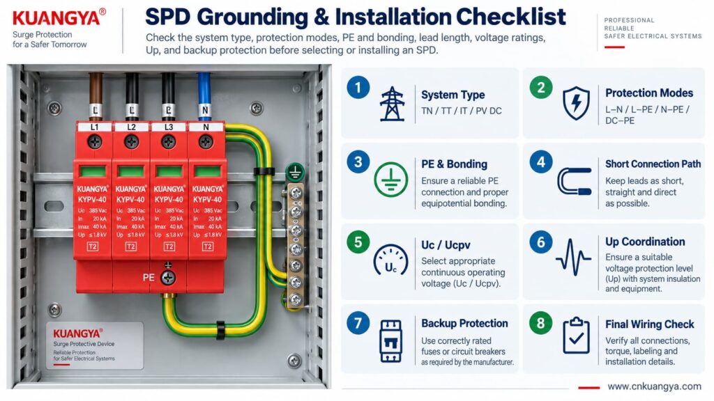
Use the following sequence as a design and inspection checklist. It is not a substitute for local electrical rules or the manufacturer’s instructions.
Confirm whether the circuit is:
Read the internal circuit or wiring diagram, not only the product front label.
Look for protection paths such as L–N, L–PE, N–PE, L1/L2/L3 relationships, DC+–PE and DC−–PE.
Connect only to the approved PE or bonding terminal shown by the manufacturer and installation design.
Avoid unnecessary conductor loops, coils and wide separation between surge-current paths.
For AC, confirm Uc and the applicable system voltage. For PV, confirm Ucpv against the maximum possible PV voltage, including cold-weather Voc where relevant.
Remember that installed protection depends on both the SPD’s Up and the voltage contribution of the connecting conductors.
Verify the manufacturer’s maximum backup fuse / circuit-breaker requirements and the prospective short-circuit conditions.
If an inverter already contains an SPD, do not assume external surge protection is unnecessary. Cable distance, system architecture and the location of the built-in SPD still matter. See our guide on solar inverter built-in SPD and external SPD requirements.
Before deciding whether an SPD can work without ground in a real installation, check the complete protection system rather than judging the SPD alone.
| 확인 | 질문 | 중요한 이유 |
|---|---|---|
| 시스템 | TN, TT, IT, AC or PV DC? | Determines compatible SPD topology |
| 보호 모드 | Which conductor pairs are protected? | Shows what voltage differences the SPD can limit |
| PE 연결 | Is PE required and correctly connected? | Essential for PE-dependent protection modes |
| Bonding | Are relevant conductive systems equipotentially bonded? | Reduces dangerous transient potential differences |
| Lead length | Are SPD connections as short and direct as practical? | Reduces added inductive voltage |
| 전압 | Is Uc / Ucpv correct? | Avoids continuous overvoltage stress |
| Protection level | Is Up coordinated with the equipment? | Determines residual voltage stress |
| Surge rating | Are In, Imax and/or Iimp suitable? | Matches expected surge duty |
| Short-circuit conditions | Are SCCR / Iscpv and backup protection suitable? | Important for safe failure and isolation |
| Manufacturer diagram | Does the installed wiring match the approved circuit? | Prevents topology mistakes |
For photovoltaic projects, KUANGYA provides DC 서지 보호 장치 for different PV voltage classes and installation requirements. Final model selection should always be based on the actual PV voltage, earthing arrangement, protection mode, SPD type and system fault conditions.
Sometimes an individual protection mode such as L–N can operate without a direct PE connection. However, that does not mean the complete surge-protection system can ignore PE, earthing or equipotential bonding. Any SPD mode designed to operate between a live conductor and PE requires the intended PE connection.
When people ask “can an SPD work without ground?”, the answer depends on the SPD circuit rather than on one universal rule. Some devices or protection modes operate only between active conductors, while many power SPDs include PE-related protection modes. Follow the manufacturer’s circuit diagram and select the SPD for the actual TN, TT, IT or DC/PV system.
The SPD may still operate, but a long connection can add inductive voltage during a fast-rising surge current. This can increase the voltage that appears at the protected equipment. Short, direct connections are therefore an important part of SPD installation.
Do not improvise an isolated grounding path simply to make the SPD conductor shorter. The SPD should be connected to the approved PE/bonding point in accordance with the system design, manufacturer instructions and applicable electrical rules.
Not by itself. Surge performance also depends on high-frequency impedance, connection length, conductor routing, loop area, bonding and the SPD’s protection characteristics. A low earth-electrode resistance does not compensate for poor SPD wiring.
Yes. A PV DC system may have neither polarity intentionally grounded during normal operation while still using a properly designed SPD arrangement with protection paths to PE. Use a PV SPD approved for that topology and voltage.
No. A status indicator normally reports the condition of the SPD’s internal monitoring or disconnection mechanism. It does not verify external PE continuity, bonding, conductor length or correct earthing-system selection.
No. An SPD and the installation’s protective-earthing/bonding system perform different functions. A surge protective device should be considered part of a coordinated electrical protection system, not a replacement for protective earthing.
Grounding and bonding are fundamental parts of electrical safety and lightning/surge protection, but they do not perform the same voltage-limiting function as an SPD at equipment terminals. A complete design may require both, depending on the installation.
There is no single standard that answers every installation question. IEC 61643-11 covers AC low-voltage SPD product requirements, IEC 61643-31 covers PV DC SPD product requirements, and IEC 60364-5-53 includes installation requirements for low-voltage electrical installations, including Clause 534 for SPDs. Project-specific lightning-protection and national wiring requirements may also apply.
SPD가 접지 없이 작동할 수 있습니까? The answer cannot be reduced to a simple yes or no.
An SPD limits voltage across specific protection modes. A mode between active conductors, such as L–N, may operate without directly using PE. But any protection mode that depends on L–PE, N–PE, DC+–PE or DC−–PE requires the designed PE/bonding path.
More importantly, surge protection is a system function.
A correctly selected SPD can still perform poorly if:
For that reason, do not ask only:
“Does this SPD have a ground terminal?”
Ask instead:
“What voltage differences must be limited, what protection modes does this SPD provide, and how is the complete system bonded and earthed?”
That question leads to a much safer and more technically correct SPD selection.
Technical note: This article is intended for product selection and engineering education. Actual SPD installation must follow the device manufacturer’s wiring instructions, the applicable electrical installation standard, and local code requirements.

