웽양 공업구 웨칭 원저우 325000
근무 시간
월요일~금요일: 오전 7시~오후 7시
주말: 주말: 오전 10시 - 오후 5시
웽양 공업구 웨칭 원저우 325000
근무 시간
월요일~금요일: 오전 7시~오후 7시
주말: 주말: 오전 10시 - 오후 5시

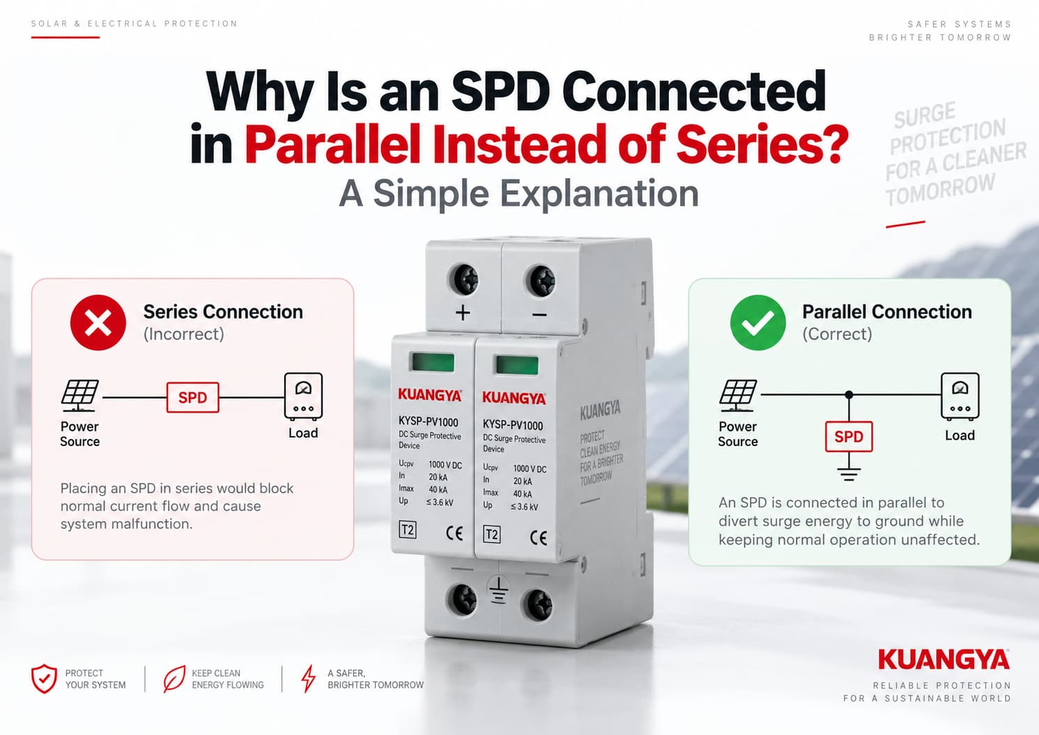
일반적인 서지 보호 장치(SPD) 설치 사례를 보면 퓨즈나 차단기와는 다른 점을 발견할 수 있습니다.
퓨즈나 차단기는 일반적으로 회로와 직렬로 설치되므로 부하 전류가 이를 통과합니다.
일반적인 전원용 서지 보호 장치(SPD)는 대개 병렬로 연결됩니다 보호 대상 회로와 병렬로 연결되기 때문에 많은 설치 기사들이 왜 SPD를 직렬이 아닌 병렬로 연결하는지 질문합니다..
왜 그럴까요?
간단히 말해 병렬 연결된 SPD는 정상 부하 전류를 통과시킬 필요가 없습니다. 정상 작동 조건에서는 고임피던스 상태를 유지합니다. 과도 과전압이 발생하면 SPD가 도통 상태가 되어 서지 전류를 위한 저임피던스 경로를 제공함으로써 보호 대상 장비에 도달하는 전압을 제한합니다.
이것이 전력 배전 및 태양광 발전 시스템에서 Type 1 및 Type 2 SPD에 병렬 연결이 널리 사용되는 이유입니다.
하지만 “SPD = 항상 병렬”이 절대적인 규칙은 아닙니다. 특정 용도를 위한 직렬 연결형 SPD 및 서지 필터도 존재합니다. 이 글에서는 주로 AC 배전 및 태양광 DC 시스템에 사용되는 일반적인 병렬 연결형 전원 SPD에 대해 다룹니다.
일반적인 병렬로 연결된 SPD 부하의 정상 작동 전류를 통과시키지 않고 일시적인 과전압 이벤트에 대응하도록 설계되었습니다.
정상적인 조건에서:
전원 → 부하
SPD는 대기 상태를 유지합니다.
서지가 발생하면 SPD는 전기적 특성을 변경하여 보호 경로를 통해 서지 전류를 흐르게 함으로써 민감한 장비에 가해지는 전압을 제한합니다.
단순화된 병렬 구성은 다음과 같습니다:
전원 ───────────── 부하
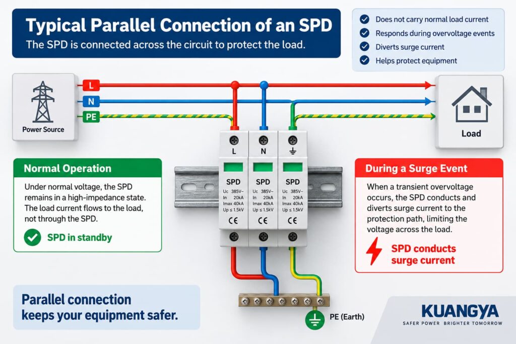
SPD는 정상 부하 전류 경로에 직접 삽입되는 것이 아니라 회로 양단에 연결됩니다. 피닉스 컨택트(Phoenix Contact)의 서지 보호 기초 또한 SPD는 보호 대상 장비와 병렬로 설치하거나 관련 도체 사이에 설치할 수 있다고 설명합니다.
이튼(Eaton)은 병렬 또는 션트(shunt) 연결형 SPD를 동일한 방식으로 설명합니다. 즉, 연결 도체는 정상 공급 전류를 전달하지 않고 과도 현상과 관련된 짧은 지속 시간의 전류를 전달합니다.
이러한 기본적인 차이점이 대부분의 일반적인 전원 SPD가 병렬로 설치되는 이유를 설명합니다.
병렬 연결을 이해하려면 먼저 서지가 없을 때 SPD가 어떤 역할을 하는지 이해하는 것이 도움이 됩니다.
정상 작동 중에는 시스템 전압이 SPD가 유의미하게 도통되는 수준 미만으로 유지됩니다.
MOV 기반 SPD의 경우, 보호 소자는 정상 전압 조건에서 비교적 높은 임피던스를 나타냅니다.
이는 주 작동 전류가 정상 전원 회로를 통해 부하로 계속 흐른다는 것을 의미합니다.
SPD는 본질적으로 대기 상태에 있습니다.
간략하게 표현하면 다음과 같습니다:
전원 ───────────────── 부하
이것이 모든 SPD에 전류가 전혀 흐르지 않는다는 것을 의미하는 것은 아닙니다. SPD의 기술 및 설계에 따라 미세한 누설 전류나 동작 전류가 존재할 수 있습니다.
중요한 점은 다음과 같습니다:
일반적인 병렬 연결형 SPD의 경우, 정상 부하 전류가 SPD를 통과할 필요가 없습니다.
SPD를 장비의 동작 전류를 지속적으로 전달해야 하는 부품이 아니라, 주 회로 옆에서 대기하는 보호 경로로 생각하십시오.
서지는 낙뢰 관련 과도 현상이나 스위칭 동작과 같은 이벤트로 인해 발생할 수 있는 단시간의 전압 상승을 의미합니다.
SPD 양단 전압이 충분히 상승하면 SPD의 보호 소자가 도통되기 시작합니다.
보호 소자가 과도 전압에 어떻게 반응하는지에 대한 자세한 설명은 당사의 가이드를 참조하십시오. DC SPD의 작동 원리.
정상 상태와 비교하여 임피던스가 급격히 감소합니다.
이를 통해 서지 전류가 가용한 보호 경로로 흐르게 되며, 보호 대상 장비에 나타나는 과도 전압을 제한합니다.
단순화된 표현은 다음과 같습니다.
장비
그러나 이 다이어그램은 단순화된 예시일 뿐입니다.
SPD는 모든 서지를 항상 직접 접지로 분산시키지는 않음.
전기 시스템 및 SPD 설계에 따라 다음과 같은 보호 모드가 존재할 수 있음:
이러한 이유로 다음과 같이 표현하는 것이 더 정확합니다:
서지 보호 장치(SPD)는 서지 전류를 위한 제어된 경로를 제공하며, 보호 대상 장비에 걸리는 과도 전압을 제한합니다.
정확한 전류 경로는 SPD 구성 및 시스템 토폴로지에 따라 달라집니다.
SPD가 병렬로 연결되는 이유를 이해하려면 정상 작동 시와 서지 발생 시 어떤 일이 일어나는지 살펴보는 것이 도움이 됩니다.
다음과 같은 몇 가지 중요한 이유로 병렬로 연결된 SPD 전력 분배 시스템에서 널리 사용됩니다.
이것은 SPD와 회로 차단기 또는 퓨즈와 같은 장치 간의 가장 큰 차이점 중 하나입니다.
인버터가 일반적으로 수십 암페어에서 작동한다고 가정해 보십시오.
일반적인 병렬 연결형 SPD의 경우, 동작 전류가 SPD를 지속적으로 통과할 필요가 없습니다.
대신:
전원 ───────────────── 부하
SPD는 보호 대상 회로에 병렬로 연결됩니다.
이는 SPD를 모든 하위 부하의 전체 동작 전류가 아닌, 서지 보호 요구 사항에 따라 우선적으로 선택할 수 있음을 의미합니다.
피닉스 컨택트(Phoenix Contact) 역시 병렬로 설치된 자사의 전원 SPD가 회로의 정격 전류를 직접 통과시키는 것이 아니라, 배전 시스템에 분기 형태로 연결된 전기적 특성을 가진다고 언급합니다.
일반적인 SPD는 전압 감응형입니다.
정상적인 시스템 전압 상태에서는 대부분 비활성 상태를 유지합니다.
과도 전압이 정상 작동 범위를 초과하여 상승하면 보호 소자가 도통되기 시작합니다.
이는 퓨즈, 회로 차단기 또는 절연 스위치와는 근본적으로 다릅니다.
예를 들어
퓨즈
전원 → 퓨즈 → 부하
회로 차단기
전원 → 차단기 → 부하
일반적인 병렬형 SPD
전원 ────────── 부하
퓨즈나 차단기는 물리적으로 부하 경로상에 위치하므로 일반적으로 회로 전류를 통과시켜야 합니다.
병렬형 SPD는 그렇지 않습니다.
SPD의 목적은 부하에 도달하기 전 모든 서지를 “차단”하는 것이 아닙니다.
대신, 전압 제한형 SPD는 상승하는 과도 전압에 반응하여 서지 전류를 도통시킵니다.
이러한 동작은 보호 대상 회로 양단의 전압을 제한합니다.
예를 들어, 간소화된 태양광(PV) 시스템에서:
PV 어레이 ───────────────── 인버터
정상 작동 중에는 PV 전력이 인버터 쪽으로 계속 흐릅니다.
서지 발생 시, SPD는 보호 모드에 따라 작동하여 과도 전압이 도달할 수 있는 수준보다 낮게 유지되도록 돕습니다.
이것이 SPD를 회로에 병렬로 설치하는 기본적인 이유입니다.
일반적인 SPD는 병렬 분기로 연결되기 때문에 전원과 부하 사이의 정상적인 전도 경로가 되지 않습니다.
이는 실무적으로 중요한 이점을 제공합니다.
시스템의 정상 작동 전류는 SPD 보호 요소를 지속적으로 통과할 필요가 없습니다.
물론, 이것이 설치 후 SPD를 무시해도 된다는 의미는 아닙니다.
SPD는 비정상적인 전기적 스트레스 후 성능이 저하되거나 연결이 끊어질 수 있으므로, 상태 표시를 주기적으로 확인해야 합니다.
SPD가 병렬로 연결되는 이유를 이해하면, 일반적인 분기형(shunt-connected) SPD가 왜 정상 부하 경로와 직렬로 배치되지 않는지도 설명할 수 있습니다.
회로 차단기와 퓨즈는 회로 전류를 통과시켜야 하므로 일반적으로 직렬로 설치됩니다. 일반적인 병렬형 SPD는 이와 다른 기능을 수행하도록 설계되었습니다.
진정한 직렬 연결은 다음과 같은 형태입니다:
전원 → 장치 → 부하
만약 전체 SPD 어셈블리가 부하 경로에 삽입된다면, SPD는 연속적인 부하 전류를 수용해야 할 것입니다.
해당 장치의 도체, 단자, 열 설계, 단락 성능 및 고장 동작은 모두 해당 애플리케이션에 맞게 설계되어야 합니다.
이것이 일반적인 DIN 레일 타입 1 또는 타입 2 병렬 SPD가 통상적으로 사용되는 방식은 아닙니다.
이는 SPD 명판을 읽을 때 특히 중요한 사항입니다.
SPD가 다음과 같이 표시되어 있다고 가정해 보십시오:
In = 20 kA
및
Imax = 40 kA
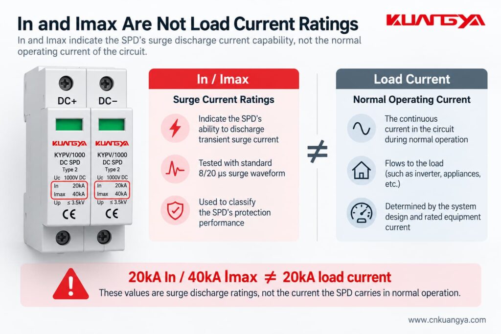
이러한 SPD 정격이 여전히 혼란스럽다면, 당사의 DC SPD 사양 가이드를 참조하십시오. Ucpv, In, Imax, Up 및 Iscpv에 대해 더 자세히 설명합니다.
이 수치들은 not SPD가 20 kA 또는 40 kA의 정상 부하 전류를 지속적으로 통전하도록 설계되었음을 의미하지 않습니다.
Type 2 SPD의 경우, In 는 8/20 μs 전류 임펄스와 관련된 공칭 방전 전류를 의미하며, Imax 는 8/20 μs 임펄스와 관련된 최대 방전 전류를 의미합니다.
피닉스 컨택트(Phoenix Contact)의 기술적 정의 또한 In과 Imax를 정상적인 연속 부하 전류 정격이 아닌, SPD를 통해 흐르는 임펄스 전류 값으로 설명합니다.
따라서:
In과 Imax는 서지 방전 전류 정격입니다. 이는 부하의 정상 작동 전류가 아닙니다.
이 구분은 SPD를 선정하거나 설명할 때 매우 중요합니다.
아니요.
이것은 중요한 예외 사항입니다.
본 기사에서 다룬 일반적인 Type 1 및 Type 2 전원용 SPD는 일반적으로 병렬로 설치되지만, 직렬 연결형 SPD 어셈블리와 직렬 연결형 서지 필터도 존재합니다.
슈나이더 일렉트릭은 직렬 연결형 제품은 특정 부하 근처에 인라인으로 설치되는 경우가 많으며, 병렬 연결형 SPD는 배전반 및 분전반에서 더 일반적으로 사용되는 방식이라고 언급합니다.
직렬 연결형 제품은 회로의 부하 전류를 통과시킬 수 있도록 특별히 설계되어야 합니다.
따라서 다음과 같이 말하는 것은 옳지 않습니다.
“SPD는 절대 직렬로 연결할 수 없다.”
더 기술적으로 정확한 설명은 다음과 같습니다:
가장 일반적인 배전용 Type 1 및 Type 2 서지 보호 장치(SPD)는 병렬로 연결되지만, 특정 용도를 위해 특별히 설계된 직렬 연결형 서지 보호 제품도 존재합니다.
태양광 PV 및 일반 배전반 애플리케이션의 경우, 항상 해당 SPD 제조사의 배선도를 따르십시오.
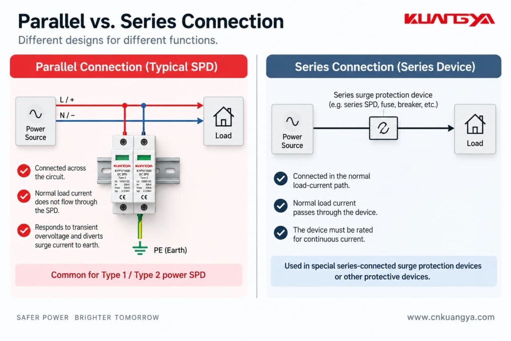
아래 표는 일반적인 병렬로 연결된 SPD 장치가 정상 부하 전류 경로에 직접 설치된 장치와 어떻게 다른지 보여줍니다.
| 기능 | 일반적인 병렬형 SPD | 직렬 연결 장치 |
|---|---|---|
| 일반 부하 경로에 직접 연결 | 아니요 | 예 |
| 일반 부하 전류가 장치 전체를 통과 | 아니요 | 예 |
| Type 1 / Type 2 전원 SPD의 일반적인 구성 | 예 | 흔하지 않은 방식 |
| 주요 용도 | 서지 전류 경로를 제공하여 과도 과전압을 제한 | 제품 설계에 따라 다름 |
| 장치 전체에 대해 연속 전류 정격이 중요함 | 일반적으로 인라인 장치와 동일한 방식은 아님 | 예 |
| 설치 리드선의 길이는 보호 성능에 영향을 미침 | 예 | 내부 배치는 외부 병렬 리드선의 길이 영향을 줄일 수 있습니다. |
| 주요 적용 분야 | 분전반, 장비 인입구, 태양광(PV) 시스템 | 선별된 민감 부하 또는 특수 보호/필터링 애플리케이션 |
중요한 점은 한 가지 방법이 보편적으로 “좋고” 다른 방법이 “나쁘다”는 것이 아닙니다.”
이들은 서로 다른 제품 아키텍처입니다.
그러나 일반적인 DIN 레일 전원 SPD의 경우, 병렬 연결이 일반적으로 권장되는 설치 방식입니다.
동일한 원리가 많은 태양광 시스템에도 적용되며, 여기서 SPD는 제조업체의 배선 구성에 따라 DC 회로와 병렬로 연결됩니다.
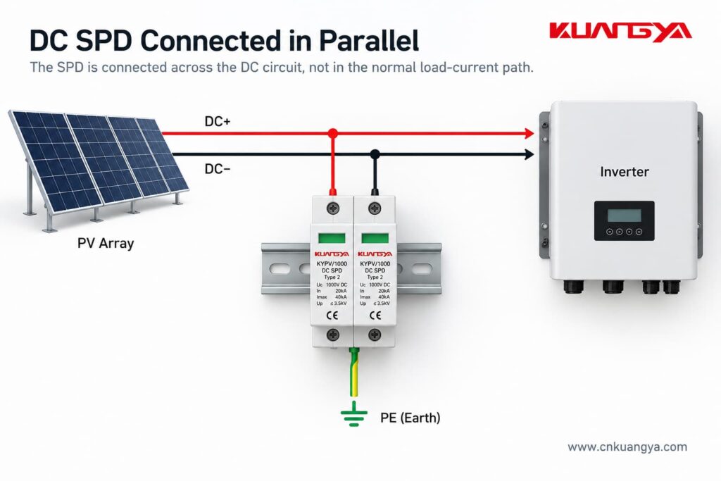
그러나 DC SPD 배선은 각별한 주의가 필요합니다.
모든 PV SPD가 단순히 다음과 같이 배선된다고 가정하는 것은 옳지 않습니다:
DC+ → SPD → PE
실제 내부 보호 회로는 다를 수 있습니다.
제품 및 PV 시스템 구성에 따라 SPD는 다음과 같은 모드 간의 보호 기능을 제공할 수 있습니다:
접지 시스템 및 태양광(PV) 아키텍처에 따라 서로 다른 SPD 회로 구성이 사용됩니다.
병렬로 연결된 PV SPD의 경우, 정확한 단자 배열은 여전히 SPD 설계, 시스템 토폴로지 및 제조업체의 배선도에 따라 달라집니다.
이것이 바로 SPD에 인쇄되어 있거나 제조업체의 설치 지침서에 제공된 배선도가 매우 중요한 이유입니다.
태양광 DC 애플리케이션의 경우, 전용 IEC 제품 표준은 IEC 61643-31입니다. DEHN은 또한 PV 및 저전압 SPD 애플리케이션과 관련된 설치 표준으로 IEC 60364-7-712 및 IEC 60364-5-53을 명시하고 있습니다.
AC 및 DC SPD는 유사한 서지 보호 원리를 기반으로 하지만, 두 시스템은 상호 교환할 수 없습니다.
직류(DC) 시스템은 자연적인 영점 교차(zero crossing)가 없어 직류 아크 차단이 더 어렵기 때문에 추가적인 문제를 야기합니다.
이러한 이유로 서지 보호 장치(SPD)는 직류 전압, 시스템 구성 및 애플리케이션에 특별히 적합해야 합니다.
항상 다음 사항을 확인하십시오:
설치 전.
KUANGYA KYPV/1000 Type 2 DC SPD를 예로 들면, 명판에는 다음과 같은 매개변수가 포함될 수 있습니다:
이 값들은 SPD의 전기적 성능 중 서로 다른 부분을 설명합니다.
Uc는 SPD에 대해 지정된 최대 연속 작동 전압입니다.
적절한 전압 정격을 선택할 때는 시스템 전압과 가능한 작동 조건을 고려해야 합니다.
In은 공칭 방전 전류입니다.
Type 2 SPD의 경우, 이는 8/20 μs 임펄스 전류 파형과 관련이 있습니다.
Imax는 SPD에 대해 지정된 최대 방전 전류이며, 이 유형의 장치에 대해서도 8/20 μs 파형과 관련이 있습니다.
Imax는 In과 같거나 그보다 큽니다.
Up은 전압 보호 레벨입니다.
이는 지정된 시험 조건 하에서 SPD의 전압 제한 성능을 나타냅니다.
오늘 주제의 핵심은 다음과 같습니다.
20 kA In 및 40 kA Imax는 정상 작동 중에 20 kA 또는 40 kA가 SPD를 통해 지속적으로 흐른다는 것을 의미하지 않습니다.
이는 과도 서지 전류 매개변수입니다.
이것이 바로 SPD의 In 또는 Imax를 인버터의 부하 전류와 직접 비교하는 것이 옳지 않은 또 다른 이유입니다.
아니요.
In fact, connection length is extremely important for a parallel-connected SPD.
A surge has a very fast current rise.
The connecting conductors therefore have inductance, and the rapidly changing surge current can create an additional voltage drop along those conductors.
That additional voltage is effectively added to the voltage experienced by the protected equipment.
에 따르면 NEMA’s guidance on hard-wired SPD installation, the size and length of the connecting leads can affect the performance of a parallel-connected SPD, and short, direct connections are preferred.
Phoenix Contact makes the same point: long connecting conductors can increase the effective voltage protection level seen in the installation.
So even if two installations use exactly the same SPD, their real-world protection performance may not be identical if one has much longer connection conductors.
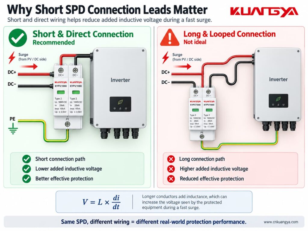
The SPD connection should generally be:
This is also why SPD location matters.
If you want to understand this issue in more detail, see our guide:
The exact position depends on the system being protected.
For example, an SPD may be installed:
If your inverter already includes surge protection, do not assume that an additional external SPD is automatically unnecessary. See 태양광 인버터에 DC SPD가 내장되어 있는 경우, 외부 SPD가 추가로 필요한가요?
The objective is not simply to put “one SPD somewhere in the system.”
The SPD should be positioned as part of a coordinated protection concept.
For PV systems in particular, cable length and the location of the inverter, modules and building entry points can affect whether additional SPDs are appropriate.
에 따르면 DEHN’s photovoltaic surge protection guidance, SPDs should be installed as close as possible to the equipment being protected, such as the inverter, on both the AC and DC sides.
The specific requirements should always be determined from the applicable installation standard, risk assessment and manufacturer instructions.
Sometimes yes, but not always in exactly the same way.
This is another area where oversimplified advice can cause problems.
A parallel SPD may require an external:
depending on the SPD design and installation.
Other SPDs may include internal protective or disconnecting components.
The correct arrangement depends on factors such as:
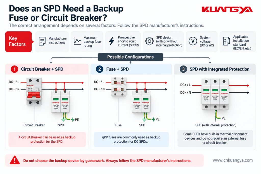
NEMA specifically advises installers to follow the manufacturer’s requirements regarding fuses, breakers and connection leads.
Therefore, do not assume:
“Every SPD needs exactly the same backup breaker.”
And do not assume:
“Because the SPD is connected in parallel, no overcurrent protection is ever required.”
두 진술 모두 틀릴 수 있습니다.
Always check the SPD datasheet and installation instructions.
Imagine two identical SPDs.
The SPD is mounted very close to the protected equipment, with short and direct conductors.
The SPD is several meters away and connected through long conductors.
Although the SPD nameplate is identical, the effective protection at the equipment can be different.
This happens because the connecting conductors contribute additional inductive voltage during a fast surge.
NEMA explains this relationship using:
V = L × di/dt
where:
The faster the current changes and the more inductance there is in the connection, the greater the additional voltage can become.
You do not need to calculate this formula for every normal installation.
실무적인 교훈은 훨씬 더 간단합니다:
Keep SPD connections short and direct.
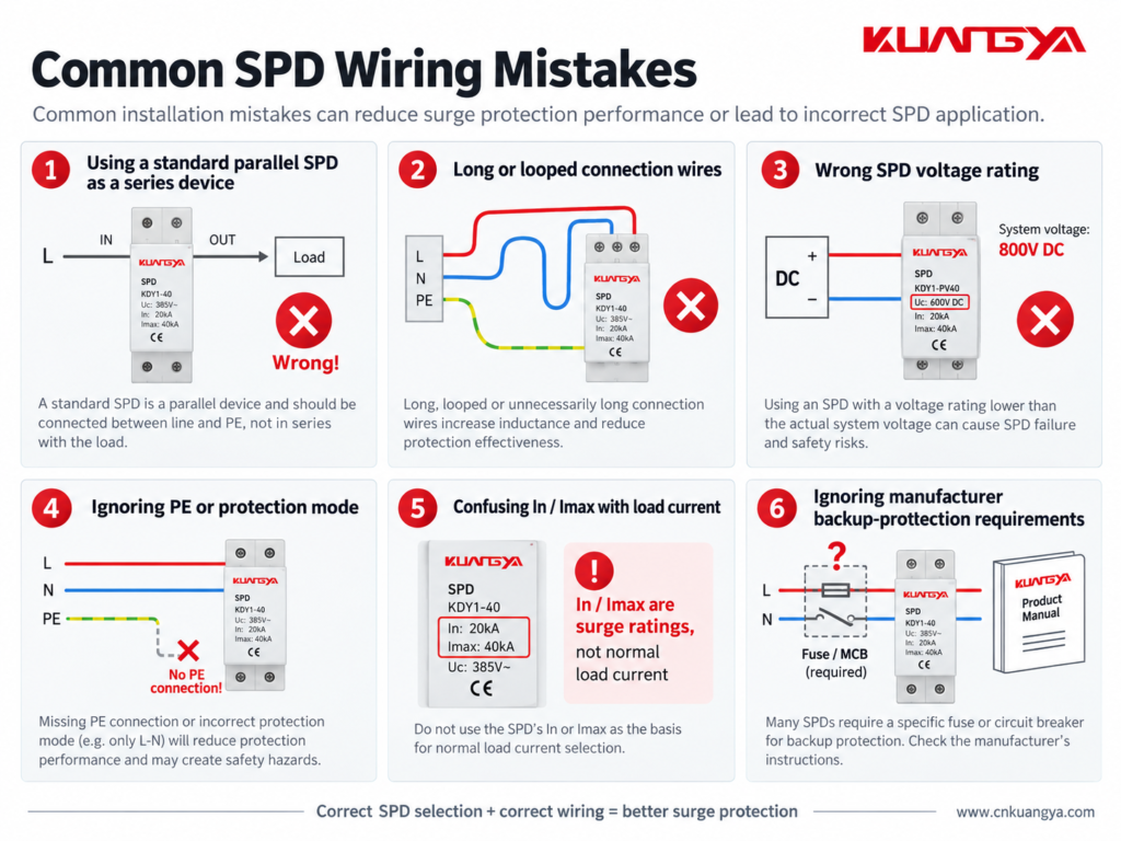
Understanding why the SPD is connected in parallel also makes several common installation mistakes easier to recognize.
Do not simply place a normal parallel DIN-rail SPD in the main load path unless the manufacturer’s design specifically requires that configuration.
Follow the wiring diagram for the exact product.
A good SPD with poor wiring may provide worse protection than expected.
Long leads increase inductive voltage during a surge.
Short and direct routing is generally preferred.
Do not assume every surge simply flows from one line terminal to earth.
The protection modes depend on the electrical network and SPD design.
Correct PE, bonding and circuit connections are essential where required by the product and installation design.
An SPD must be suitable for the voltage that can continuously appear at its terminals.
This is particularly important in PV systems, where string open-circuit voltage changes with temperature.
Choosing an SPD only because it says “DC SPD” is not enough.
The voltage rating must match the actual PV system design.
For a step-by-step method, see our DC SPD voltage selection guide for solar PV systems.
This is one of the most common misunderstandings.
An SPD marked:
In = 20 kA
does not mean:
Normal load current = 20 kA
In and Imax describe surge-current performance under specified impulse conditions.
They are not normal operating-current ratings.
Do not guess the fuse or breaker size.
Different SPD designs can have different backup protection requirements.
Some products also include integrated protective components.
Check the actual product documentation.
Many modular SPDs include a visual status indicator.
If the indicator shows a fault or replacement condition, the protection module may need to be replaced.
Some SPDs also have remote signaling contacts for connection to alarms, PLCs or monitoring systems.
Installing the SPD is only the first step.
Its condition should also be checked during maintenance.
For common warning signs and replacement indicators, see How to Know If an SPD Is Bad?
A circuit breaker and an SPD protect against different electrical problems.
A circuit breaker is mainly intended to interrupt abnormal current conditions such as overloads or short circuits.
Because it must sense and interrupt circuit current, it is connected in series with the load.
An SPD is intended to limit transient overvoltage.
A typical power SPD is connected in parallel so that it can conduct surge current when the transient voltage rises.
That means:
Circuit breaker → current protection
SPD → transient overvoltage protection
One cannot normally replace the other.
They perform different jobs.
The same principle applies to a fuse.
A fuse is installed in series with the circuit it protects.
Normal load current passes through the fuse element.
If excessive current persists, the fuse element opens the circuit.
A typical SPD behaves differently.
It remains connected across the protected circuit and responds mainly when the voltage reaches a level that causes its protective elements to conduct.
So although fuses, breakers and SPDs may all appear in the same electrical panel, their functions and connection methods are not the same.
Most common Type 1 and Type 2 power SPDs used in distribution boards and similar applications are connected in parallel with the circuit they protect.
However, specially designed series-connected SPDs and surge filters also exist.
Always follow the wiring instructions for the exact product.
A typical SPD is connected in parallel because it does not need to carry the normal load current.
During normal voltage conditions, it remains in a high-impedance state.
When a transient overvoltage occurs, it conducts surge current through its protection path and limits the voltage across the protected equipment.
The normal load current does not normally flow through a typical parallel-connected SPD.
However, a small leakage or operating current may exist depending on the SPD technology and design.
Therefore, saying “absolutely no current flows through an SPD” would not be technically precise.
꼭 그렇지는 않습니다.
An SPD may operate between line and neutral, line and earth, neutral and earth, line and line, or different DC conductors depending on its protection modes.
The exact surge-current path depends on the SPD and electrical system configuration.
Many power SPDs are designed to be connected in parallel across the appropriate conductors of the supply.
However, the exact wiring arrangement depends on the SPD type, system earthing arrangement, required overcurrent protection and manufacturer instructions.
Never determine the connection from a generic diagram alone.
A normal parallel SPD is not designed to serve as the continuous main load-current path.
Installing an inline device requires a product specifically designed for that purpose, including suitable current, terminal, fault and thermal ratings.
아니요.
In and Imax are surge-discharge current parameters.
They should not be confused with PV string operating current, short-circuit current or inverter input current.
The general surge-protection principle is similar, but DC and AC systems have important differences.
The voltage rating, polarity, protection modes, earthing arrangement and internal SPD design may differ.
For PV systems, always use an SPD intended for the specific DC application and follow its wiring diagram.
It depends on the protection mode and system design.
Many power SPDs include protection paths involving PE, but not every surge protection mode is simply conductor-to-earth.
Use the manufacturer’s circuit diagram and the applicable earthing and bonding requirements.
예.
Long SPD connection conductors add inductance and can increase the voltage experienced by the protected equipment during a fast transient.
For this reason, connection conductors should generally be kept as short and direct as practical.
If you only remember a few things from this article, remember these:
So, why is an SPD connected in parallel instead of series?
For a typical Type 1 or Type 2 병렬로 연결된 SPD, the normal load current does not pass through the SPD as it would through a series-connected device.
Under normal operating conditions, the SPD remains largely in standby.
When a surge occurs, it conducts through its designed protection path and helps limit the voltage appearing across the protected equipment.
That is fundamentally different from a fuse or circuit breaker, which normally carries the circuit current and is therefore installed in series.
However, correct SPD installation involves more than simply choosing “parallel.”
The SPD voltage rating, protection modes, location, conductor length, earthing and bonding arrangement, backup protection and manufacturer wiring diagram all affect the final protection performance.
For solar PV systems in particular, always use an SPD designed for the relevant DC application and verify the actual system voltage and wiring configuration before installation.

