Zone industrielle WengYang Yueqing Wenzhou 325000
Heures de travail
Du lundi au vendredi : de 7h00 à 19h00
Le week-end : 10H00 - 17H00
Zone industrielle WengYang Yueqing Wenzhou 325000
Heures de travail
Du lundi au vendredi : de 7h00 à 19h00
Le week-end : 10H00 - 17H00

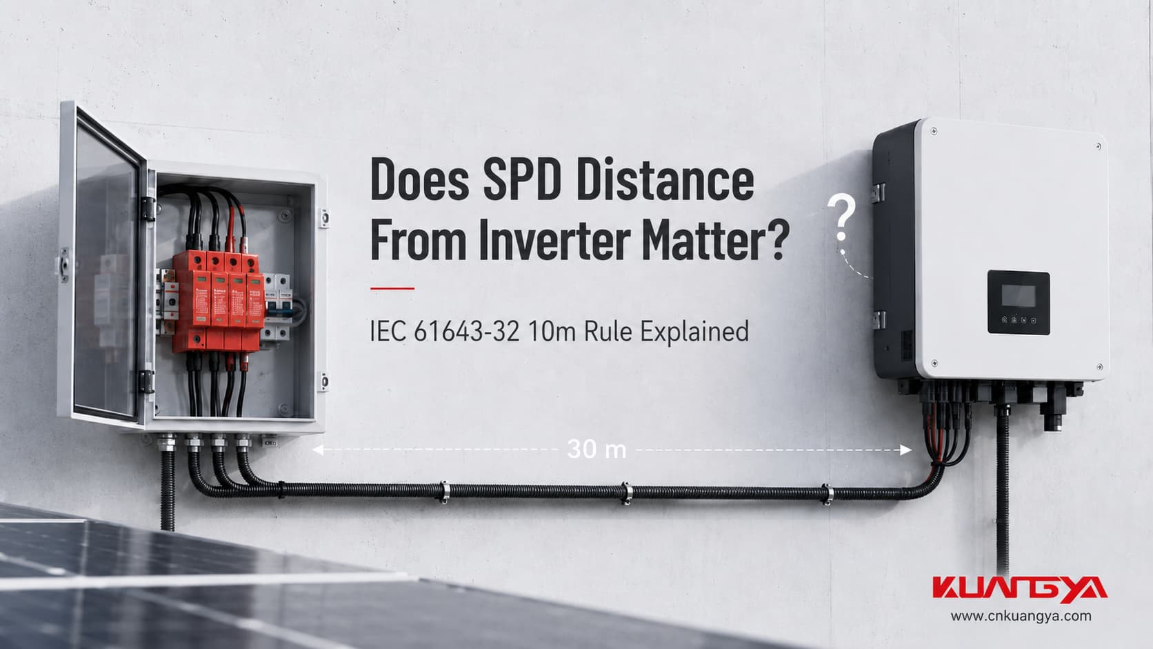
La distance du parafoudre par rapport à l'onduleur est un élément important de la conception de la protection contre les surtensions photovoltaïques, en particulier lorsque le parafoudre est installé dans un coffret de jonction ou à proximité du champ photovoltaïque.
Vous avez installé un dispositif de protection contre les surtensions CC dans le système photovoltaïque, mais le parafoudre se trouve à l'intérieur du coffret de jonction alors que l'onduleur est situé à 20 ou 30 mètres.
Une question très pratique se pose alors :
Ce parafoudre est-il toujours suffisant pour protéger l'onduleur ?
Ou un autre parafoudre devrait-il être installé plus près de l'onduleur ?
La réponse est :
Oui, la distance a une importance.
Dans un système photovoltaïque, la protection contre les surtensions ne dépend pas uniquement de la présence d'un parafoudre (SPD) quelque part sur le circuit CC. La distance entre le champ photovoltaïque et l'onduleur, l'emplacement du parafoudre, la longueur des conducteurs de raccordement du parafoudre, la tension de tenue aux chocs de l'équipement et la disposition de la protection contre la foudre influencent tous le concept de protection final.
IEC 61643-32 traite spécifiquement de la sélection, de l'installation et de la coordination des parafoudres utilisés dans les installations photovoltaïques jusqu'à 1 500 V CC. Elle distingue les courtes et longues distances entre les modules photovoltaïques et l'onduleur et définit des exigences spécifiques pour le placement des parafoudres.
La question correcte n'est donc pas simplement :
“ Ai-je déjà un parafoudre ? ”
C'est :
“ Le parafoudre est-il installé au bon endroit pour protéger l'équipement qui m'intéresse ? ”
Pour les installations photovoltaïques couvertes par les configurations pertinentes de la norme IEC 61643-32 :
Parallèlement, ne confondez pas ceci Distance système de 10 m avec approximativement Recommandation de 0,5 m pour le câble de connexion du parafoudre (SPD).
Ils décrivent deux problèmes électriques différents.
| Question | Réponse pratique |
|---|---|
| La distance entre le champ photovoltaïque et l'onduleur a-t-elle une importance ? | Oui |
| 10 m est-il une règle marketing arbitraire ? | Non. Elle apparaît explicitement dans la norme IEC 61643-32 |
| ≥10 m signifie-t-il toujours la même chose dans tous les pays et pour toutes les installations ? | Non. La norme applicable, les conditions LPS, les règles nationales et la configuration du système restent déterminantes. |
| 0,5 m est-il la distance maximale entre le parafoudre (SPD) et l'onduleur ? | Non |
| À quoi se réfère la valeur de 0,5 m ? | Aux conducteurs de raccordement du parafoudre dans le schéma de câblage applicable. |
| Un parafoudre intégré à l'onduleur peut-il constituer une partie du second étage de protection ? | Potentiellement, si ses spécifications et son installation satisfont à la fonction de protection requise. |
| Un Imax plus élevé peut-il compenser un mauvais positionnement du parafoudre ? | Non |
| Up seul indique-t-il la tension à laquelle l'onduleur sera soumis ? | Non. Le câblage de l'installation contribue également à la tension lors d'une surtension. |
Une idée reçue courante est que le câble en cuivre est électriquement négligeable lors d'une surtension.
À une fréquence de fonctionnement normale ou en courant continu stable, cette hypothèse peut sembler raisonnable.
Une surtension liée à la foudre est différente.
Le courant de surtension change extrêmement rapidement. Chaque conducteur possède une inductance, et lorsque le courant change rapidement à travers cette inductance, une tension se développe aux bornes du conducteur.
La relation fondamentale est :
Où ?
ΔU = chute de tension inductive additionnelle aux bornes du conducteur
L = inductance du conducteur
di/dt = taux de variation du courant de choc
Cette équation n'est pas spécifique à la protection contre les surtensions. Il s'agit d'une relation électromagnétique fondamentale.
Pour l'installation d'un parafoudre, cependant, elle explique un point très important :
Le conducteur connecté au parafoudre fait partie intégrante du circuit de protection contre les surtensions.
Les conseils d'installation des parafoudres de Phoenix Contact donnent un exemple illustratif utilisant une inductance de conducteur d'environ 1 µH/m. Avec une variation de courant de 10 kA en 10 µs, environ 1 kV peut se développer aux bornes d'un mètre de conducteur. Il s'agit d'une illustration plutôt que d'une valeur de conception universelle, car l'inductance réelle dépend de la géométrie et du cheminement du conducteur.
C'est pourquoi les fabricants de parafoudres insistent constamment sur la nécessité de connexions courtes et directes.
Supposons qu'une fiche technique de parafoudre indique :
Niveau de protection en tension Up = 2,5 kV
Une interprétation courante est :
“ Si ce parafoudre fonctionne, l'onduleur ne recevra pas plus de 2,5 kV. ”
C'est trop simpliste.
Haut de la page Up est le niveau de protection en tension du parafoudre déterminé dans des conditions d'essai spécifiées.
Une fois le parafoudre installé dans un système électrique réel, la tension développée aux bornes de ses conducteurs de raccordement doit également être prise en compte.
Une façon simplifiée de concevoir le niveau de protection installé est la suivante :
Tension efficace au niveau de l'équipement protégé ≈ Up du parafoudre + contribution de tension des conducteurs de raccordement
Schneider Electric illustre cette relation en utilisant l'équation d'inductance des conducteurs et décrit le niveau de protection installé comme étant l'Up du parafoudre additionné à la tension développée dans ses connexions.
Cela ne signifie pas qu'il faille simplement ajouter un nombre fixe à chaque fiche technique de parafoudre.
La valeur réelle dépend de :
La leçon pratique est beaucoup plus simple :
Un bon parafoudre avec un mauvais câblage peut offrir une protection installée inférieure à ce que sa fiche technique suggère.
Si vous n'êtes pas familier avec Ucpv, In, Imax, Up et Iscpv, consultez notre guide sur comment lire l'étiquette d'un parafoudre CC avant d'évaluer l'emplacement du parafoudre.
Cette distinction est cruciale car la distance du parafoudre par rapport à l'onduleur est souvent confondue avec la longueur des conducteurs de raccordement du parafoudre lui-même.
Les gens disent souvent :
“Le parafoudre doit être proche.”
Mais “ proche ” peut faire référence à deux distances totalement différentes.
Considérez cette configuration :
Champ photovoltaïque → Coffret de jonction + parafoudre → 30 m de câble CC → Onduleur
La question ici est de savoir si la protection fournie à une extrémité du long câble est suffisante pour l'équipement situé à l'autre extrémité.
Il s'agit d'un problème de placement et de coordination des parafoudres au niveau du système.
C'est ici que la disposition de 10 m de la norme IEC 61643-32 devient pertinente.
Imaginez maintenant :
Câble CC → parafoudre (SPD) → PE / point de liaison équipotentielle
Le parafoudre peut être installé physiquement à côté de l'onduleur, mais ses câbles de connexion peuvent être longs et enroulés autour du boîtier.
Il s'agit d'un problème différent.
La norme IEC 61643-32 stipule, pour l'agencement côté courant continu dans la clause 9.2.5, que la longueur totale des câbles de connexion concernés, indiquée comme L1 + L2, doit être aussi courte que possible et ne devrait de préférence pas dépasser 0,5 m de longueur totale de conducteur.
Donc :
10 m ≠ 0,5 m

La première concerne la distance entre les parties protégées du système photovoltaïque.
La seconde concerne le raccordement électrique propre du parafoudre.
Confondre ces deux valeurs génère de nombreux conseils erronés sur les parafoudres en ligne.
Lorsque les ingénieurs discutent la distance du parafoudre par rapport à l'onduleur Dans un système photovoltaïque, la valeur de 10 m est l'une des distances les plus importantes à comprendre.
La norme IEC 61643-32:2017, clause 9.2.5, traite de l'installation des parafoudres du côté courant continu (DC).
Pour les installations photovoltaïques décrites dans 6.2.1 et 6.2.2, il est indiqué que lorsque la distance E entre les modules photovoltaïques et l'onduleur est égale ou supérieure à 10 m, deux jeux de parafoudres sont nécessaires pour protéger suffisamment à la fois les modules photovoltaïques et l'onduleur.
Lorsque la distance entre les unités protégées est inférieure à 10 m, un jeu de parafoudres peut suffire. La norme note également que, pour les modules photovoltaïques courants, l'onduleur présente normalement la tension de tenue aux chocs la plus faible, c'est pourquoi l'installation du parafoudre à proximité de l'onduleur est recommandée.
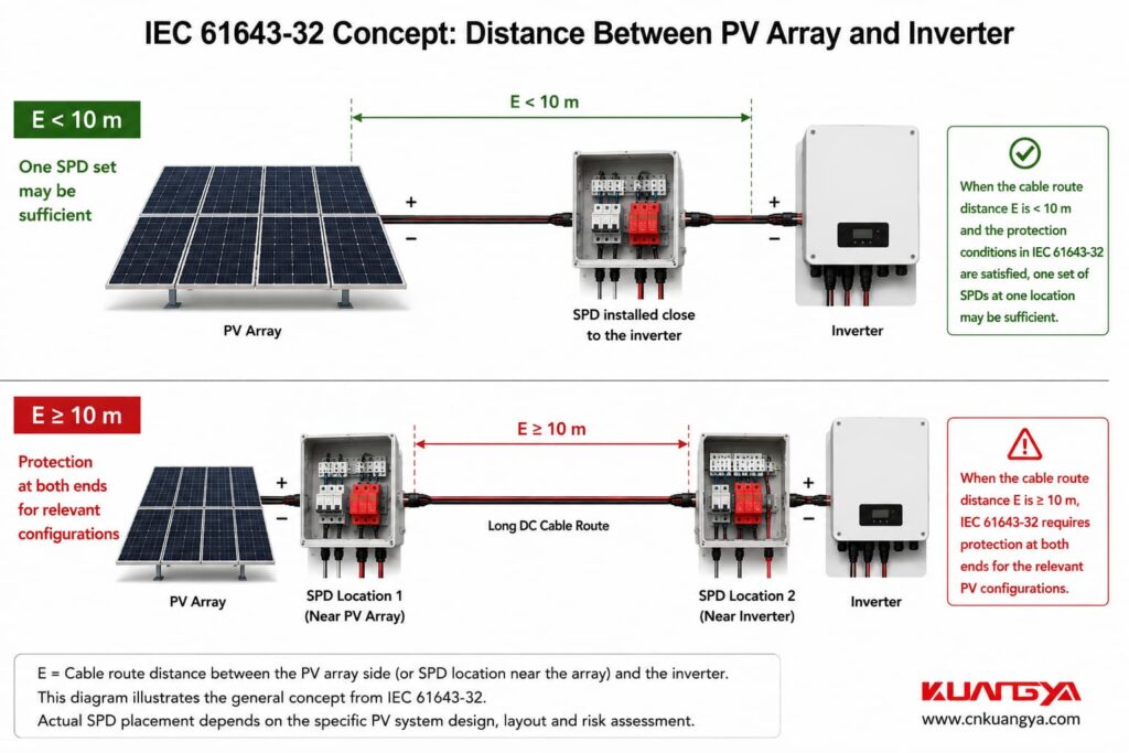
Cela signifie que la “ règle des 10 mètres ” souvent mentionnée n'est pas simplement une habitude industrielle.
Elle repose sur une base spécifique dans la norme IEC 61643-32.
Cependant, elle ne doit pas être transformée en une déclaration simpliste telle que :
“ Chaque installation solaire dans le monde nécessite automatiquement deux parafoudres dès que le câble atteint exactement 10 mètres. ”
Cela est également incorrect.
La norme IEC 61643-32 définit des configurations photovoltaïques spécifiques, et l'adoption nationale, les normes d'installation locales, les instructions des équipements, l'évaluation des risques et les conditions de protection contre la foudre doivent toujours être prises en compte.
Le contexte est important.
La norme IEC 61643-32 divise les installations photovoltaïques courantes en plusieurs configurations.
Il s'agit de la configuration décrite à l'article 6.2.1.
En général, la norme IEC illustre la protection à la fois côté onduleur et côté champ photovoltaïque, mais elle autorise l'omission de l'un des parafoudres DC sous certaines conditions spécifiées.
Par exemple, lorsque la distance entre l'onduleur et le champ photovoltaïque est inférieure à 10 m et que le niveau de protection en tension du parafoudre restant est correctement coordonné avec la tension de tenue aux chocs du champ photovoltaïque, le parafoudre supplémentaire peut ne pas être nécessaire.
La clause 6.2.2 concerne un bâtiment équipé d'un système de protection contre la foudre externe où la distance de séparation requise entre le SPF et l'installation photovoltaïque est maintenue.
Encore une fois, la norme CEI préconise généralement une protection aux deux extrémités, mais en autorise l'omission sous certaines conditions spécifiées.
Le principe des 10 m côté courant continu (DC) de la clause 9.2.5 s'applique également à cette configuration.
Il s'agit d'une condition plus sévère.
Lorsque la distance de séparation requise ne peut être maintenue, les composants photovoltaïques conducteurs peuvent faire partie du chemin du courant de foudre.
La norme CEI 61643-32 spécifie des parafoudres testés de classe I aux emplacements pertinents pour cette configuration, et la clause 9.2.5 note que le second parafoudre au niveau de l'onduleur est obligatoire pour le cas décrit en 6.2.3.
Si la différence entre la classe I, la classe II et la terminologie couramment utilisée de type 1, type 2 et type 1+2 n'est pas claire, consultez notre guide sur Classes et types de parafoudres CC.
Par conséquent :
Do not use distance alone to decide the SPD Type when an external lightning protection system is involved.
The LPS design and separation distance must be evaluated first.
This sentence is important.
IEC does pas say:
“If the PV cable is 9 meters long, one SPD is always enough.”
It says one set may be enough.
Pourquoi ?
Because distance is only one factor.
The SPD voltage protection level still has to be coordinated with the impulse withstand voltage of the equipment being protected.
IEC uses:
Uw = rated impulse withstand voltage of the equipment
et
Haut de la page = voltage protection level of the SPD.
For effective equipment protection, IEC 61643-32 states that Up must be lower than Uw and generally recommends maintaining at least a 20% safety margin:
subject to the applicable exceptions and coordination conditions.
So a short cable does not excuse poor SPD selection.
The SPD still has to be electrically suitable for the equipment.
For a broader selection workflow covering voltage rating, Up, discharge-current ratings and installation conditions, see comment dimensionner un parafoudre CC pour une installation photovoltaïque.
Consider two systems using exactly the same Type 2 DC SPD.
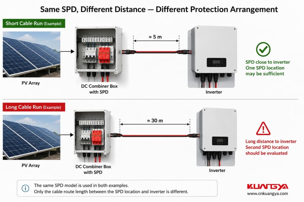
PV Array → 5 m DC Cable → SPD → Inverter
The SPD is close to the inverter.
PV Array → SPD → 30 m DC Cable → Inverter
Both systems contain one SPD.
But they should not automatically be treated as equivalent protection designs.
For the relevant IEC configurations, System B crosses the 10 m distance described in Clause 9.2.5, meaning protection at both ends must be considered according to the standard requirement.
The arrangement would typically become:
PV Array → SPD 1 → 30 m DC Cable → SPD 2 → Inverter
The exact SPD test class and ratings depend on the lightning protection condition and installation design.
Le point important est le suivant :
One SPD located somewhere on a long PV cable does not automatically provide sufficient coordinated protection at both ends.
In this situation, la distance du parafoudre par rapport à l'onduleur becomes particularly important because the protection device may be located at one end of a long DC cable.
This is one of the most common real-world situations.
A commercial PV system may look like:
Cordes PV
↓
Boîte combinée PV
↓
Long DC Cable
↓
Onduleur
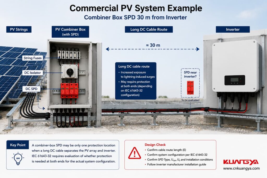
An installer opens the combiner box and sees a Type 2 SPD.
The natural question is:
“Why would I need another SPD? There is already one here.”
If the inverter is only a short distance away, the existing arrangement may satisfy the applicable protection requirements.
But if the cable route between the PV generator and inverter reaches the distance defined by IEC 61643-32, protection at both ends becomes relevant.
Phoenix Contact’s current PV application guidance follows the same basic arrangement: it identifies DC surge protection near the PV panels and DC protection near the inverter and specifically uses 10 m as the cable-distance criterion for the inverter-side location.
So the combiner-box SPD is not “wrong.”
It may simply represent only one protection location within a larger surge-protection concept.
Now the situation becomes more interesting.
Suppose the system is:
PV Array → External SPD → 25 m DC Cable → Inverter with Built-In Type 2 SPD
Potentially, you already have protection at both ends.
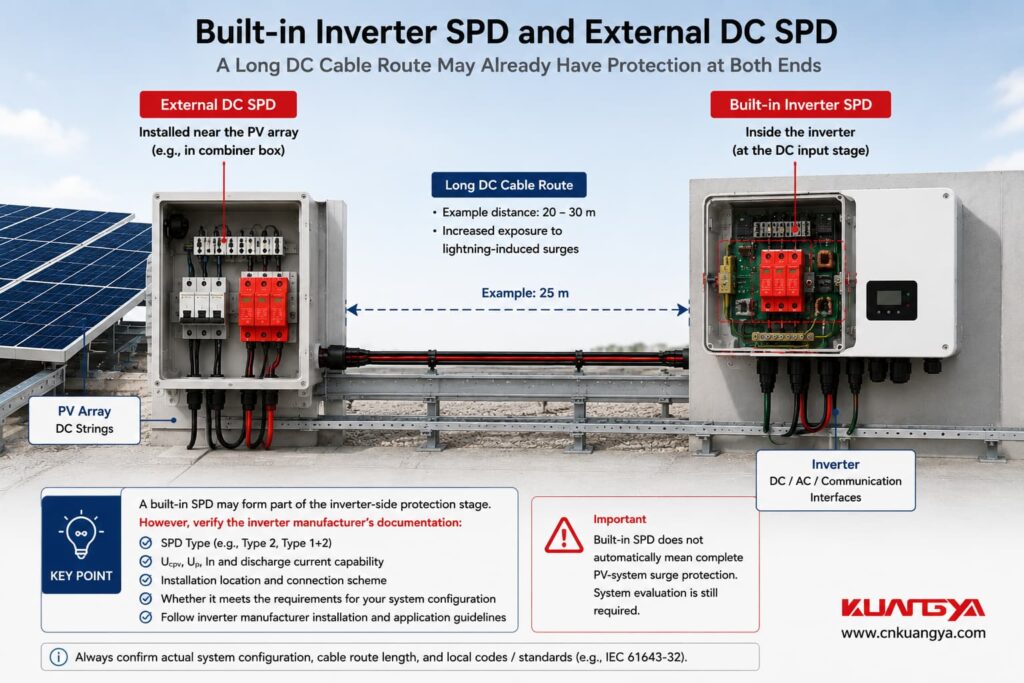
But you cannot confirm that from the words:
“Built-in SPD”
alone.
You need to check what is actually inside the inverter.
Important questions include:
A built-in SPD may form part of the inverter-side protection stage.
But:
Built-in SPD does not automatically mean complete PV-system surge protection.
If this is the situation in your system, read My Solar Inverter Already Has an SPD — Do I Still Need an External SPD? for a detailed explanation of when built-in and external protection may need to work together.
This is why SPD location and inverter documentation must be considered together.
Use this SPD distance from inverter checker to make a preliminary assessment of whether surge protection may be needed at both ends of a PV DC cable.
Now return to the second distance problem.
Even if your SPD is installed at exactly the correct system location, its wiring can still reduce protection performance.
Envisager :
DC conductor → short connection → SPD → short PE connection
et :
DC conductor → long loop → SPD → long loop → PE
The SPD model is identical.
Its datasheet Up is identical.
Its Imax is identical.
But the installed protection can be different.
Phoenix Contact explains that excessive SPD connection length raises the effective voltage protection level because of voltage developed across the conductor inductance. Its installation guidance references the 0.5 m connection-length principle and shows how conductor voltage has to be added to the SPD protection level when evaluating the complete installed protection.
IEC 61643-32 gives the same practical message for the DC side:
keep the SPD connecting cables as short as possible.
The 0.5 m figure should therefore be treated as a wiring target, not as a reason to mount an SPD exactly 500 mm from the inverter.
Enter the total relevant SPD connection lead length to check whether the wiring should be reviewed.
This is a practical installation check, not a pass/fail safety certification. The applicable wiring arrangement, relevant standards, and manufacturer instructions must also be considered.
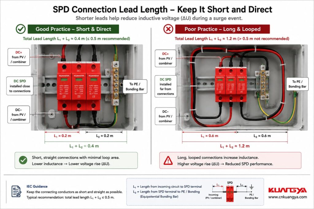
Suppose we use a simplified conductor inductance of:
L ≈ 1 µH/m
and a surge-current rise of:
10 kA in 10 µs
Then:
di/dt = 1 kA/µs
For one meter:
ΔU = L × di/dt
ΔU ≈ 1 µH × 1 kA/µs
ΔU ≈ 1 kV
This is the type of example Phoenix Contact uses to demonstrate why lead length matters.
But this should pas be turned into a calculator that claims:
“Every meter always adds exactly 1 kV.”
It does not.
Real values change with:
The calculation is best used to explain the physics, not to produce false precision.
Non.
Suppose one SPD has:
Imax = 40 kA
and another:
Imax = 80 kA
It is tempting to think:
“If my SPD is far from the inverter, I will simply install the 80 kA model.”
That does not solve the placement problem.
Imax describes the maximum discharge-current capability under the specified 8/20 µs test conditions.
It does not eliminate:
A higher Imax may be appropriate for some installations, but it is not a substitute for correct SPD placement.
Again, not by itself.
A lower Up can improve equipment protection because it means the SPD limits voltage to a lower level under its specified test conditions.
But the final installed protection depends on the complete circuit.
Par exemple :
Up = 2.0 kV
Very long connecting conductors
Up = 2.5 kV
Very short, direct connections
You cannot determine which installation produces the lower voltage at the equipment terminals from the SPD label alone.
The conductor voltage contribution also matters.
That is why SPD selection and SPD installation should never be treated as separate topics.
The physical cable route matters too.
Cable length is an easy number to measure, but electromagnetic behavior is influenced by geometry.
For surge currents, good practice includes:
IEC 61643-32 itself emphasizes minimizing loop areas in DC-side installation diagrams and recommends direct earthing between SPD and inverter for optimum overvoltage protection.
So two systems with the same “10 m cable length” are not necessarily electromagnetically identical.
An inverter is connected to more than one electrical system.
It has a DC input from the PV array and an AC connection to the distribution system.
IEC 61643-32 also addresses the AC side of the PV installation.
For the AC side, it recommends that where the wiring between the SPD near the origin of the electrical installation and the inverter is de 10 m ou plus, the inverter should be protected by an additional SPD adjacent to the inverter.
For the more severe external-LPS configuration described in Clause 6.2.3, the additional SPD at the inverter is mandatory.
Phoenix Contact’s current selection guidance follows the same basic structure, showing an additional AC-side SPD near the inverter when the cable length to the main distribution is 10 m or more.
Par conséquent :
A DC SPD does not replace AC surge protection.
Both electrical interfaces need to be assessed.
SPD placement is only one part of the overall protection architecture. For the relationship between SPDs, gPV fuses, DC isolators, combiner boxes and inverter protection, see our complete solar PV electrical protection guide.
Modern PV inverters may also be connected to:
These conductors can provide another path for transient overvoltages.
IEC 61643-32 states that when SPDs are required for the power circuits, surge protection should also be considered for telecommunications and signalling circuits associated with the PV system. Phoenix Contact makes the same practical recommendation for common inverter interfaces such as Ethernet and RS-485.
So an engineer reviewing inverter surge protection should ask:
“What conductors enter the inverter?”
not only:
“Where is the DC SPD?”
This is where simplified internet advice becomes especially risky.
If a building has an external lightning protection system (LPS), first determine whether the required separation distance s between the lightning protection system and the PV installation is maintained.
For the IEC configuration where the external LPS exists but separation distance is maintained, Class II tested PV SPDs are used at the relevant DC locations in the arrangement described by IEC 61643-32.
The 10 m DC-side placement principle still applies to the configuration covered by 6.2.2.
If separation distance cannot be maintained, parts of the PV system can carry partial lightning current.
This changes the required protection concept.
IEC 61643-32 specifies Class I tested SPDs at the relevant locations for this configuration, and the protection arrangement becomes more stringent.
This is why you should never decide:
“Type 2 is enough because the cable is only 8 meters.”
without first knowing the lightning protection condition.
Distance is only one part of the design.
PV Array → 6 m DC Cable → Inverter
No external LPS.
A suitable SPD is installed close to the inverter.
In this case, one set of DC SPDs may be sufficient if the applicable IEC conditions, Up coordination, equipment withstand voltage, and manufacturer instructions are satisfied.
The fact that the distance is below 10 m helps, but it is not the only requirement.
PV Array → Combiner Box + SPD → 25 m DC Cable → Inverter
For the relevant IEC 61643-32 configurations, the distance is ≥10 m.
Protection should therefore be provided at both ends in accordance with the standard arrangement.
A second suitable SPD close to the inverter is required for the configurations addressed by Clause 9.2.5.
PV Array → External SPD → 25 m DC Cable → Built-In SPD → Inverter
This may already resemble a two-location protection concept.
But the built-in device must be checked against:
Do not remove the external SPD simply because the inverter datasheet says “SPD included.”
PV Array → Inverter Cabinet
Inside the cabinet:
DC terminal → 80 cm wire → SPD → 70 cm PE wire
The system-level location may be good.
The SPD wiring is not.
The long connecting conductors can increase the installed protection level because of their inductive voltage.
In this case, the first fix is not necessarily another SPD.
It may be to redesign the connection.
Now cable distance alone is no longer the main issue.
The system has to account for partial lightning current, lightning equipotential bonding, SPD test class, and the complete LPS design.
This requires a lightning-protection-based SPD design rather than a simple “less than or greater than 10 m” decision.
| Situation | What IEC-Based Design Tells You to Check |
|---|---|
| PV array to inverter <10 m | One set may be sufficient, subject to protection-level conditions |
| PV array to inverter ≥10 m | Two sets necessary for relevant IEC 61643-32 configurations |
| External LPS, separation maintained | Apply the relevant 6.2.2 SPD arrangement |
| External LPS, separation not maintained | More stringent Class I/lightning-current protection applies |
| SPD leads approaching or exceeding 0.5 m | Review connection layout and installed protection level |
| SPD close to inverter | Still check Up, Ucpv, wiring, bonding and coordination |
| Inverter built-in SPD | Verify whether it satisfies the required inverter-side protection function |
| Long AC cable to main distribution | Additional AC-side SPD near inverter may be required/recommended |
| Communication lines entering inverter | Evaluate surge protection for signalling/data circuits |
An SPD protects according to its location, installation, and coordination with the rest of the system.
A device installed at one end of a long conductor should not automatically be assumed to provide the same protection at the other end.
Non.
The 10 m distinction appears directly in IEC 61643-32.
For the relevant DC-side configurations, ≥10 m leads to a two-SPD requirement for sufficient protection of both PV modules and inverter.
Also incorrect.
Below 10 m, IEC says one set may be sufficient.
Protection-level coordination and the rest of the installation still matter.
Non.
The 0.5 m guidance refers to the SPD’s relevant connecting conductors.
It is not the same measurement as the PV-array-to-inverter distance.
Non.
Imax does not compensate for long conductors, poor bonding, or incorrect protection location.
Not automatically.
Built-in protection has to be evaluated as part of the full PV protection concept.
The inverter also connects to AC and often to communication lines.
All possible surge-entry paths should be reviewed.
Before deciding that one SPD is enough, check:
Only after these points are understood should the designer decide whether an additional SPD is unnecessary, recommended, or required.
Oui.
The physical distance between protected parts of the PV system is specifically considered in IEC 61643-32, and long SPD connection leads can also increase the effective installed protection level.
These are two separate effects.
For PV installations covered by IEC 61643-32 Clauses 6.2.1 and 6.2.2, when the cable-route distance E between PV modules and inverter is equal to or greater than 10 m, Clause 9.2.5 requires two sets of SPDs to sufficiently protect both ends.
The exact SPD class and ratings still depend on the system and lightning protection arrangement.
Non.
IEC states that one set may be enough below 10 m.
The SPD voltage protection level, equipment impulse withstand voltage, installation arrangement, and other conditions still need to be satisfied.
IEC notes that common PV modules generally have a higher rated impulse withstand voltage than the inverter, and therefore recommends installing the SPD close to the inverter when one set is used.
For practical application, the relevant distance is the electrical cable-route distance between the units, not simply the straight-line distance measured through the air.
Non.
For the DC-side arrangement in IEC 61643-32 Clause 9.2.5, the 0.5 m recommendation refers to the total relevant SPD connecting leads, identified as L1 + L2 in the standard example.
Because the connecting conductors have inductance.
During a fast-rising surge current, the conductor develops an additional voltage:
ΔU = L × di/dt
This additional voltage contributes to the installed voltage appearing at the protected equipment.
Potentially, yes.
But its Type/test class, Ucpv, Up, protected circuit arrangement, installation, and manufacturer requirements must first be verified.
Do not assume all built-in SPDs are equivalent.
Non.
DC and AC are separate surge paths.
The AC-side protection arrangement must be evaluated separately.
First determine whether the required separation distance between the external LPS and PV installation is maintained.
If it is not maintained, IEC 61643-32 applies a more stringent lightning-current protection arrangement using Class I tested SPDs at the relevant locations.
Yes. SPD distance from inverter matters in solar PV surge protection design.
But there are two different distances that must not be confused.
The first is:
the cable-route distance between the PV array and inverter.
For the relevant IEC 61643-32 configurations:
E < 10 m
→ one set of SPDs may be sufficient if the required protection conditions are met.
E ≥ 10 m
→ two sets of SPDs are necessary to sufficiently protect both PV modules and inverter.
The second distance is:
the length of the SPD’s own connecting conductors.
These conductors should be kept as short as possible, with IEC 61643-32 giving a preferred total lead length of no more than approximately 0.5 m for the DC-side arrangement shown in Clause 9.2.5.
Neither rule should be used alone.
A technically sound PV surge-protection design also considers:
Up, Uw, Ucpv, SPD test class, lightning protection system, separation distance, bonding, earthing, cable routing, inverter built-in protection, AC-side protection, and SPD coordination.
The useful question is therefore not:
“How many SPDs does my solar system have?”
C'est :
“Are the SPDs positioned, selected, and connected so that every vulnerable part of the system receives the required protection?”
That is the difference between simply installing an SPD and designing a coordinated surge-protection system.
If you are unsure whether the existing SPD is far enough from the inverter to require another protection stage, send us:
KUANGYA can help you identify the SPD parameters and installation positions that should be checked before product selection.
You can also view our DC surge protective devices for solar PV systems for available Type 2 and Type 1+2 DC SPD options.
KUANGYA — Surge Protection for Solar PV Systems

