Zona industrial de WengYang Yueqing Wenzhou 325000
Horas de trabajo
De lunes a viernes: de 7.00 a 19.00 horas
Fin de semana: 10.00 A 17.00 HORAS
Zona industrial de WengYang Yueqing Wenzhou 325000
Horas de trabajo
De lunes a viernes: de 7.00 a 19.00 horas
Fin de semana: 10.00 A 17.00 HORAS

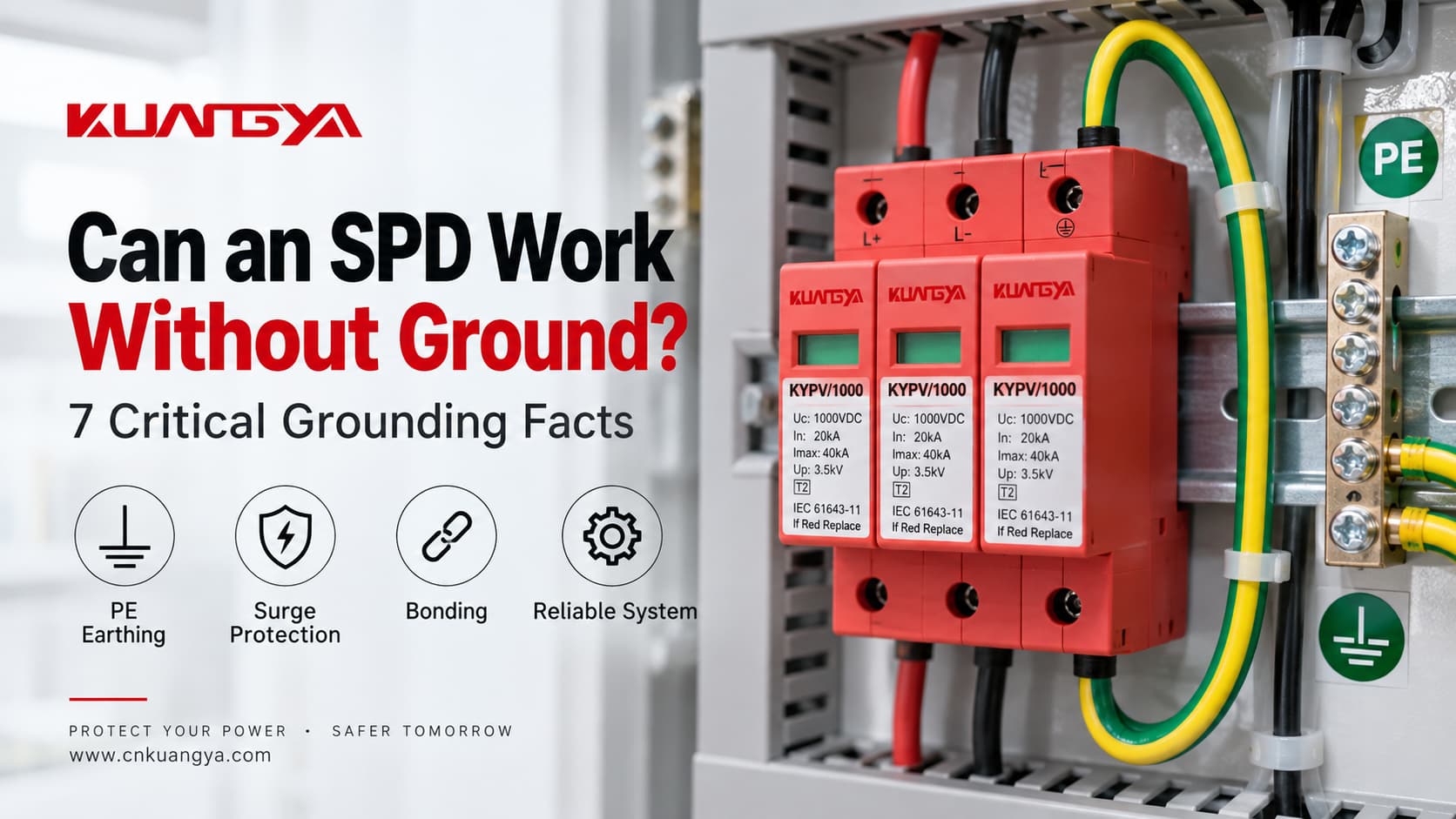
¿Puede un SPD funcionar sin tierra? La respuesta técnicamente correcta es: a veces, un modo de protección específico puede seguir funcionando sin una ruta directa a PE, pero eso no significa que el sistema completo de protección contra sobretensiones esté correctamente protegido sin una puesta a tierra o equipotencialidad.
Un dispositivo de protección contra sobretensiones no simplemente “envía cada sobretensión al suelo”. Limita la tensión entre conductores definidos al volverse conductor cuando la tensión a través de un modo de protección supera su región operativa. Dependiendo del diseño del SPD, esos modos de protección pueden incluir fase a neutro (L–N), fase a tierra de protección (L–PE), neutro a tierra de protección (N–PE), o CC+/CC− a PE.
Es por esto que la pregunta es más compleja que “¿conectado a tierra o no conectado a tierra?”. Las verdaderas cuestiones de ingeniería son:
Si el problema que intenta resolver no es la puesta a tierra, sino la diferencia entre un transitorio y un problema de tensión de mayor duración, lea primero ¿Protege un SPD contra sobretensiones?. La puesta a tierra no puede convertir un SPD en un regulador de tensión ni en un relé de sobretensión general.
¿Puede un SPD funcionar sin tierra? Una mejor respuesta es: depende de lo que signifique “tierra” y de qué modo de protección del SPD se esté tratando.
| Situación | ¿Puede el SPD hacer algo todavía? | Preocupación principal |
|---|---|---|
| Modo de protección L–N sin conexión directa a PE en ese modo | Potencialmente sí | Solo se limita la tensión en modo diferencial entre L y N |
| Modo de protección L–PE o N–PE con ausencia de PE | No conforme a lo previsto | La trayectoria de protección diseñada está incompleta o es incorrecta |
| Existe PE pero la conexión es excesivamente larga | El SPD aún podría operar | La tensión inductiva adicional puede aumentar el nivel de protección instalado |
| SPD incorrecto para el sistema de puesta a tierra TN/TT/IT | No asuma una protección correcta | Los modos de protección, el estrés por TOV y las condiciones de falla pueden no coincidir con el sistema |
| Sistema fotovoltaico de CC flotante | Sí, con una disposición de SPD fotovoltaico diseñada correctamente | “CC flotante” no significa que se pueda ignorar la PE y la conexión equipotencial |
| Conexión equipotencial ineficaz / conexión de PE dañada | La protección puede verse gravemente comprometida | Pueden permanecer diferencias de potencial entre sistemas conductores |
La regla más importante es:
No decida si un SPD “necesita tierra” mirando solo el número de módulos. Identifique el esquema de conexión a tierra del sistema y los modos de protección reales del SPD.
Esta es la misma razón por la que un SPD fotovoltaico de 2P o 3P no debe seleccionarse solo por su apariencia. Nuestra Guía comparativa de SPD de CC de 2P frente a 3P explica por qué el número de módulos, los conductores protegidos, la conexión a tierra (PE) y las rutas de protección interna son conceptos diferentes.
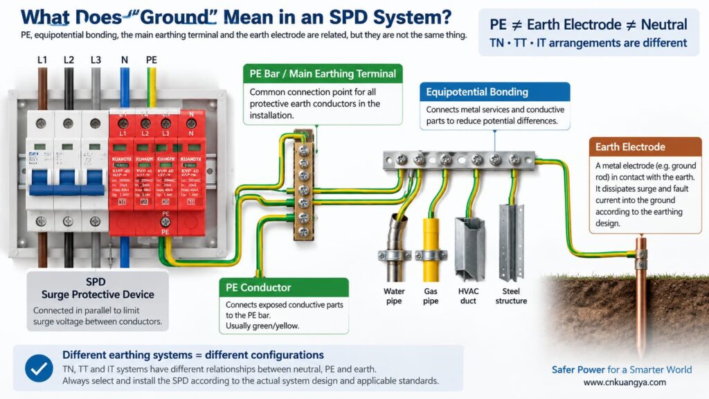
Antes de responder “¿puede un SPD funcionar sin tierra?”, primero debemos definir qué significa realmente “tierra” en una instalación eléctrica.
En la conversación cotidiana, “tierra” puede referirse a varias cosas diferentes:
PE es el conductor de protección utilizado para conectar las partes conductoras expuestas y el sistema de conexión equipotencial de la instalación eléctrica. Muchos SPD de potencia incluyen modos de protección que toman como referencia a PE.
Este es el punto de conexión dentro del conjunto de instalación o distribución donde se conectan los conductores de protección de acuerdo con el diseño del sistema.
Un electrodo de puesta a tierra proporciona una conexión conductora entre la instalación eléctrica y la tierra. Es parte del sistema de puesta a tierra, pero no debe confundirse con la conexión PE corta entre un SPD y la barra PE local.
La conexión reduce las diferencias de tensión peligrosas entre las partes conductoras y los servicios. Durante un evento de sobretensión, controlar las diferencias de potencial suele ser más importante que imaginar que la corriente de sobretensión sigue un camino simple “hacia un cable de tierra”.”
La relación entre el neutro y la tierra depende del sistema de puesta a tierra. Los sistemas TN, TT e IT no utilizan la misma disposición de neutro/PE, lo cual es una razón por la que no se debe asumir que la misma topología de SPD es adecuada en todas partes.
La guía práctica de SPD de ABB distingue los sistemas de puesta a tierra TT, TN-C, TN-S y TN-C-S según cómo se relacionan el neutro de alimentación y las tierras de los equipos. Por lo tanto, la selección del SPD debe coordinarse con el sistema eléctrico real en lugar de basarse en una regla universal de “cable de tierra”.
Un SPD de potencia típico se conecta en paralelo con el circuito en lugar de transportar la corriente de carga normal en serie. En condiciones normales, sus elementos de protección contra sobretensiones permanecen en un estado de alta impedancia. Cuando la tensión a través de un modo de protección aumenta lo suficiente, el SPD se vuelve conductor y limita la tensión desviando la corriente de sobretensión a través de esa ruta de protección.
Si desea primero la explicación a nivel de circuito, consulte por qué un SPD se conecta en paralelo en lugar de en serie.
La frase “desviar la corriente de sobretensión a tierra” es útil como explicación simplificada, pero también puede generar un malentendido. No todas las sobretensiones son gestionadas por un único conductor que va directamente a una varilla de puesta a tierra.
Considere tres modos de protección comunes:
| Modo de protección | Tensión que está siendo limitada | ¿Este modo utiliza directamente PE? |
|---|---|---|
| L–N | Fase respecto a neutro | No se requiere un terminal PE directo para ese modo individual |
| L–PE | Fase respecto a tierra de protección | Sí |
| N–PE | Neutro respecto a tierra de protección | Sí |
| CC+–PE / CC−–PE | Conductores fotovoltaicos en relación con PE | Sí |
Esta es la clave para entender la pregunta.
Un elemento de protección L–N aún puede limitar la tensión diferencial entre fase y neutro, aunque ese elemento específico no esté conectado directamente a PE. Sin embargo, si la instalación también requiere protección contra sobretensiones en modo común respecto a PE, una trayectoria L–N por sí sola no sustituye los modos de protección requeridos relacionados con PE ni el sistema de equipotencialidad.
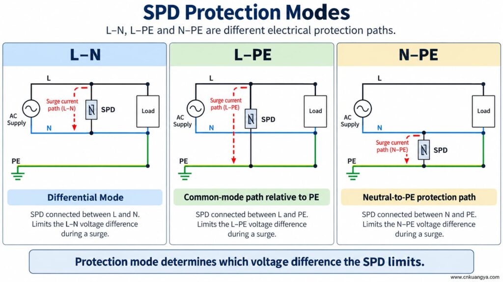
¿Puede un SPD funcionar sin tierra o PE? Si el SPD solo tiene un modo de protección entre conductores activos, ese modo aún puede responder a una diferencia de tensión entre dichos conductores. Pero un modo de protección dependiente de PE no puede funcionar según lo diseñado si falta su conexión a PE.
Eso significa que ambas afirmaciones pueden ser ciertas:
Por lo tanto, nunca elimine, puentee ni improvise la conexión PE simplemente porque un SPD muestre un indicador de estado en verde.
La ventana de estado normalmente informa sobre la condición de un mecanismo interno monitoreado. No garantiza que el conductor PE externo exista, que el sistema de conexión equipotencial sea correcto o que la longitud de la conexión sea aceptable.
Si un SPD está diseñado con rutas de protección L-PE, N-PE, DC+-PE o DC--PE y la conexión PE queda abierta, esos modos dejan de tener la conexión externa prevista.
Las posibles consecuencias incluyen:
La falta de un conductor de protección no es un atajo para la resolución de problemas de un SPD. La instalación debe ser inspeccionada y corregida por una persona cualificada de acuerdo con las instrucciones del equipo y las normas eléctricas aplicables.
La respuesta a “¿puede un SPD funcionar sin tierra?” cambia porque la arquitectura de puesta a tierra varía en los sistemas TN, TT e IT.
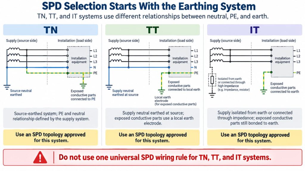
En una configuración TN-S, el neutro y el conductor de protección (PE) son conductores separados en la instalación. El SPD debe seleccionarse y conectarse según la configuración del sistema y los modos de protección correspondientes.
In TN-C-S systems, the upstream PEN conductor is divided into separate N and PE at a defined point. An SPD installed on the TN-S part must be suitable for that part of the system. The exact connection arrangement should follow the product instructions and local requirements.
Do not create an extra neutral-to-earth link beside the SPD as an improvised “better ground.” Neutral/PE bonding is a system-design issue, not a field modification to improve SPD performance.
In a TT system, the installation’s exposed conductive parts are connected to a local earth electrode while the supply neutral has its own source earthing arrangement.
This affects SPD topology, protection modes, temporary overvoltage behavior, and coordination with protective devices. Depending on the design, manufacturers often provide specific TT-compatible SPD arrangements rather than treating a TN model as universally interchangeable.
The correct question is therefore not “Does TT have a ground rod?” but:
Is this SPD and its connection arrangement specifically suitable for the TT system at this installation point?
In an IT system, the supply may be isolated from earth or connected to earth through an impedance, while exposed conductive parts remain earthed according to the installation design.
This creates different voltage conditions, especially during a first insulation fault. An SPD used in an IT system must therefore be explicitly suitable for that system and for the possible continuous and temporary voltages it can experience.
Do not choose an SPD for an IT system solely because its Uc value appears high enough.
For AC SPDs, IEC 61643-11:2025 specifies performance and safety requirements for SPDs connected to AC low-voltage power systems. System selection and installation still require coordination with the actual network and installation rules. See the IEC 61643-11:2025 publication page.
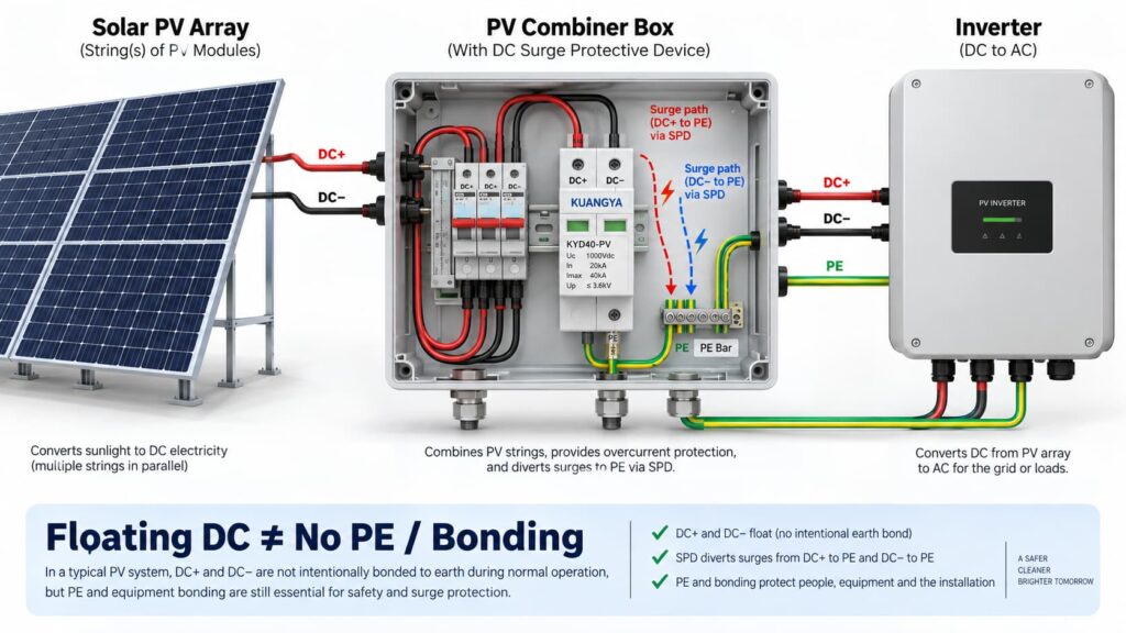
In solar PV systems, the question “can an SPD work without ground?” becomes even more complicated because the DC circuit may be intentionally floating.
Many PV DC circuits operate with neither DC+ nor DC− intentionally bonded directly to earth during normal operation. This is often described as a floating or unearthed DC array.
But that does no mean the whole PV installation has no protective earth, bonding or surge path to PE.
A PV SPD may provide coordinated protection between:
Some PV SPDs use a Y-type internal circuit specifically intended for photovoltaic applications. The correct arrangement depends on the inverter topology, PV earthing arrangement, maximum PV voltage, insulation-monitoring concept and the manufacturer’s approved circuit.
This is why a floating PV system can still use a PE-connected SPD arrangement.
IEC 61643-31 applies to SPDs intended for the DC side of photovoltaic installations up to 1500 V DC and covers their performance characteristics, safety requirements, test methods and ratings. See the IEC 61643-31 publication page.
Before selecting a PV SPD, also verify Ucpv, In, Imax, Up and Iscpv. Our Guía de especificaciones de SPD de CC explains what these markings mean and why the largest kA number is not enough.
No.
A 2P or 3P description does not automatically tell you:
For the same reason, AC module count can also be misleading. If you are comparing neutral/PE arrangements, see our Comparativa de SPD 3+1 frente a 4+0.
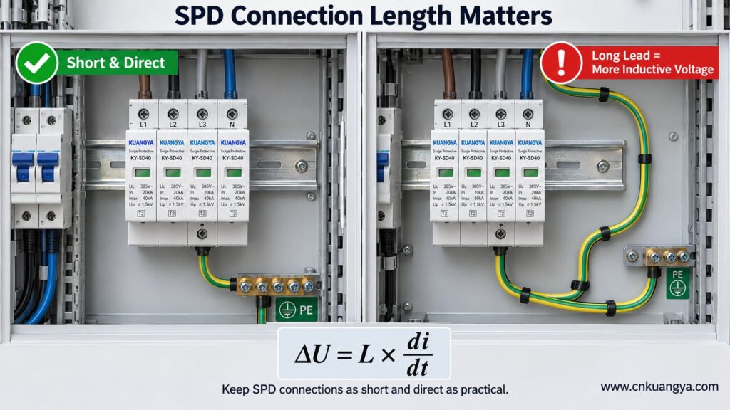
An SPD can be correctly selected and correctly connected to PE, yet still provide poorer installed protection because the connection conductors are too long.
The reason is conductor inductance.
During a fast-rising surge current, additional voltage develops across the SPD connecting conductors:
ΔU = L × di/dt
Donde:
This means the equipment does not necessarily see only the SPD’s datasheet voltage protection level Up. The installed voltage can also include voltage developed across the connection path.
Schneider Electric’s Electrical Installation Guide recommends keeping the total SPD connection length to the network and earth terminal block at no more than approximately 50 cm in the illustrated arrangement and explains the added inductive voltage created by longer conductors. See its SPD connection guidance.
The current consolidated IEC installation standard is IEC 60364-5-53:2019 + Amendment 1:2020 + Amendment 2:2024, which includes Clause 534 for surge protective devices. See the IEC 60364-5-53 consolidated publication page.
If you want a deeper explanation of why conductor length matters during a surge, read our guide on SPD distance from the inverter and connection lead length.
So when asking whether an SPD can work without ground, the quality and length of the PE connection are just as important as whether a protective-earth conductor is physically present.
Trying to reduce lead length by bypassing the approved panel bonding arrangement and connecting an SPD to a separate, isolated earth electrode can create a different problem: the installation may no longer be equipotentially bonded as required.
The correct objective is not “find the nearest piece of earth.”
Es:
Connect the SPD to the manufacturer-specified PE/bonding point using the shortest practical, low-impedance path permitted by the system design.
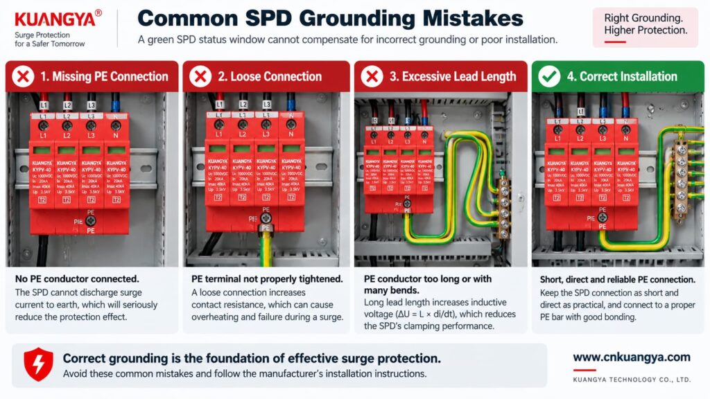
Poor grounding is not one single failure mode. The effect depends on what is actually wrong.
| Problema | Possible Effect | Qué comprobar |
|---|---|---|
| PE conductor missing | PE-dependent protection modes may not function as intended | Wiring diagram, PE continuity, bonding arrangement |
| Loose PE terminal | Unstable/high-impedance surge path, heating or arcing risk under fault conditions | Terminal condition and specified torque |
| Very long SPD connection | Higher installed residual voltage due to inductive voltage | Lead length and routing |
| Large conductor loop | Higher inductive coupling and loop impedance | Routing and loop area |
| Wrong TN/TT/IT SPD topology | Incorrect protection modes or unsuitable voltage stress | System earthing arrangement and manufacturer approval |
| Unbonded conductive systems | Dangerous transient potential differences may remain | Equipotential bonding of incoming services and installation |
| Green SPD indicator but external wiring fault | False confidence | Inspect the complete installation, not only the indicator |
Not by itself.
This is another important distinction.
A low measured earth-electrode resistance can be useful for the earthing system, but SPD performance during a fast transient also depends heavily on:
Therefore, a long conductor to an excellent earth electrode can still develop significant transient voltage during a steep surge current.
For surge protection, think in terms of impedance and equipotential bonding, not only DC or low-frequency resistance.
Can an SPD work without ground when it only protects L–N? It may limit the voltage between L and N if that is an approved protection mode of the device.
However, three cautions are essential.
If a surge raises both L and N relative to PE, an L–N element may see relatively little differential voltage even though the equipment is experiencing a large common-mode voltage relative to earth.
Electronic equipment can have chassis connections, signal cables, communication ports, antennas, shields or other conductive interfaces that create additional surge paths.
Do not intentionally leave a PE terminal disconnected on an SPD that is designed to use it. The correct wiring diagram is part of the product’s protection concept.
A backup fuse or circuit breaker does not replace grounding.
Likewise, grounding does not replace backup overcurrent protection where the SPD manufacturer requires it.
| Component / Function | Main Role |
|---|---|
| SPD | Limits transient overvoltage and diverts surge current through defined protection modes |
| PE / bonding system | Provides protective bonding and reference/discharge paths according to the installation design |
| Backup fuse or circuit breaker | Helps isolate fault current according to the SPD manufacturer’s coordination requirements |
| Earth electrode | Connects the installation earthing system to earth |
| Voltage protection relay / regulator | Addresses longer-duration abnormal voltage depending on device type |
If you are selecting upstream protection, see our practical guide: does an SPD need a backup fuse or circuit breaker?
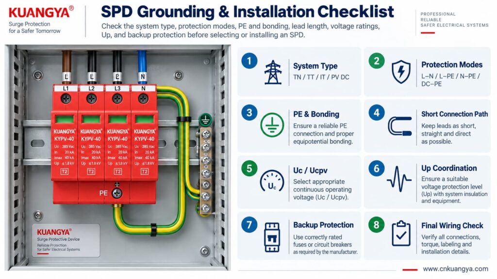
Use the following sequence as a design and inspection checklist. It is not a substitute for local electrical rules or the manufacturer’s instructions.
Confirm whether the circuit is:
Read the internal circuit or wiring diagram, not only the product front label.
Look for protection paths such as L–N, L–PE, N–PE, L1/L2/L3 relationships, DC+–PE and DC−–PE.
Connect only to the approved PE or bonding terminal shown by the manufacturer and installation design.
Avoid unnecessary conductor loops, coils and wide separation between surge-current paths.
For AC, confirm Uc and the applicable system voltage. For PV, confirm Ucpv against the maximum possible PV voltage, including cold-weather Voc where relevant.
Remember that installed protection depends on both the SPD’s Up and the voltage contribution of the connecting conductors.
Verify the manufacturer’s maximum backup fuse / circuit-breaker requirements and the prospective short-circuit conditions.
If an inverter already contains an SPD, do not assume external surge protection is unnecessary. Cable distance, system architecture and the location of the built-in SPD still matter. See our guide on solar inverter built-in SPD and external SPD requirements.
Before deciding whether an SPD can work without ground in a real installation, check the complete protection system rather than judging the SPD alone.
| Consulte | Pregunta | Por qué es importante |
|---|---|---|
| Sistema | TN, TT, IT, AC or PV DC? | Determines compatible SPD topology |
| Modos de protección | Which conductor pairs are protected? | Shows what voltage differences the SPD can limit |
| Conexión PE | Is PE required and correctly connected? | Essential for PE-dependent protection modes |
| Bonding | Are relevant conductive systems equipotentially bonded? | Reduces dangerous transient potential differences |
| Lead length | Are SPD connections as short and direct as practical? | Reduces added inductive voltage |
| Tensión | Is Uc / Ucpv correct? | Avoids continuous overvoltage stress |
| Protection level | Is Up coordinated with the equipment? | Determines residual voltage stress |
| Surge rating | Are In, Imax and/or Iimp suitable? | Matches expected surge duty |
| Short-circuit conditions | Are SCCR / Iscpv and backup protection suitable? | Important for safe failure and isolation |
| Manufacturer diagram | Does the installed wiring match the approved circuit? | Prevents topology mistakes |
For photovoltaic projects, KUANGYA provides Dispositivos de protección contra sobretensiones de CC for different PV voltage classes and installation requirements. Final model selection should always be based on the actual PV voltage, earthing arrangement, protection mode, SPD type and system fault conditions.
Sometimes an individual protection mode such as L–N can operate without a direct PE connection. However, that does not mean the complete surge-protection system can ignore PE, earthing or equipotential bonding. Any SPD mode designed to operate between a live conductor and PE requires the intended PE connection.
When people ask “can an SPD work without ground?”, the answer depends on the SPD circuit rather than on one universal rule. Some devices or protection modes operate only between active conductors, while many power SPDs include PE-related protection modes. Follow the manufacturer’s circuit diagram and select the SPD for the actual TN, TT, IT or DC/PV system.
The SPD may still operate, but a long connection can add inductive voltage during a fast-rising surge current. This can increase the voltage that appears at the protected equipment. Short, direct connections are therefore an important part of SPD installation.
Do not improvise an isolated grounding path simply to make the SPD conductor shorter. The SPD should be connected to the approved PE/bonding point in accordance with the system design, manufacturer instructions and applicable electrical rules.
Not by itself. Surge performance also depends on high-frequency impedance, connection length, conductor routing, loop area, bonding and the SPD’s protection characteristics. A low earth-electrode resistance does not compensate for poor SPD wiring.
Yes. A PV DC system may have neither polarity intentionally grounded during normal operation while still using a properly designed SPD arrangement with protection paths to PE. Use a PV SPD approved for that topology and voltage.
No. A status indicator normally reports the condition of the SPD’s internal monitoring or disconnection mechanism. It does not verify external PE continuity, bonding, conductor length or correct earthing-system selection.
No. An SPD and the installation’s protective-earthing/bonding system perform different functions. A surge protective device should be considered part of a coordinated electrical protection system, not a replacement for protective earthing.
Grounding and bonding are fundamental parts of electrical safety and lightning/surge protection, but they do not perform the same voltage-limiting function as an SPD at equipment terminals. A complete design may require both, depending on the installation.
There is no single standard that answers every installation question. IEC 61643-11 covers AC low-voltage SPD product requirements, IEC 61643-31 covers PV DC SPD product requirements, and IEC 60364-5-53 includes installation requirements for low-voltage electrical installations, including Clause 534 for SPDs. Project-specific lightning-protection and national wiring requirements may also apply.
¿Puede un SPD funcionar sin tierra? The answer cannot be reduced to a simple yes or no.
An SPD limits voltage across specific protection modes. A mode between active conductors, such as L–N, may operate without directly using PE. But any protection mode that depends on L–PE, N–PE, DC+–PE or DC−–PE requires the designed PE/bonding path.
More importantly, surge protection is a system function.
A correctly selected SPD can still perform poorly if:
For that reason, do not ask only:
“Does this SPD have a ground terminal?”
Ask instead:
“What voltage differences must be limited, what protection modes does this SPD provide, and how is the complete system bonded and earthed?”
That question leads to a much safer and more technically correct SPD selection.
Technical note: This article is intended for product selection and engineering education. Actual SPD installation must follow the device manufacturer’s wiring instructions, the applicable electrical installation standard, and local code requirements.

