Zona industrial de WengYang Yueqing Wenzhou 325000
Horas de trabajo
De lunes a viernes: de 7.00 a 19.00 horas
Fin de semana: 10.00 A 17.00 HORAS
Zona industrial de WengYang Yueqing Wenzhou 325000
Horas de trabajo
De lunes a viernes: de 7.00 a 19.00 horas
Fin de semana: 10.00 A 17.00 HORAS

Un dispositivo de protección contra sobretensiones protege los equipos eléctricos de sobretensiones transitorias, pero ¿qué protege al SPD si ocurre una falla interna o un cortocircuito?
Aquí es donde el fusible de respaldo o disyuntor del SPD cobra importancia.
Sin embargo, no existe una regla universal como:
“Todo SPD de Tipo 2 necesita un fusible de 125 A”.”
o:
“Un SPD de 40 kA debe utilizar un interruptor de 40 A.”
Ambas afirmaciones pueden ser incorrectas.
Correcto Fusible de respaldo para SPD La selección depende del modelo exacto de SPD, la protección contra sobrecorriente aguas arriba, la corriente de cortocircuito prospectiva, el tamaño del conductor, la configuración del sistema y las instrucciones del fabricante.
Algunos SPD pueden utilizar el fusible o interruptor automático existente aguas arriba. Otros requieren una protección de respaldo independiente. Algunos productos incluso integran la protección de respaldo dentro del propio SPD.
Por lo tanto, la regla más importante es sencilla:
No seleccione un fusible de respaldo para SPD basándose únicamente en la clasificación In, Imax o el tipo de SPD. Compruebe siempre la protección de respaldo declarada por el fabricante y las condiciones reales de instalación.
Un SPD puede necesitar un fusible de respaldo o un interruptor automático, pero no todas las instalaciones requieren uno independiente.
Si el dispositivo de protección contra sobrecorriente aguas arriba existente ya cumple con la configuración de protección permitida por el fabricante del SPD, es posible que no se requiera un fusible de respaldo adicional.
Si el dispositivo de protección aguas arriba excede el valor permitido por el fabricante, o si las instrucciones del SPD especifican una protección de derivación dedicada, un fusible de respaldo o disyuntor del SPD adicional puede ser necesario.
Esto significa que la pregunta correcta no es simplemente:
“¿Qué tamaño de fusible debo instalar?”
En su lugar, pregunte:
“¿La protección aguas arriba existente ya cumple con los requisitos de este SPD específico?”
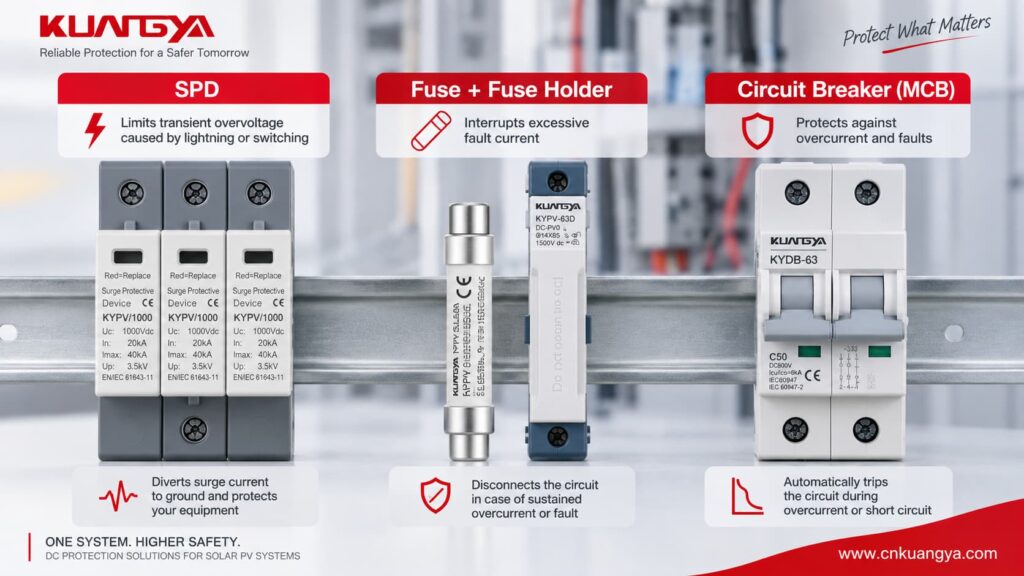
Un SPD y un dispositivo de protección contra sobrecorriente resuelven problemas eléctricos diferentes.
Un SPD de potencia típico se conecta en paralelo con el circuito.
Durante el funcionamiento normal, transporta poca o ninguna corriente de carga normal. Cuando ocurre una sobretensión transitoria, el SPD se vuelve conductor y desvía la corriente de sobretensión a través de su trayectoria de protección diseñada.
Un fusible o un interruptor automático tienen un propósito diferente.
Su función principal es interrumpir la sobrecorriente sostenida o la corriente de falla.
| Dispositivo | Función principal | Diseñado principalmente para |
|---|---|---|
| SPD | Limita la sobretensión transitoria y deriva la corriente de sobretensión | Transitorios por rayos y maniobras de conmutación |
| Fusible | Interrumpe el exceso de corriente | Sobrecorriente y cortocircuito |
| Interruptor automático | Interrumpe el exceso de corriente y proporciona aislamiento/conmutación | Sobrecarga y cortocircuito |
| Desconectador interno de SPD | Desconecta un elemento de protección averiado o sobrecalentado | Fin de vida útil del SPD o condición interna anormal |
Por lo tanto:
SPD ≠ fusible
y:
Fusible ≠ SPD
Proporcionan una protección complementaria.
Muchos dispositivos de protección contra sobretensiones (SPD) limitadores de tensión utilizan componentes no lineales como varistores de óxido metálico.
Durante la tensión normal del sistema, el elemento de protección permanece en alta impedancia.
Durante una sobretensión, su comportamiento eléctrico cambia rápidamente y conduce la corriente de sobretensión.
Sin embargo, los componentes de protección contra sobretensiones pueden llegar eventualmente al final de su vida útil o dañarse debido a:
Si un elemento de protección desarrolla un fallo de baja impedancia, la instalación debe ser capaz de desconectar de forma segura la corriente de fallo resultante, ya sea a frecuencia industrial o en corriente continua.
Es por esto que las hojas de datos de los SPD pueden incluir parámetros tales como:
Para los SPD de baja tensión en CA, la norma internacional de producto actual es CEI 61643-11:2025, que cubre los requisitos y métodos de ensayo para SPD conectados a circuitos de CA de hasta 1.000 V RMS.
IEC 61643-11:2025 — página oficial de la IEC
Una pregunta común es:
“Si mi SPD ya tiene un desconectador interno, ¿por qué necesitaría otro fusible?”
Porque no necesariamente realizan la misma función.
El desconectador interno generalmente está asociado con el componente de protección contra sobretensiones dentro del SPD.
Por ejemplo, cuando un MOV alcanza una condición térmica insegura, el mecanismo interno puede desconectar el elemento fallido.
En muchos SPD modulares, esta condición está vinculada mecánicamente a un indicador de estado.
La ventana puede cambiar de verde a rojo, dependiendo del diseño del fabricante.
El fusible o disyuntor externo es parte de la protección contra corrientes de falla y la coordinación de la instalación.
Dependiendo del SPD, puede ayudar a:
Por lo tanto:
Un desconectador térmico interno no debe considerarse automáticamente como un reemplazo para un fusible de respaldo externo del SPD.
La documentación del producto debe consultarse en cualquier caso.
No.
Existen tres situaciones comunes.
| Condición de instalación | Protección de respaldo independiente |
|---|---|
| El dispositivo aguas arriba existente cumple con las condiciones permitidas por el fabricante del SPD | A menudo no es necesario |
| El dispositivo aguas arriba existente excede el límite permitido por el fabricante | Puede requerirse una protección dedicada |
| El SPD cuenta con protección de respaldo integrada probada | Es posible que no se requiera un dispositivo de respaldo adicional bajo condiciones específicas |
Este es uno de los puntos más importantes en Protección de respaldo para SPD.
No puede tomar la decisión utilizando solo:
Dos SPD de Tipo 2 con tensiones e intensidades máximas (Imax) similares pueden tener requisitos de protección de respaldo diferentes.
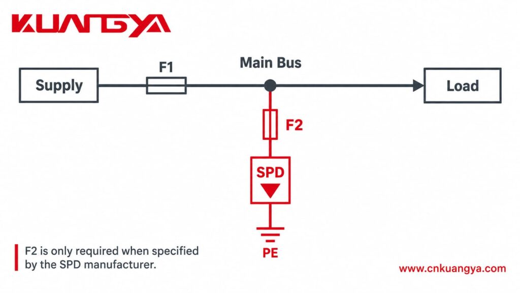
Los diagramas de instalación de SPD suelen utilizar dos designaciones:
F1 = dispositivo de protección del sistema aguas arriba
F2 = dispositivo de protección de respaldo dedicado para el SPD
Una disposición simplificada puede verse así:
Suministro → F1 → Sistema de distribución
con el SPD conectado en paralelo a través de F2 donde se requiere protección F2 dedicada.
Al seleccionar un Fusible de respaldo para SPD, la primera pregunta no debería ser, por tanto:
“¿Qué tamaño de fusible debo comprar?”
En su lugar, pregunte:
“¿Puede el F1 existente proporcionar ya la protección requerida por este SPD?”
Si F1 cumple con las condiciones del fabricante, F2 podría no ser necesario.
Si F1 es mayor que el valor permitido, podría ser necesario un F2 dedicado.
Este principio se demuestra claramente en varias guías de instalación publicadas por los fabricantes, las cuales examinaremos más adelante.
No existe un tamaño Fusible de respaldo para SPD universal.
Comience siempre con la hoja de datos o las instrucciones de instalación exactas del fabricante.
Busque términos como:
No tome el valor de un fusible de otro SPD simplemente porque ambos dispositivos sean de Tipo 2 o ambos tengan Imax = 40 kA.
La construcción del producto y la coordinación probada pueden ser diferentes.
Suponga que un fabricante de SPD permite:
Protección máxima aguas arriba = 125 A gG
y el sistema ya cuenta con:
F1 = 63 A gG
Si se cumplen todos los demás requisitos del fabricante, el fusible aguas arriba existente ya podría proporcionar la protección necesaria.
Instalar otro fusible de 125 A no hace que la instalación sea automáticamente más segura.
Ahora considere:
F1 = 250 A gG
Si el SPD solo está aprobado con una configuración de respaldo de un máximo de 125 A gG, la protección existente de 250 A podría dejar de cumplir con los requisitos del SPD.
Un dispositivo dedicado Fusible de respaldo para SPD podría ser necesario entonces.
Es por esto que F1 debe verificarse antes de añadir F2.
El amperaje nominal del fusible por sí solo no es suficiente.
También debe considerar la corriente de falla disponible en el punto de instalación.
El mismo SPD puede enfrentar condiciones de falla muy diferentes dependiendo de dónde esté instalado.
Por ejemplo:
Un cuadro de distribución pequeño aguas abajo puede tener una corriente de cortocircuito prospectiva relativamente baja.
Un panel industrial principal cerca de un transformador puede tener una corriente de falla disponible significativamente mayor.
Por lo tanto, evalúe siempre la combinación de:
SPD + protección de respaldo + corriente de cortocircuito disponible
Esto es especialmente importante en:
Considere un SPD de Tipo 2 marcado como:
In = 20 kA
Imax = 40 kA
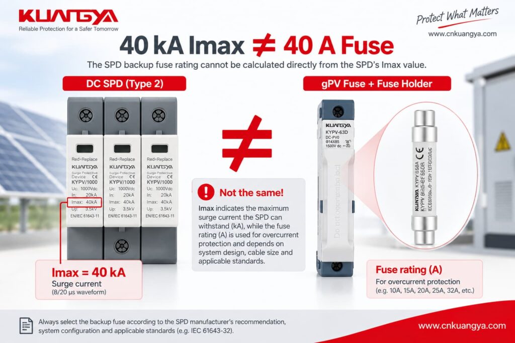
Un error muy común es:
“El SPD es de 40 kA, por lo que debería usar un fusible de 40 A.”
Eso es incorrecto.
Imax = 40 kA describe una característica de corriente de descarga asociada con la forma de onda de impulso relevante.
A fusible de 40 A es una clasificación de dispositivo de protección contra sobrecorriente.
Estos valores describen fenómenos eléctricos diferentes.
Por lo tanto:
La clasificación del fusible de respaldo del SPD no puede calcularse directamente a partir del valor Imax del SPD.
Si no está seguro acerca de la diferencia entre In, Imax, Up e Iscpv, consulte nuestro Guía de especificaciones de SPD de CC.
Comprender estos parámetros evita uno de los errores más comunes en la selección de SPD.
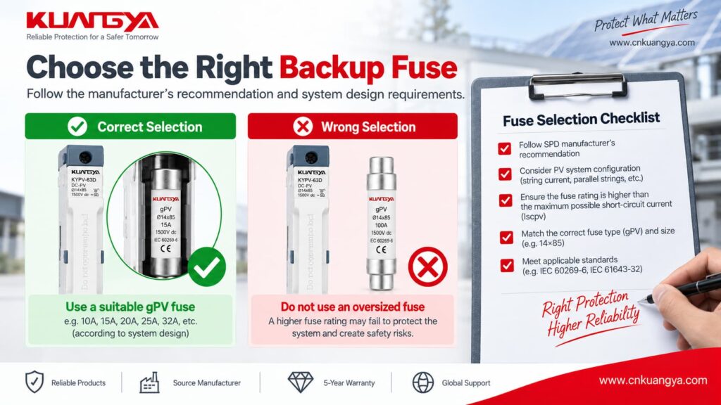
El valor máximo de fusible de respaldo del fabricante no significa que siempre deba instalarse el fusible más grande permitido.
El dispositivo de protección también debe coordinarse con:
For example, if an SPD permits a maximum backup fuse of 125 A, that does not automatically mean every installation should use a 125 A fuse.
Maximum is a limit, not always a recommendation.
A fuse and a circuit breaker can both provide overcurrent protection, but their operating characteristics are different.
| Factor | Fusible | Interruptor automático |
|---|---|---|
| Replacement after operation | Must normally be replaced | Can normally be reset after investigation |
| Time-current behavior | Depends on fuse class and rating | Depends on breaker type and trip curve |
| Short-circuit capability | Can be very high | Depends on breaker breaking capacity |
| Surge impulse behavior | Depends on fuse characteristics | Depends on breaker characteristics |
| Aislamiento | Requires suitable holder/switching arrangement | Often convenient |
| Coordinación | Must match SPD data | Must match SPD data |
Por lo tanto:
Do not assume that a 125 A gG fuse can automatically be replaced by a 125 A circuit breaker.
Manufacturers can specify different protective-device combinations.
For example, Schneider Electric publishes coordination tables pairing particular SPD models with specific protective-device ratings rather than applying one universal breaker value.
Do not copy an AC SPD backup-protection rule directly into a photovoltaic DC system.
PV systems have different:
SPDs designed specifically for the DC side of photovoltaic installations are covered by IEC 61643-31:2018, which applies to PV DC SPDs up to 1,500 V DC.
IEC 61643-31:2018 — official IEC page
This is why an AC SPD backup-fuse example should never automatically be applied to a 1,000 V or 1,500 V PV system.
The following SPD backup fuse examples come from published manufacturer technical information.
They are useful because they demonstrate that backup-protection requirements vary significantly between products.
Do not copy these values to another SPD without checking its own datasheet.
| Manufacturer Example | Published Information | What It Demonstrates |
|---|---|---|
| Schneider Electric Resi MAX | Backup fuse only required if not already provided in mains; published table shows no F2 required in one F1 ≤125 A / Isc <50 kA arrangement | Existing upstream protection may sometimes provide the required backup protection |
| Phoenix Contact VAL-SEC | Published guidance allows installation without additional F2 up to specified upstream conditions; if dedicated F2 is used, 125 A gG is recommended in the example | F2 is not automatically required |
| DEHNguard SE CI | Integrated backup fuse; manufacturer states no additional backup fuse required up to its specified 25 kArms short-circuit condition | Backup protection can be integrated into the SPD |
Let’s look at these examples more closely.
Schneider Electric’s Resi MAX installation instructions provide an especially useful example.
For the documented SPD arrangement, Schneider states that the backup fuse is:
required only if suitable protection is not already provided in the mains.
The document lists ≤125 A gL/gG backup protection and shows a case where:
F1 ≤125 A
y:
Isc <50 kA
can result in:
No need for F2
under the manufacturer’s stated conditions.
Schneider Electric Resi MAX SPD installation instructions
This is an excellent example of why installing an additional fuse automatically is not always correct.
Phoenix Contact provides a useful Type 2 SPD backup-fuse example for its VAL-SEC range.
Its published technical guidance explains that the device can be installed in the branch line without an additional F2 under specified upstream protection conditions.
Where a dedicated F2 is nevertheless required or desired, the document gives:
125 A gG
as an appropriate value for the example.
More importantly, Phoenix Contact also warns against selecting certain smaller backup fuses below 80 A gG in that specific arrangement because their impulse withstand may result in unwanted operation during surge events.
Phoenix Contact — The Right Backup Fuse for Surge Protective Devices
This does no mean that every Type 2 SPD needs an 80 A or 125 A fuse.
It demonstrates something more important:
An SPD backup fuse must be coordinated with the specific SPD. Choosing the smallest possible fuse is not automatically the safest option.
Not every SPD requires an external backup fuse.
DEHN’s DEHNguard SE CI Type 2 SPD includes an integrated backup fuse.
DEHN states that no additional backup fuse is required for installations within the product’s specified maximum short-circuit current of 25 kArms.
DEHNguard SE CI with integrated backup fuse
This example shows why the statement:
“Every SPD must have a separate external fuse.”
is incorrect.
The correct arrangement depends on the tested product design.
Sí.
A smaller fuse is not automatically safer.
The protective device must be capable of remaining intact during the surge conditions that the SPD is intended to handle while still interrupting a sustained fault when required.
If an undersized fuse operates unnecessarily during a surge, the SPD can become disconnected.
The electrical installation may then continue operating normally while surge protection has been lost.
This can be particularly difficult to notice in a parallel-connected SPD.
Phoenix Contact’s published example illustrates this issue by warning against certain undersized gG backup fuses in the specific Type 2 SPD arrangement described above.
Again:
This is a product-specific example, not a universal minimum fuse value.
Sí.
If the external protective device exceeds the maximum value permitted by the SPD manufacturer, the SPD may no longer be operating within the tested fault-protection arrangement.
For example, if a product states:
Maximum backup fuse: 125 A gG
this should not be interpreted as:
“125 A must always be installed.”
Instead it means that the protection arrangement should not exceed the manufacturer’s stated limit unless another approved configuration is provided.
The actual selection must still consider:
Consider a Type 2 SPD in a small commercial distribution board.
Assume:
Main upstream fuse F1 = 63 A gG
and the selected SPD permits:
Protección máxima aguas arriba = 125 A gG
If:
then the existing 63 A upstream device may already provide the required backup protection.
Adding a second 125 A fuse would not automatically improve the system.
Now consider a larger industrial panel.
Assume:
F1 = 400 A
while the SPD permits:
Maximum backup protection = 125 A gG
The upstream protection now exceeds the manufacturer’s stated limit.
A dedicated F2 may therefore be required.
The simplified arrangement may become:
400 A upstream protection → SPD branch → approved F2 → SPD
However, the designer must still verify:
This is why a backup-protection arrangement that works in a small distribution board cannot simply be copied into an industrial main panel.
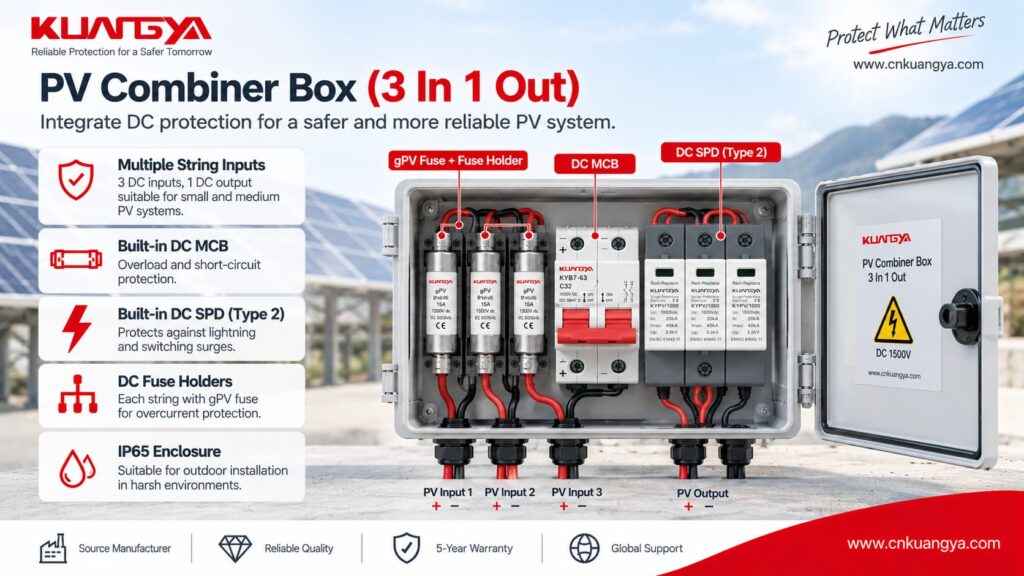
Photovoltaic DC systems require additional care.
A PV DC SPD must be suitable for:
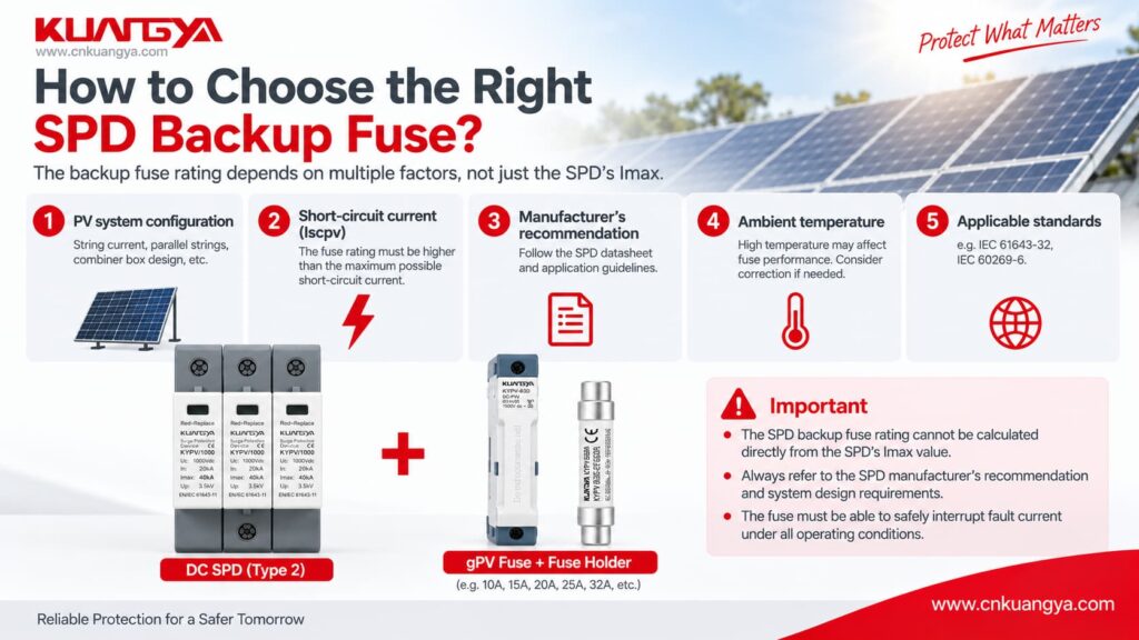
The exact Fusible de respaldo para SPD arrangement can depend on:
Before choosing backup protection, the SPD voltage itself must also be correct.
For more detail, see our DC SPD voltage selection guide for solar PV systems.
No.
A gPV fuse is specifically designed for photovoltaic applications, but this does no mean every PV SPD requires a separate gPV backup fuse.
The manufacturer’s instructions must be checked first.
Depending on the system design, existing PV overcurrent protection may already form part of the approved protection arrangement.
If a gPV fuse is required, it must also be suitable for:
For examples of PV-rated fuse links and holders, see KUANGYA’s DC gPV fuse range.
The product page is useful for understanding available PV fuse formats, but final SPD coordination must still follow the SPD manufacturer’s technical data.
Where dedicated backup protection is required, it is normally positioned in the SPD branch so that fault current flowing to the SPD can be interrupted.
A simplified concept is:
Busbar / Supply → F2 → SPD → required protection path
However, the exact wiring depends on:
Always follow the wiring diagram for the exact SPD.
Adding a fuse or breaker should not result in unnecessarily long SPD connections.
SPD connection conductors have inductance.
During a fast-rising surge current, additional lead length can increase the voltage appearing across the protected equipment.
This means backup protection should be coordinated while keeping the SPD connection path short and direct.
For PV systems, there is also another distance issue: the distance between the SPD location and the inverter.
These two distances should not be confused.
For a detailed explanation, see our guide to SPD distance from inverter and SPD connection lead length.
Sometimes.
The existing protective device may be acceptable if:
However, a dedicated SPD breaker can also provide practical advantages such as easier isolation and maintenance.
El punto importante es:
Dedicated protection does not automatically mean correctly coordinated protection.
The device must still match the SPD manufacturer’s requirements.
Because many power SPDs are connected in parallel, the main electrical load can continue operating even after the SPD branch is disconnected.
That means:
Power ON does not necessarily mean surge protection ON.
If the backup fuse opens, the cause should be investigated rather than simply replacing the fuse and re-energizing the system.
Las posibles causas son:
If you suspect the SPD itself has failed, see our guide on cómo saber si un SPD está defectuoso.
| Error | Why It Is Wrong |
|---|---|
| 40 kA SPD = 40 A fuse | Imax and fuse current rating describe completely different electrical quantities |
| Every Type 2 SPD needs 125 A | Backup protection is manufacturer-specific |
| Smaller fuse is always safer | It may disconnect unnecessarily during surge events |
| Internal SPD disconnector means no external protection is ever required | Internal and external protective functions are not necessarily identical |
| 125 A fuse = 125 A breaker | Fuse and breaker operating characteristics differ |
| F2 must always be installed | Existing F1 may already meet the SPD requirement |
| Ignore prospective short-circuit current | SPD protection must be coordinated with available fault current |
| Use AC examples for PV DC SPD | AC and PV DC systems have different requirements |
| Choose only by Imax | Imax does not determine backup-fuse rating |
| Use maximum permitted fuse automatically | “Maximum” is a limit, not necessarily the ideal rating |
Before selecting an fusible de respaldo o disyuntor del SPD, check the following:
| Consulte | Pregunta |
|---|---|
| Exact SPD | What manufacturer and model is installed? |
| Aplicación | AC or photovoltaic DC? |
| Tipo de SPD | Type 1, Type 1+2 or Type 2? |
| Tensión | Are Uc/Ucpv suitable for the system? |
| Upstream device | What is F1? |
| Manufacturer limit | What maximum backup protection is specified? |
| Dedicated F2 | Is it actually required? |
| Fault current | What is the prospective short-circuit current? |
| Fuse class | gG, gPV or another specified type? |
| Interruptor automático | What curve and breaking capacity are required? |
| Conductors | Is the conductor cross-section suitable? |
| Terminales | Can the SPD terminals accept the selected conductors? |
| Lead length | Are SPD connection leads short and direct? |
| Earthing | Is the protection path correctly connected? |
| Indication | Can failure or disconnection be detected? |
If several of these answers are unknown, selecting a backup fuse by guesswork is not appropriate.
IEC 61643-11 covers SPDs intended for connection to AC low-voltage power circuits and specifies performance and safety requirements, tests and ratings.
IEC 61643-31 applies specifically to SPDs intended for the DC side of photovoltaic installations up to 1.500 V CC.
IEC 60364-5-53 covers the selection and erection of electrical equipment for protection, isolation, switching, control and monitoring.
The current IEC consolidated version includes the 2019 base publication plus amendments from 2020 and 2024.
IEC 60364-5-53:2019+A1:2020+A2:2024
Applicable national standards, installation rules and manufacturer instructions must also be followed.
No.
A separate Fusible de respaldo para SPD is not always necessary.
If the existing upstream protective device already satisfies the manufacturer’s permitted backup-protection conditions, another fuse may not be required.
Some SPDs also include integrated backup protection.
There is no universal fuse size for an SPD.
Use the exact SPD datasheet and check:
Do not calculate the fuse size from Imax alone.
No.
125 A appears in several manufacturer examples, but it is not a universal Type 2 SPD value.
Published examples show SPDs with different arrangements, including:
Sometimes.
But the circuit breaker’s:
must be suitable.
Do not replace a specified fuse with a breaker simply because both devices have the same ampere rating.
No necesariamente.
A red status indicator commonly relates to the condition of the SPD’s internal protection module or disconnection mechanism.
An external backup fuse is a separate protective device.
Therefore, both the SPD status and the upstream or branch protection should be inspected.
Sí.
Because many power SPDs are connected in parallel, the protected load may remain energized even if the SPD has been disconnected.
This means surge protection can be lost while the equipment appears to operate normally.
No.
The requirement depends on:
Never assume every PV SPD needs the same gPV fuse.
Not directly.
Imax represents a surge-discharge current characteristic.
Fuse current rating relates to overcurrent protection.
A 40 kA Imax rating does not mean a 40 A backup fuse is required.
So, does an SPD need a backup fuse or circuit breaker?
Sometimes yes—but not always as a separate device.
Correcto SPD backup fuse selection starts with the manufacturer’s technical data rather than a universal ampere rating.
The correct decision depends on the relationship between:
SPD → F1 → F2 → available fault current → conductors → electrical system
Before installing additional backup protection, first check whether the existing upstream device already satisfies the SPD manufacturer’s requirements.
If dedicated protection is required, verify:
Most importantly:
Never select an SPD backup fuse only from Type 1 / Type 2, In or Imax. Use the exact manufacturer’s backup-protection requirements and the actual system conditions.
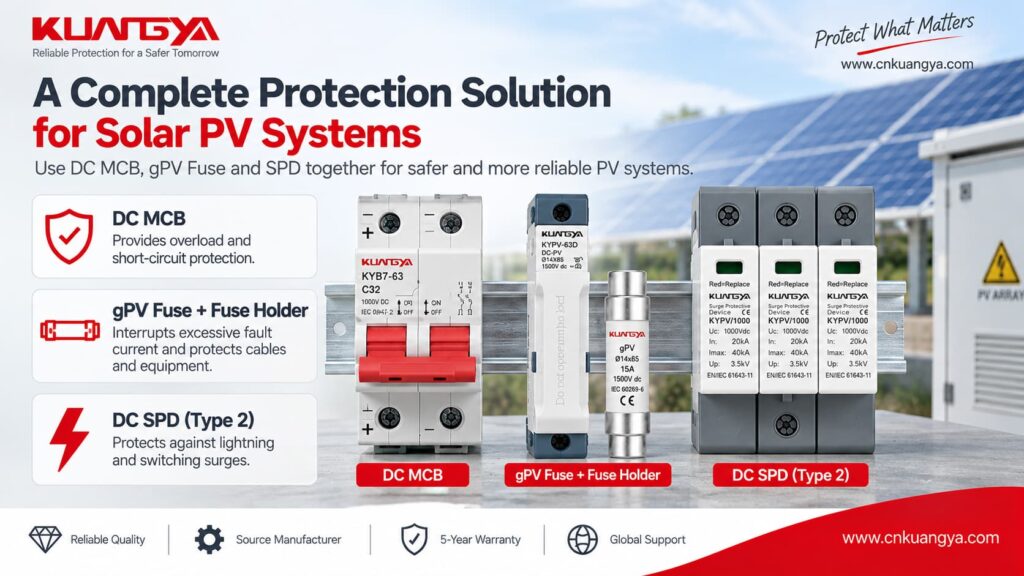
For photovoltaic applications, you can also review KUANGYA’s DC surge protective devices for solar PV systems when comparing Type 2 and Type 1+2 DC SPD options.

