温州市岳陽工業区 325000
勤務時間
月曜日~金曜日:午前7時~午後7時
週末午前10時~午後5時
温州市岳陽工業区 325000
勤務時間
月曜日~金曜日:午前7時~午後7時
週末午前10時~午後5時

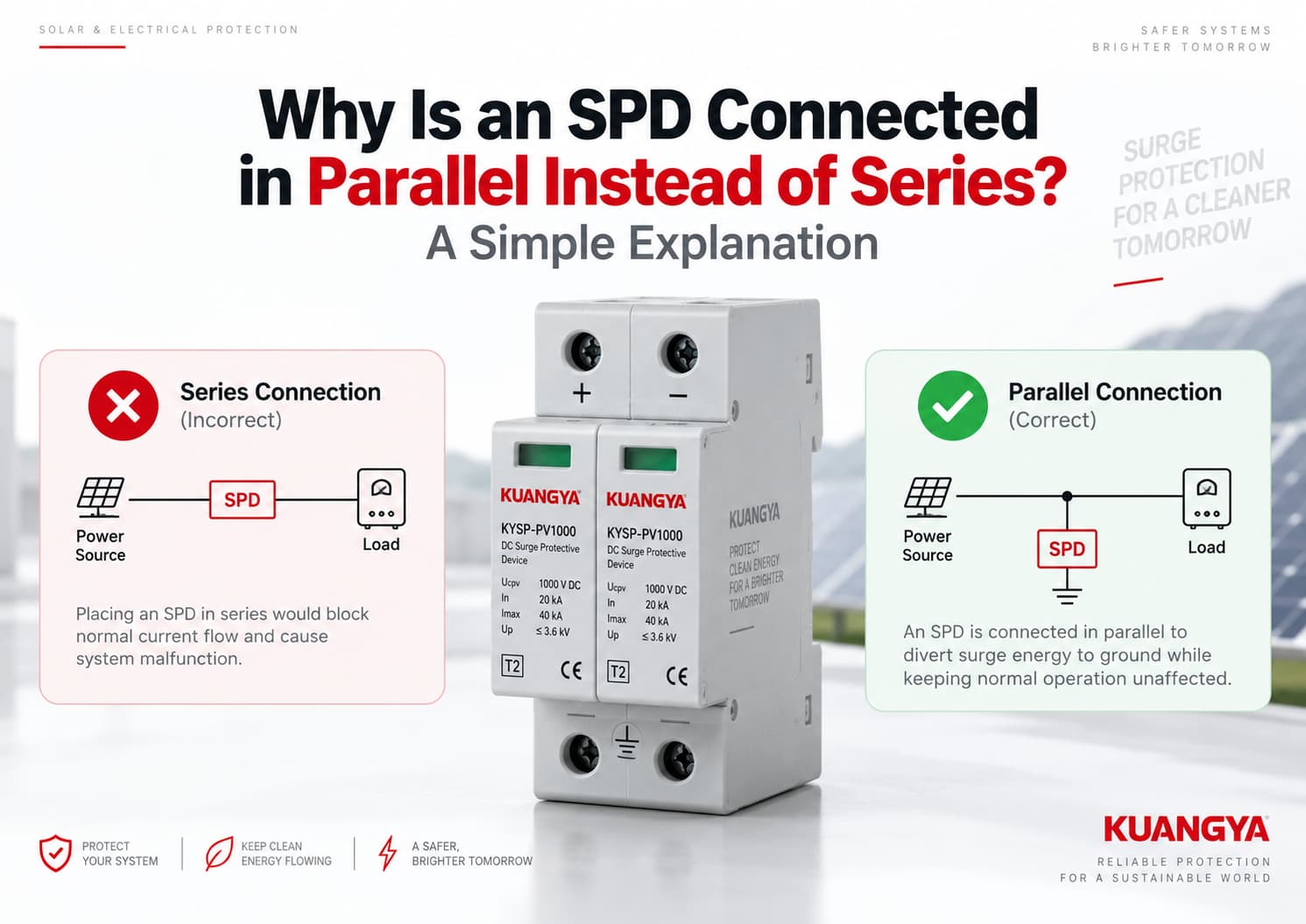
一般的なサージ防護デバイス(SPD)の設置状況を見ると、ヒューズや配線用遮断器(MCCB)とは異なる点があることに気づくかもしれません。.
ヒューズや配線用遮断器は通常、回路に対して直列に設置されるため、負荷電流はそれらを通ります。.
一般的な電源用SPDは通常、 並列に接続されます 保護対象の回路に対して。これが、多くの施工者がなぜ SPDが直列ではなく並列に接続されるのかと疑問に思う理由です。.
なぜですか?
簡潔に言えば、並列接続されたSPDは通常の負荷電流を流す必要がないためです。通常動作条件下では、SPDは高インピーダンス状態を維持します。過渡過電圧が発生すると、SPDは導通を開始し、サージ電流に対して低インピーダンスの経路を提供することで、保護対象機器に到達する電圧を制限します。.
これが、配電システムや太陽光発電システムにおいて、タイプ1およびタイプ2のSPDに並列接続が広く採用されている理由です。.
ただし、「SPD=常に並列」というわけではありません。特定の用途向けには、直列接続型のSPDやサージフィルタも存在します。本記事では、主に交流配電システムや太陽光発電DCシステムで使用される一般的な並列接続型電源用SPDについて解説します。.
典型的な例 並列接続されたSPD 負荷の通常動作電流を流すことなく、過渡過電圧イベントに応答するように設計されています。.
通常の状態では
電源 → 負荷
SPDは待機状態を維持します。.
サージが発生すると、SPDはその電気的特性を変化させ、保護経路を通じてサージ電流を逃がすことで、敏感な機器に印加される電圧を制限します。.
簡略化した並列接続の構成は以下の通りです。
電源 ───────────── 負荷
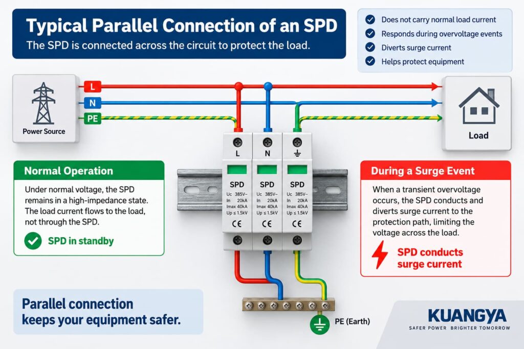
SPDは通常の負荷電流経路に直接挿入されるのではなく、回路に対して並列に接続されます。. フエニックス・コンタクトのサージ保護の基礎 また、SPDは保護対象機器と並列に、あるいは関連する導体間に設置できると説明しています。.
イートン社も同様に、並列接続(またはシャント接続)型SPDについて、接続導体には通常の供給電流は流れず、過渡現象に伴う短時間の電流のみが流れると説明しています。.
その基本的な違いが、一般的な電源用SPDのほとんどが並列に設置される理由を説明しています。.
並列接続を理解するには、まずサージが発生していない時にSPDがどのような状態にあるかを理解することが役立ちます。.
通常動作中、システム電圧はSPDが有意に導通するレベルを下回ったままです。.
MOVベースのSPDの場合、保護素子は通常電圧条件下で比較的高いインピーダンスを示します。.
これは、主動作電流が通常の電源回路を通って負荷へと流れ続けることを意味します。.
SPDは本質的に待機状態にあります。.
簡略化した図は以下の通りです。
電源 ───────────────── 負荷
これは、すべてのSPDに電流が全く流れないことを意味するわけではありません。SPDの技術や設計によっては、わずかな漏れ電流や動作電流が存在する場合があります。.
重要な点は以下の通りです。
通常の負荷電流は、一般的な並列接続されたSPDを流れる必要はありません。.
SPDは、機器の動作電流を継続的に流さなければならないコンポーネントではなく、主回路の傍らで待機している保護経路であると考えてください。.
サージとは、落雷に関連する過渡現象や開閉操作などの事象によって引き起こされる、短時間の電圧上昇のことです。.
SPDの両端の電圧が十分に上昇すると、SPDの保護素子が導通を開始します。.
保護素子が過渡過電圧にどのように応答するかについての詳細な説明は、当社のガイドを参照してください。 DC SPDの仕組み.
そのインピーダンスは、通常の状態と比較して急激に低下します。.
これにより、サージ電流が利用可能な保護経路を通って流れ、保護対象機器に発生する過渡電圧を制限します。.
簡略化した図は以下の通りです。
機器
ただし、この図はあくまで簡略化された例です。.
SPDは すべてのサージを直接接地へ逃がせるとは限らない.
電気システムおよびSPDの設計に応じて、以下の保護モードが存在する場合がある:
このため、次のように表現する方がより正確です:
SPDはサージ電流に対して制御された経路を提供し、保護対象機器にかかる過渡電圧を制限します。.
正確な電流経路は、SPDの構成およびシステムトポロジーに依存します。.
SPDが並列に接続される理由を理解するには、通常動作時とサージ発生時の両方で何が起こるかを確認することが役立ちます。.
いくつかの重要な理由により、 並列接続されたSPD は配電システムで広く使用されています。.
これは、SPDと回路遮断器やヒューズなどのデバイスとの間の最も大きな違いの一つです。.
インバータが通常数十アンペアで動作していると想像してください。.
一般的な並列接続型SPDの場合、その動作電流がSPDを継続的に通過する必要はありません。.
その代わりだ:
電源 ───────────────── 負荷
SPDは保護対象の回路に対して並列に接続されます。.
つまり、SPDは下流のすべての負荷の全動作電流に基づいて選定するのではなく、主にサージ保護要件に基づいて選定できることを意味します。.
フエニックス・コンタクト社も同様に、同社の並列設置型電源用SPDは、回路の定格電流を流すのではなく、配電システムに対して並列に接続された分岐として電気的に機能すると述べています。.
一般的なSPDは電圧感応型です。.
通常のシステム電圧下では、SPDはほとんど動作しません。.
過渡電圧が通常の動作範囲を超えて上昇すると、保護素子が導通を開始します。.
これは、ヒューズ、配線用遮断器、または断路器とは根本的に異なります。.
例えば、こうだ:
ヒューズ
電源 → ヒューズ → 負荷
配線用遮断器
電源 → 遮断器 → 負荷
一般的な並列接続型SPD
電源 ────────── 負荷
ヒューズや遮断器は物理的に負荷経路に配置されているため、通常は回路電流を流す必要があります。.
並列接続型SPDはそうではありません。.
SPDの目的は、負荷に到達するすべてのサージを「遮断」することではありません。.
その代わり、電圧制限型SPDは上昇する過渡電圧に応答し、サージ電流を導通させます。.
この動作により、保護対象回路にかかる電圧が制限されます。.
例えば、簡略化したPVシステムでは以下のようになります。
PVアレイ ───────────────── インバータ
通常運転時、PV電力はインバータに向かって流れ続けます。.
サージ発生時、SPDは保護モードに従って導通し、過渡電圧を本来到達するはずのレベルよりも低く抑える役割を果たします。.
これが、SPDを回路に対して並列に配置する基本的な理由です。.
一般的なSPDは並列分岐として接続されるため、電源と負荷の間の通常の導通経路にはなりません。.
これには実用上の重要な利点があります。.
システムの通常動作電流は、SPDの保護素子を継続的に通過することに依存しません。.
もちろん、これは設置後にSPDを放置してよいという意味ではありません。.
SPDは異常な電気的ストレスを受けた後に劣化または切断される可能性があるため、その状態表示は定期的に確認する必要があります。.
SPDが並列に接続される理由を理解することは、一般的な分路接続型SPDが通常の負荷経路に対して直列に配置されない理由を説明する助けにもなる。.
配線用遮断器やヒューズは、回路電流を流す必要があるため、通常は直列に設置されます。一般的な並列接続型SPDは、それとは異なる機能のために設計されています。.
真の直列接続は以下のようになります:
電源 → デバイス → 負荷
SPDアセンブリ全体を負荷経路に挿入する場合、SPDは連続的な負荷電流に対応する必要があります。.
その導体、端子、熱設計、短絡性能、および故障時の挙動はすべて、その用途に合わせて設計される必要があります。.
一般的なDINレール取り付け型のタイプ1またはタイプ2の並列接続型SPDは、通常そのような使用方法ではありません。.
これはSPDの銘板を読み解く上で特に重要なポイントです。.
例えば、あるSPDに以下のように記載されているとします:
In = 20 kA
そして
Imax = 40 kA
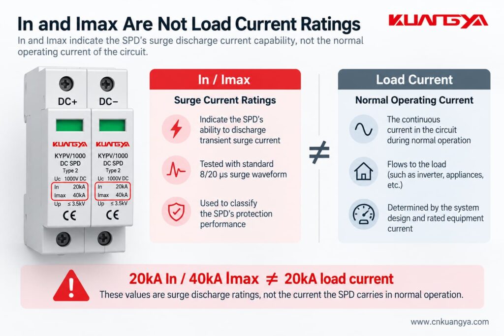
これらのSPD定格についてまだ不明な点がある場合は、当社の DC SPD仕様ガイドをご参照ください Ucpv、In、Imax、UpおよびIscpvについて詳細に説明します。.
これらの数値は、 ない SPDが20 kAまたは40 kAの通常負荷電流を継続的に流すように設計されていることを意味するものではありません。.
タイプ2 SPDにおいて、, で は8/20 μsの電流インパルスに関連する公称放電電流を指し、一方で アイマックス は8/20 μsのインパルスに関連する最大放電電流を指します。.
フエニックス・コンタクトの技術定義においても、InおよびImaxはSPDを流れるインパルス電流値として説明されており、通常の連続負荷電流定格ではありません。.
したがって:
InおよびImaxはサージ放電電流の定格値であり、負荷の通常動作電流ではありません。.
この区別は、SPDを選定または説明する際に非常に重要です。.
そうだ。.
これは重要な例外です。.
本記事で取り上げた一般的なタイプ1およびタイプ2の電源用SPDは通常並列に設置されますが、直列接続型のSPDアセンブリや直列接続型のサージフィルタも存在します。.
シュナイダーエレクトリックは、直列接続製品は特定の負荷の近くにインラインで設置されるのが一般的である一方、並列接続SPDは配電盤や分電盤においてより一般的な構成であると指摘しています。.
直列接続製品は、回路の負荷電流を流せるように特別に設計される必要があります。.
したがって、以下のように言うのは誤りです:
“SPDを直列に接続することは決してできません。”
より技術的に正確な記述は以下の通りです。
一般的な配電用タイプ1およびタイプ2のSPDは並列接続されますが、特定の用途向けに設計された直列接続型のサージ保護製品も存在します。.
太陽光発電(PV)および一般的な配電盤の用途では、必ず実際のSPDメーカーの配線図に従ってください。.
下表は、一般的な 並列接続されたSPD が、通常の負荷電流経路に直接設置されるデバイスとどのように異なるかを示しています。.
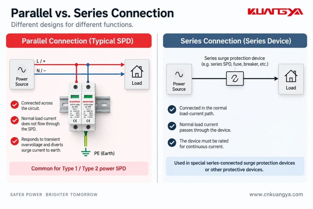
| 特徴 | 一般的な並列接続型SPD | 直列接続型デバイス |
|---|---|---|
| 通常の負荷経路に直接接続 | いいえ | はい |
| 通常の負荷電流がデバイス全体を通過する | いいえ | はい |
| Type 1 / Type 2 電源用SPDにおける一般的な構成 | はい | あまり一般的ではない |
| 主な目的 | サージ電流経路を提供することで過渡過電圧を制限する | 製品設計に依存する |
| デバイス全体にとって重要な定格連続電流 | 通常、インラインデバイスとは異なる方法 | はい |
| 設置リード線の長さは保護性能に影響を与える | はい | 内部配置により、外部並列リード線の長さによる影響を低減できる場合がある |
| 代表的な用途 | 配電盤、機器入口、太陽光発電システム | 特定の感度の高い負荷、または特殊な保護・フィルタリング用途 |
重要な点は、どちらか一方の方法が普遍的に「優れて」おり、もう一方が「劣って」いるということではない“
それらは異なる製品アーキテクチャである.
ただし、一般的なDINレール取り付け型電源用SPDの場合、並列接続が通常想定される設置方法である.
同様の原則は多くの太陽光発電システムにも適用され、SPDはメーカーの配線構成に従ってDC回路と並列に接続されます。.
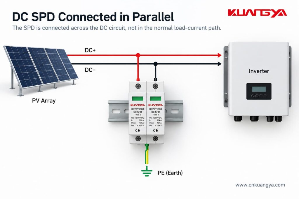
ただし、DC SPDの配線には細心の注意が必要です。.
すべてのPV用SPDが単純に以下のように配線されていると想定するのは誤りです。
DC+ → SPD → PE
実際の内部保護回路は異なる場合があります。.
製品およびPVシステムの構成に応じて、SPDは以下の間での保護モードを提供する場合があります。
接地システムやPVアーキテクチャの違いにより、異なるSPD回路構成が使用されます。.
並列接続されるPV用SPDの場合、正確な端子配置はSPDの設計、システムトポロジー、およびメーカーの配線図に依存します。.
そのため、SPD本体に印刷されている、またはメーカーの設置説明書に記載されている配線図が非常に重要となります。.
太陽光発電DCアプリケーションについては、専用のIEC製品規格としてIEC 61643-31が定められています。DEHN社は、PVおよび低圧SPDアプリケーションに関連する設置規格として、IEC 60364-7-712およびIEC 60364-5-53も挙げています。.
AC用SPDとDC用SPDは同様のサージ保護原理に基づいているものの、両システムに互換性はありません。.
直流には自然なゼロクロス点が存在しないため、DCアークの遮断がより困難であり、DCシステムには特有の課題があります。.
このため、SPDはDC電圧、システム構成、および用途に適合した専用のものを選定する必要があります。.
常に以下の項目を確認してください:
設置前。.
KUANGYA製KYPV/1000タイプ2 DC SPDを例に挙げると、銘板には以下のようなパラメータが記載されています。
これらの値は、SPDの電気的性能の各項目を示しています。.
Ucは、SPDに規定された最大連続使用電圧です。.
適切な定格電圧を選択する際には、システム電圧および想定される動作条件を考慮しなければならない。.
Inは公称放電電流である。.
タイプ2 SPDの場合、これは8/20 μsのインパルス電流波形に関連付けられる。.
ImaxはSPDに対して規定された最大放電電流であり、このタイプのデバイスにおいても8/20 μsの波形に関連付けられる。.
ImaxはIn以上である。.
Upは電圧防護レベルである。.
これは、規定された試験条件下におけるSPDの電圧制限性能を示すものである。.
本日のトピックの要点は以下の通りである。
20 kAのInおよび40 kAのImaxは、通常動作時にSPDに20 kAまたは40 kAの電流が継続的に流れることを意味するものではありません。.
これらは過渡サージ電流のパラメータです。.
That is another reason why comparing an SPD’s In or Imax directly with the load current of an inverter is incorrect.
そうだ。.
In fact, connection length is extremely important for a parallel-connected SPD.
A surge has a very fast current rise.
The connecting conductors therefore have inductance, and the rapidly changing surge current can create an additional voltage drop along those conductors.
That additional voltage is effectively added to the voltage experienced by the protected equipment.
IEA PVPSの NEMA’s guidance on hard-wired SPD installation, the size and length of the connecting leads can affect the performance of a parallel-connected SPD, and short, direct connections are preferred.
Phoenix Contact makes the same point: long connecting conductors can increase the effective voltage protection level seen in the installation.
So even if two installations use exactly the same SPD, their real-world protection performance may not be identical if one has much longer connection conductors.
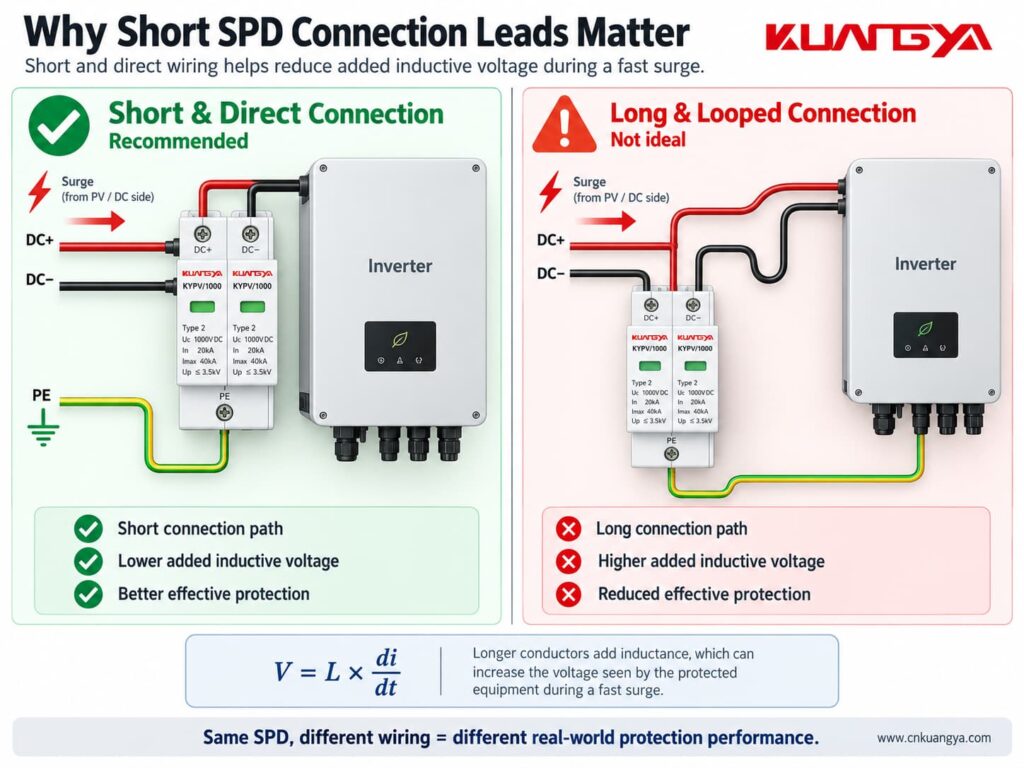
The SPD connection should generally be:
This is also why SPD location matters.
If you want to understand this issue in more detail, see our guide:
The exact position depends on the system being protected.
For example, an SPD may be installed:
If your inverter already includes surge protection, do not assume that an additional external SPD is automatically unnecessary. See 太陽光発電用インバータにDC SPDが内蔵されている場合、外部SPDは必要か?
The objective is not simply to put “one SPD somewhere in the system.”
The SPD should be positioned as part of a coordinated protection concept.
For PV systems in particular, cable length and the location of the inverter, modules and building entry points can affect whether additional SPDs are appropriate.
IEA PVPSの DEHN’s photovoltaic surge protection guidance, SPDs should be installed as close as possible to the equipment being protected, such as the inverter, on both the AC and DC sides.
The specific requirements should always be determined from the applicable installation standard, risk assessment and manufacturer instructions.
Sometimes yes, but not always in exactly the same way.
This is another area where oversimplified advice can cause problems.
A parallel SPD may require an external:
depending on the SPD design and installation.
Other SPDs may include internal protective or disconnecting components.
The correct arrangement depends on factors such as:
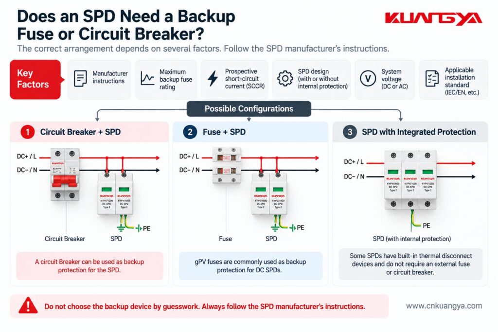
NEMA specifically advises installers to follow the manufacturer’s requirements regarding fuses, breakers and connection leads.
Therefore, do not assume:
“Every SPD needs exactly the same backup breaker.”
And do not assume:
“Because the SPD is connected in parallel, no overcurrent protection is ever required.”
どちらの記述も誤りである可能性がある。.
Always check the SPD datasheet and installation instructions.
Imagine two identical SPDs.
The SPD is mounted very close to the protected equipment, with short and direct conductors.
The SPD is several meters away and connected through long conductors.
Although the SPD nameplate is identical, the effective protection at the equipment can be different.
This happens because the connecting conductors contribute additional inductive voltage during a fast surge.
NEMA explains this relationship using:
V = L × di/dt
where:
The faster the current changes and the more inductance there is in the connection, the greater the additional voltage can become.
You do not need to calculate this formula for every normal installation.
実践的な教訓はもっと単純です:
Keep SPD connections short and direct.
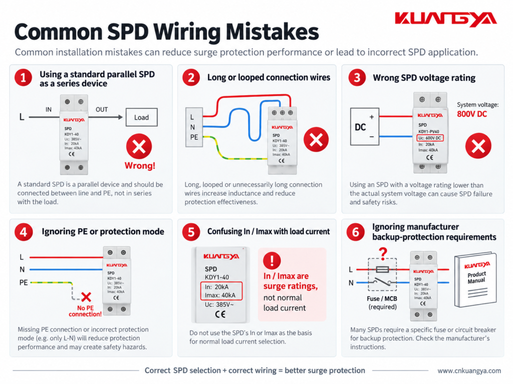
Understanding why the SPD is connected in parallel also makes several common installation mistakes easier to recognize.
Do not simply place a normal parallel DIN-rail SPD in the main load path unless the manufacturer’s design specifically requires that configuration.
Follow the wiring diagram for the exact product.
A good SPD with poor wiring may provide worse protection than expected.
Long leads increase inductive voltage during a surge.
Short and direct routing is generally preferred.
Do not assume every surge simply flows from one line terminal to earth.
The protection modes depend on the electrical network and SPD design.
Correct PE, bonding and circuit connections are essential where required by the product and installation design.
An SPD must be suitable for the voltage that can continuously appear at its terminals.
This is particularly important in PV systems, where string open-circuit voltage changes with temperature.
Choosing an SPD only because it says “DC SPD” is not enough.
The voltage rating must match the actual PV system design.
For a step-by-step method, see our DC SPD voltage selection guide for solar PV systems.
This is one of the most common misunderstandings.
An SPD marked:
In = 20 kA
does not mean:
Normal load current = 20 kA
In and Imax describe surge-current performance under specified impulse conditions.
They are not normal operating-current ratings.
Do not guess the fuse or breaker size.
Different SPD designs can have different backup protection requirements.
Some products also include integrated protective components.
Check the actual product documentation.
Many modular SPDs include a visual status indicator.
If the indicator shows a fault or replacement condition, the protection module may need to be replaced.
Some SPDs also have remote signaling contacts for connection to alarms, PLCs or monitoring systems.
Installing the SPD is only the first step.
Its condition should also be checked during maintenance.
For common warning signs and replacement indicators, see How to Know If an SPD Is Bad?
A circuit breaker and an SPD protect against different electrical problems.
A circuit breaker is mainly intended to interrupt abnormal current conditions such as overloads or short circuits.
Because it must sense and interrupt circuit current, it is connected in series with the load.
An SPD is intended to limit transient overvoltage.
A typical power SPD is connected in parallel so that it can conduct surge current when the transient voltage rises.
That means:
Circuit breaker → current protection
SPD → transient overvoltage protection
One cannot normally replace the other.
They perform different jobs.
The same principle applies to a fuse.
A fuse is installed in series with the circuit it protects.
Normal load current passes through the fuse element.
If excessive current persists, the fuse element opens the circuit.
A typical SPD behaves differently.
It remains connected across the protected circuit and responds mainly when the voltage reaches a level that causes its protective elements to conduct.
So although fuses, breakers and SPDs may all appear in the same electrical panel, their functions and connection methods are not the same.
Most common Type 1 and Type 2 power SPDs used in distribution boards and similar applications are connected in parallel with the circuit they protect.
However, specially designed series-connected SPDs and surge filters also exist.
Always follow the wiring instructions for the exact product.
A typical SPD is connected in parallel because it does not need to carry the normal load current.
During normal voltage conditions, it remains in a high-impedance state.
When a transient overvoltage occurs, it conducts surge current through its protection path and limits the voltage across the protected equipment.
The normal load current does not normally flow through a typical parallel-connected SPD.
However, a small leakage or operating current may exist depending on the SPD technology and design.
Therefore, saying “absolutely no current flows through an SPD” would not be technically precise.
必ずしもそうではない。.
An SPD may operate between line and neutral, line and earth, neutral and earth, line and line, or different DC conductors depending on its protection modes.
The exact surge-current path depends on the SPD and electrical system configuration.
Many power SPDs are designed to be connected in parallel across the appropriate conductors of the supply.
However, the exact wiring arrangement depends on the SPD type, system earthing arrangement, required overcurrent protection and manufacturer instructions.
Never determine the connection from a generic diagram alone.
A normal parallel SPD is not designed to serve as the continuous main load-current path.
Installing an inline device requires a product specifically designed for that purpose, including suitable current, terminal, fault and thermal ratings.
そうだ。.
In and Imax are surge-discharge current parameters.
They should not be confused with PV string operating current, short-circuit current or inverter input current.
The general surge-protection principle is similar, but DC and AC systems have important differences.
The voltage rating, polarity, protection modes, earthing arrangement and internal SPD design may differ.
For PV systems, always use an SPD intended for the specific DC application and follow its wiring diagram.
It depends on the protection mode and system design.
Many power SPDs include protection paths involving PE, but not every surge protection mode is simply conductor-to-earth.
Use the manufacturer’s circuit diagram and the applicable earthing and bonding requirements.
そうだ。.
Long SPD connection conductors add inductance and can increase the voltage experienced by the protected equipment during a fast transient.
For this reason, connection conductors should generally be kept as short and direct as practical.
If you only remember a few things from this article, remember these:
So, why is an SPD connected in parallel instead of series?
For a typical Type 1 or Type 2 並列接続されたSPD, the normal load current does not pass through the SPD as it would through a series-connected device.
Under normal operating conditions, the SPD remains largely in standby.
When a surge occurs, it conducts through its designed protection path and helps limit the voltage appearing across the protected equipment.
That is fundamentally different from a fuse or circuit breaker, which normally carries the circuit current and is therefore installed in series.
However, correct SPD installation involves more than simply choosing “parallel.”
The SPD voltage rating, protection modes, location, conductor length, earthing and bonding arrangement, backup protection and manufacturer wiring diagram all affect the final protection performance.
For solar PV systems in particular, always use an SPD designed for the relevant DC application and verify the actual system voltage and wiring configuration before installation.

