Zona industriale di WengYang Yueqing Wenzhou 325000
Orario di lavoro
Da lunedì a venerdì: dalle 7.00 alle 19.00
Fine settimana: 10.00 - 17.00
Zona industriale di WengYang Yueqing Wenzhou 325000
Orario di lavoro
Da lunedì a venerdì: dalle 7.00 alle 19.00
Fine settimana: 10.00 - 17.00

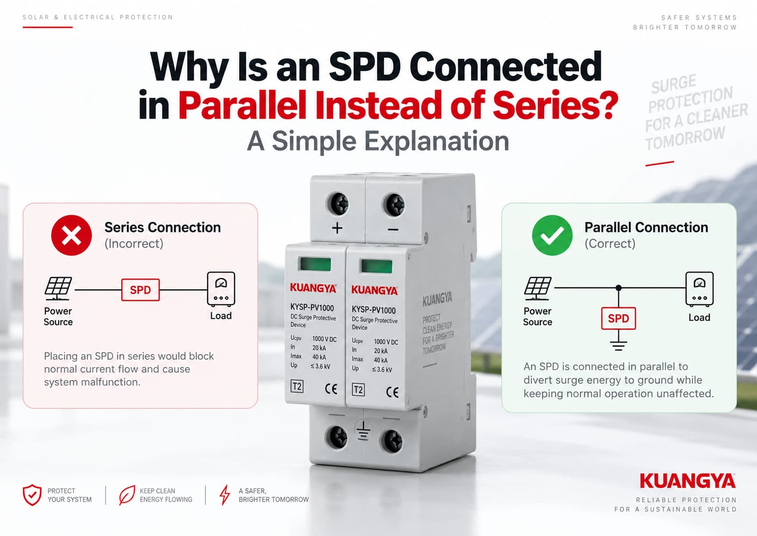
Se si osserva una tipica installazione di un dispositivo di protezione contro le sovratensioni (SPD), si potrebbe notare una differenza rispetto a un fusibile o a un interruttore magnetotermico.
Un fusibile o un interruttore magnetotermico è normalmente installato in serie al circuito, in modo che la corrente di carico lo attraversi.
Un tipico SPD di potenza è solitamente collegato in parallelo al circuito che protegge, motivo per cui molti installatori si chiedono perché un SPD sia collegato in parallelo anziché in serie.
Perché?
La risposta semplice è che un SPD collegato in parallelo non deve trasportare la normale corrente di carico. In condizioni operative normali, rimane in uno stato ad alta impedenza. Quando si verifica una sovratensione transitoria, l'SPD inizia a condurre e fornisce un percorso a bassa impedenza per la corrente di sovratensione, limitando la tensione che raggiunge l'apparecchiatura protetta.
Ecco perché il collegamento in parallelo è ampiamente utilizzato per gli SPD di Tipo 1 e Tipo 2 nei sistemi di distribuzione elettrica e fotovoltaici.
Tuttavia, “SPD = sempre in parallelo” non è una regola assoluta. Esistono anche SPD collegati in serie e filtri di sovratensione per determinate applicazioni. In questo articolo, ci occupiamo principalmente del comune SPD di potenza collegato in parallelo utilizzato nei sistemi di distribuzione CA e nei sistemi solari fotovoltaici CC.
Un tipico SPD collegato in parallelo è progettato per rispondere a eventi di sovratensione temporanea senza trasportare la normale corrente operativa del carico.
In condizioni normali:
Fonte di alimentazione → Carico
L'SPD rimane in standby.
Quando si verifica una sovratensione, l'SPD modifica il proprio comportamento elettrico e conduce la corrente di sovratensione attraverso il suo percorso di protezione, contribuendo a limitare la tensione che si manifesta sulle apparecchiature sensibili.
Una disposizione in parallelo semplificata appare come segue:
Fonte di alimentazione ───────────── Carico
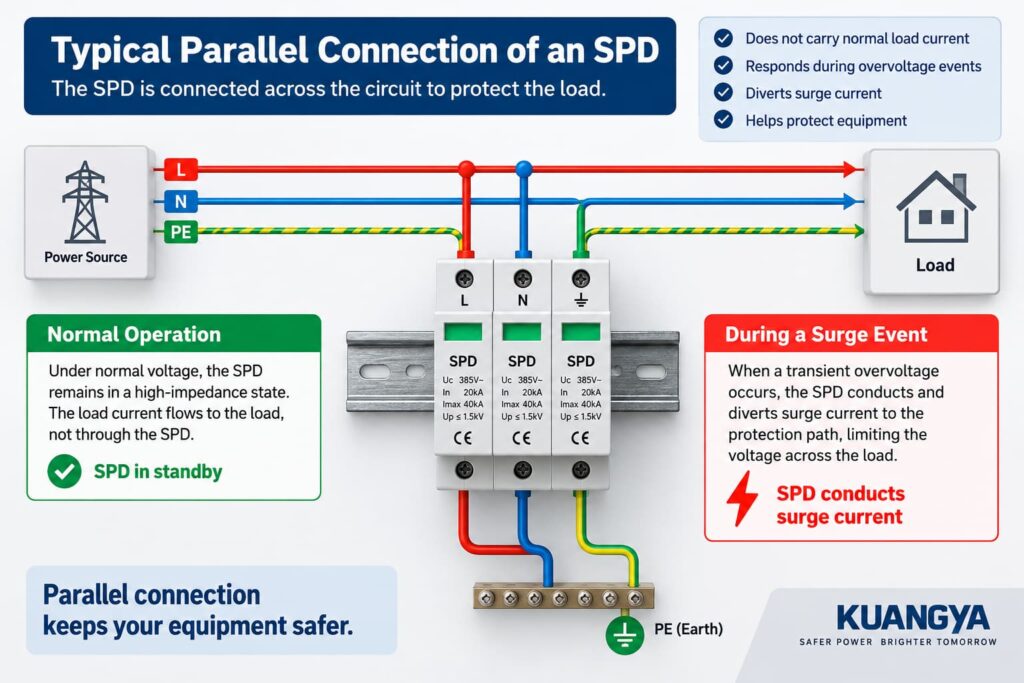
L'SPD è collegato attraverso il circuito anziché inserito direttamente nel percorso della corrente di carico normale. Fondamenti della protezione contro le sovratensioni di Phoenix Contact spiega inoltre che gli SPD possono essere installati in parallelo con l'apparecchiatura protetta o tra i conduttori pertinenti.
Eaton descrive gli SPD collegati in parallelo, o in derivazione, allo stesso modo: i loro conduttori di collegamento non trasportano la normale corrente di alimentazione, ma trasportano invece la corrente di breve durata associata agli eventi transitori.
Questa differenza fondamentale spiega perché la maggior parte degli SPD di potenza comuni viene installata in parallelo.
Per comprendere il collegamento in parallelo, è utile innanzitutto capire cosa fa l'SPD in assenza di sovratensioni.
Durante il normale funzionamento, la tensione di sistema rimane al di sotto del livello in cui l'SPD conduce in modo significativo.
Per un SPD basato su MOV, l'elemento di protezione presenta un'impedenza relativamente elevata in condizioni di tensione normale.
Ciò significa che la corrente operativa principale continua a fluire attraverso il normale circuito di alimentazione verso il carico.
L'SPD è essenzialmente in standby.
Una visione semplificata è:
Alimentazione ───────────────── Carico
Ciò non significa necessariamente che attraverso ogni SPD non scorra assolutamente alcuna corrente. A seconda della tecnologia e del design dell'SPD, può essere presente una piccola corrente di dispersione o di funzionamento.
Il punto importante è:
La normale corrente di carico non deve necessariamente fluire attraverso un tipico SPD collegato in parallelo.
Si pensi all'SPD come a un percorso di protezione in attesa a fianco del circuito principale, piuttosto che come a un componente che deve trasportare continuamente la corrente operativa dell'apparecchiatura.
Una sovratensione è un aumento di tensione di breve durata che può essere causato da eventi come transitori legati ai fulmini o operazioni di commutazione.
Quando la tensione ai capi dell'SPD aumenta a sufficienza, gli elementi di protezione dell'SPD iniziano a condurre.
Se desideri una spiegazione più approfondita su come gli elementi di protezione reagiscono alle sovratensioni transitorie, consulta la nostra guida su come funziona un SPD DC.
La sua impedenza diminuisce drasticamente rispetto alla condizione normale.
Ciò consente alla corrente di sovratensione di fluire attraverso il percorso di protezione disponibile e limita la tensione transitoria che si manifesta ai capi dell'apparecchiatura protetta.
Una rappresentazione semplificata è:
Apparecchiatura
Tuttavia, questo diagramma è solo un esempio semplificato.
Un SPD fa non deviano sempre ogni sovratensione direttamente a terra.
A seconda dell'impianto elettrico e del design dell'SPD, possono esistere modalità di protezione tra:
Per questo motivo, è più preciso affermare:
L'SPD fornisce un percorso controllato per la corrente di sovratensione e limita la tensione transitoria attraverso l'apparecchiatura che protegge.
L'esatto percorso della corrente dipende dalla configurazione dell'SPD e dalla topologia del sistema.
Per capire perché un SPD viene collegato in parallelo, è utile osservare cosa accade sia durante il normale funzionamento che durante un evento di sovratensione.
Ci sono diverse ragioni importanti per cui un SPD collegato in parallelo è ampiamente utilizzato nei sistemi di distribuzione dell'energia.
Questa è una delle maggiori differenze tra un SPD e dispositivi come un interruttore automatico o un fusibile.
Immagina che un inverter operi normalmente a decine di ampere.
Con un tipico SPD collegato in parallelo, tale corrente operativa non deve passare continuamente attraverso l'SPD.
Invece:
Sorgente ───────────────── Carico
L'SPD è collegato in parallelo al circuito protetto.
Ciò significa che l'SPD può essere selezionato principalmente in base ai requisiti di protezione dalle sovratensioni piuttosto che in base alla corrente operativa totale di ogni carico a valle.
Phoenix Contact osserva analogamente che i suoi SPD di potenza installati in parallelo appaiono elettricamente come una derivazione collegata al sistema di distribuzione dell'energia, anziché trasportare la normale portata di corrente del circuito.
Un tipico SPD è sensibile alla tensione.
Durante la normale tensione di sistema, rimane sostanzialmente inattivo.
Quando una tensione transitoria supera il normale campo operativo, gli elementi di protezione iniziano a condurre.
Questo è fondamentalmente diverso da un fusibile, un interruttore automatico o un sezionatore.
Ad esempio:
Fusibile
Sorgente → Fusibile → Carico
Interruttore automatico
Sorgente → Interruttore → Carico
Tipico SPD in parallelo
Sorgente ────────── Carico
Un fusibile o un interruttore automatico deve normalmente trasportare la corrente del circuito poiché si trova fisicamente nel percorso del carico.
Un SPD in parallelo non lo fa.
Lo scopo di un SPD non è quello di “bloccare” ogni sovratensione prima che raggiunga il carico.
Invece, un SPD limitatore di tensione risponde all'aumento della tensione transitoria e conduce la corrente di sovratensione.
Questa azione limita la tensione attraverso il circuito protetto.
Ad esempio, in un sistema fotovoltaico semplificato:
Campo FV ───────────────── Inverter
Durante il normale funzionamento, l'energia fotovoltaica continua a fluire verso l'inverter.
Durante un evento di sovratensione, l'SPD conduce in base alla sua modalità di protezione e contribuisce a mantenere la tensione transitoria a un livello inferiore rispetto a quello che raggiungerebbe altrimenti.
Questo è il motivo fondamentale per cui l'SPD viene posizionato in parallelo al circuito.
Poiché il tipico SPD è collegato come una derivazione in parallelo, non diventa il normale percorso conduttivo tra la sorgente e il carico.
Ciò comporta un importante vantaggio pratico.
La corrente operativa normale del sistema non dipende dal passaggio continuo attraverso gli elementi di protezione dell'SPD.
Naturalmente, ciò non significa che un SPD possa essere ignorato dopo l'installazione.
Gli SPD possono degradarsi o scollegarsi in seguito a sollecitazioni elettriche anomale, pertanto il loro stato di funzionamento deve essere controllato periodicamente.
Comprendere perché un SPD è collegato in parallelo aiuta anche a spiegare perché un tipico SPD collegato in derivazione non viene posizionato in serie al normale percorso del carico.
Gli interruttori automatici e i fusibili sono normalmente installati in serie perché devono trasportare la corrente del circuito. Un tipico SPD in parallelo è progettato per una funzione diversa.
Un vero collegamento in serie si presenta così:
Sorgente → Dispositivo → Carico
Se l'intero gruppo SPD venisse inserito nel percorso del carico, l'SPD dovrebbe essere in grado di gestire la corrente di carico continua.
I suoi conduttori, i terminali, il design termico, le prestazioni in caso di cortocircuito e il comportamento in caso di guasto dovrebbero essere tutti progettati per tale applicazione.
Non è così che viene normalmente utilizzato il comune SPD in parallelo di Tipo 1 o Tipo 2 su guida DIN.
Questo è un punto particolarmente importante quando si legge la targhetta di un SPD.
Supponiamo che un SPD sia contrassegnato come segue:
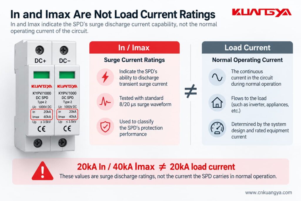
In = 20 kA
e
Imax = 40 kA
Se queste specifiche degli SPD risultano ancora poco chiare, la nostra guida alle specifiche degli SPD in corrente continua spiega più dettagliatamente Ucpv, In, Imax, Up e Iscpv.
Questi numeri non non significano che l'SPD è progettato per trasportare continuamente 20 kA o 40 kA di corrente di carico normale.
Per gli SPD di Tipo 2, In si riferisce alla corrente nominale di scarica associata a un impulso di corrente 8/20 μs, mentre Imax si riferisce alla corrente massima di scarica associata a un impulso 8/20 μs.
Le definizioni tecniche di Phoenix Contact descrivono analogamente In e Imax come valori di corrente impulsiva che attraversano l'SPD, non come valori nominali di corrente di carico continuo normale.
Quindi:
In e Imax sono valori nominali di corrente di scarica da sovratensione. Non rappresentano la normale corrente operativa del carico.
Questa distinzione è molto importante quando si seleziona o si spiega un SPD.
No.
Questa è un'eccezione importante.
Sebbene i comuni SPD di alimentazione di Tipo 1 e Tipo 2 discussi in questo articolo siano generalmente installati in parallelo, esistono anche gruppi SPD collegati in serie e filtri di sovratensione collegati in serie.
Schneider Electric osserva che i prodotti collegati in serie vengono solitamente installati in linea vicino a carichi specifici, mentre gli SPD collegati in parallelo rappresentano la configurazione più comune nei quadri elettrici e nei pannelli di distribuzione.
Un prodotto collegato in serie deve essere progettato specificamente per trasportare la corrente di carico del circuito.
Pertanto, sarebbe errato affermare:
“Un SPD non può mai essere collegato in serie.”
Un'affermazione tecnicamente più accurata è:
La maggior parte degli SPD di Tipo 1 e Tipo 2 per la distribuzione di potenza sono collegati in parallelo, sebbene esistano anche prodotti di protezione contro le sovratensioni collegati in serie, progettati specificamente per applicazioni particolari.
Per le applicazioni fotovoltaiche e per i quadri di distribuzione generali, seguire sempre lo schema elettrico del produttore dell'SPD.
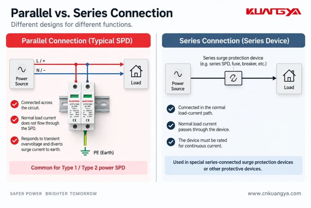
La tabella sottostante mostra come un tipico SPD collegato in parallelo differisce da un dispositivo installato direttamente nel percorso della corrente di carico normale.
| Caratteristica | Tipico SPD in parallelo | Dispositivo collegato in serie |
|---|---|---|
| Collegato direttamente nel percorso di carico normale | No | Sì |
| La corrente di carico normale attraversa l'intero dispositivo | No | Sì |
| Configurazione comune per SPD di potenza di Tipo 1 / Tipo 2 | Sì | Meno comune |
| Scopo principale | Limita la sovratensione transitoria fornendo un percorso per la corrente di scarica | Dipende dal design del prodotto |
| La corrente nominale continua è critica per l'intero dispositivo | Solitamente non nello stesso modo di un dispositivo in linea | Sì |
| La lunghezza del cavo di installazione influisce sulla protezione | Sì | Internal arrangement may reduce external parallel lead-length effects |
| Applicazioni tipiche | Distribution boards, equipment entrances, PV systems | Selected sensitive loads or specialized protection/filtering applications |
The important point is not that one method is universally “good” and the other is “bad.”
They are different product architectures.
For a normal DIN-rail power SPD, however, parallel connection is usually the expected installation method.
The same principle applies in many photovoltaic systems, where the SPD is connected in parallel with the DC circuit according to the manufacturer’s wiring configuration.
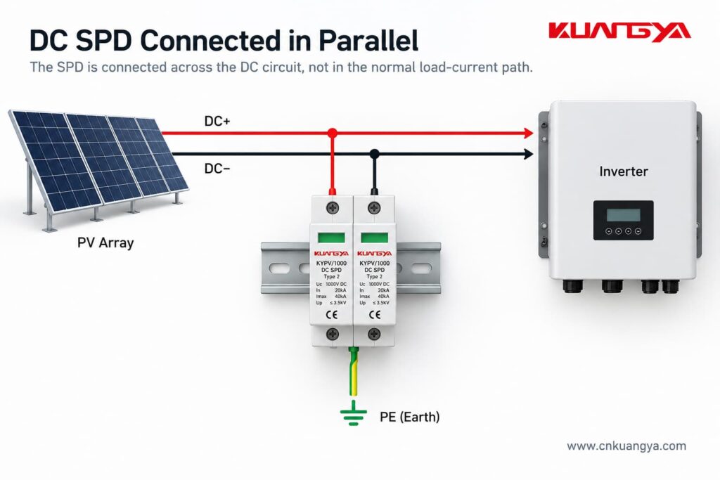
However, DC SPD wiring deserves extra care.
It is not correct to assume that every PV SPD is simply wired:
DC+ → SPD → PE
DC− → SPD → PE
The actual internal protection circuit may be different.
Depending on the product and PV system configuration, the SPD may provide protection modes between:
Different SPD circuit arrangements are used for different earthing systems and PV architectures.
For a PV SPD connected in parallel, the exact terminal arrangement still depends on the SPD design, system topology, and manufacturer wiring diagram.
This is why the wiring diagram printed on the SPD or provided in the manufacturer’s installation instructions is so important.
For photovoltaic DC applications, the dedicated IEC product standard is IEC 61643-31. DEHN also identifies IEC 60364-7-712 and IEC 60364-5-53 among the relevant installation standards for PV and low-voltage SPD applications.
Although AC and DC SPDs are based on similar surge-protection principles, the systems are not interchangeable.
DC systems present additional challenges because direct current has no natural zero crossing, which makes interruption of DC arcs more difficult.
For this reason, the SPD must be specifically suitable for the DC voltage, system configuration and application.
Always check:
before installation.
Using a KUANGYA KYPV/1000 Type 2 DC SPD as an example, the nameplate may include parameters such as:
These values describe different parts of the SPD’s electrical performance.
Uc is the maximum continuous operating voltage specified for the SPD.
The system voltage and possible operating conditions must be considered when choosing a suitable voltage rating.
In is the nominal discharge current.
For a Type 2 SPD, it is associated with an 8/20 μs impulse-current waveform.
Imax is the maximum discharge current specified for the SPD, also associated with the 8/20 μs waveform for this type of device.
Imax is equal to or greater than In.
Up is the voltage protection level.
It indicates the voltage-limiting performance of the SPD under specified test conditions.
The key point for today’s topic is this:
20 kA In and 40 kA Imax do not mean that 20 kA or 40 kA continuously flows through the SPD during normal operation.
These are transient surge-current parameters.
That is another reason why comparing an SPD’s In or Imax directly with the load current of an inverter is incorrect.
No.
In fact, connection length is extremely important for a parallel-connected SPD.
A surge has a very fast current rise.
The connecting conductors therefore have inductance, and the rapidly changing surge current can create an additional voltage drop along those conductors.
That additional voltage is effectively added to the voltage experienced by the protected equipment.
Secondo NEMA’s guidance on hard-wired SPD installation, the size and length of the connecting leads can affect the performance of a parallel-connected SPD, and short, direct connections are preferred.
Phoenix Contact makes the same point: long connecting conductors can increase the effective voltage protection level seen in the installation.
So even if two installations use exactly the same SPD, their real-world protection performance may not be identical if one has much longer connection conductors.
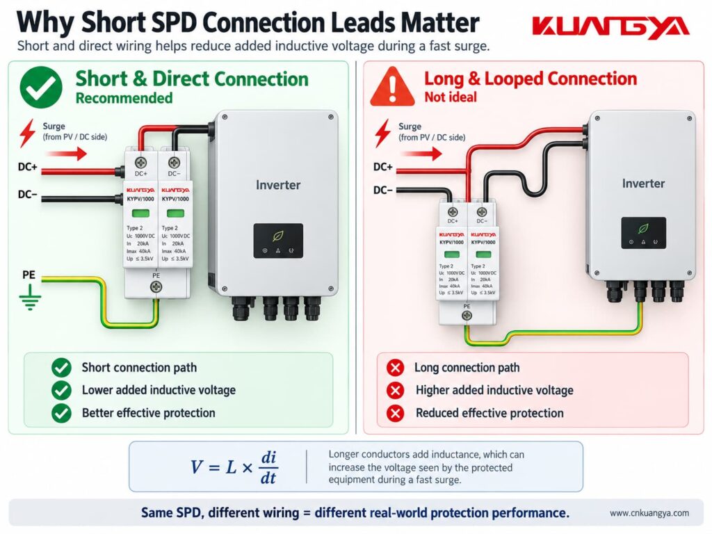
The SPD connection should generally be:
This is also why SPD location matters.
If you want to understand this issue in more detail, see our guide:
La distanza tra l'SPD e l'inverter è rilevante?
The exact position depends on the system being protected.
For example, an SPD may be installed:
If your inverter already includes surge protection, do not assume that an additional external SPD is automatically unnecessary. See L'inverter solare è dotato di un SPD CC integrato: è ancora necessario un SPD esterno?
The objective is not simply to put “one SPD somewhere in the system.”
The SPD should be positioned as part of a coordinated protection concept.
For PV systems in particular, cable length and the location of the inverter, modules and building entry points can affect whether additional SPDs are appropriate.
Secondo DEHN’s photovoltaic surge protection guidance, SPDs should be installed as close as possible to the equipment being protected, such as the inverter, on both the AC and DC sides.
The specific requirements should always be determined from the applicable installation standard, risk assessment and manufacturer instructions.
Sometimes yes, but not always in exactly the same way.
This is another area where oversimplified advice can cause problems.
A parallel SPD may require an external:
depending on the SPD design and installation.
Other SPDs may include internal protective or disconnecting components.
The correct arrangement depends on factors such as:
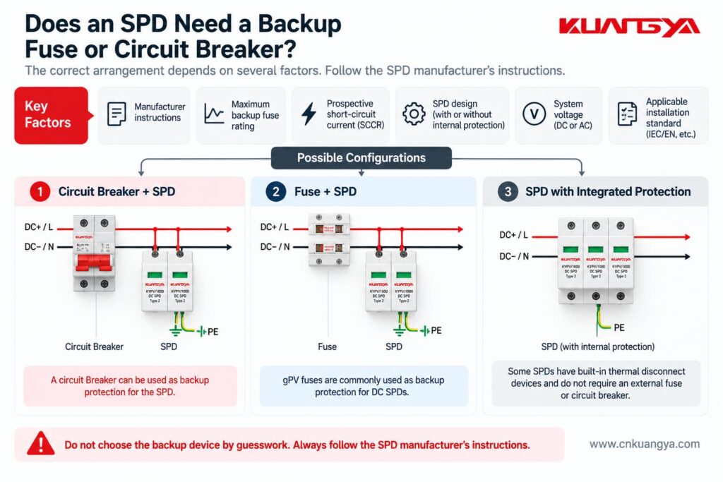
NEMA specifically advises installers to follow the manufacturer’s requirements regarding fuses, breakers and connection leads.
Therefore, do not assume:
“Every SPD needs exactly the same backup breaker.”
And do not assume:
“Because the SPD is connected in parallel, no overcurrent protection is ever required.”
Entrambe le affermazioni possono essere errate.
Always check the SPD datasheet and installation instructions.
Imagine two identical SPDs.
The SPD is mounted very close to the protected equipment, with short and direct conductors.
The SPD is several meters away and connected through long conductors.
Although the SPD nameplate is identical, the effective protection at the equipment can be different.
This happens because the connecting conductors contribute additional inductive voltage during a fast surge.
NEMA explains this relationship using:
V = L × di/dt
where:
The faster the current changes and the more inductance there is in the connection, the greater the additional voltage can become.
You do not need to calculate this formula for every normal installation.
La lezione pratica è molto più semplice:
Keep SPD connections short and direct.
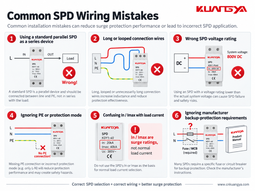
Understanding why the SPD is connected in parallel also makes several common installation mistakes easier to recognize.
Do not simply place a normal parallel DIN-rail SPD in the main load path unless the manufacturer’s design specifically requires that configuration.
Follow the wiring diagram for the exact product.
A good SPD with poor wiring may provide worse protection than expected.
Long leads increase inductive voltage during a surge.
Short and direct routing is generally preferred.
Do not assume every surge simply flows from one line terminal to earth.
The protection modes depend on the electrical network and SPD design.
Correct PE, bonding and circuit connections are essential where required by the product and installation design.
An SPD must be suitable for the voltage that can continuously appear at its terminals.
This is particularly important in PV systems, where string open-circuit voltage changes with temperature.
Choosing an SPD only because it says “DC SPD” is not enough.
The voltage rating must match the actual PV system design.
For a step-by-step method, see our DC SPD voltage selection guide for solar PV systems.
This is one of the most common misunderstandings.
An SPD marked:
In = 20 kA
does not mean:
Normal load current = 20 kA
In and Imax describe surge-current performance under specified impulse conditions.
They are not normal operating-current ratings.
Do not guess the fuse or breaker size.
Different SPD designs can have different backup protection requirements.
Some products also include integrated protective components.
Check the actual product documentation.
Many modular SPDs include a visual status indicator.
If the indicator shows a fault or replacement condition, the protection module may need to be replaced.
Some SPDs also have remote signaling contacts for connection to alarms, PLCs or monitoring systems.
Installing the SPD is only the first step.
Its condition should also be checked during maintenance.
For common warning signs and replacement indicators, see How to Know If an SPD Is Bad?
A circuit breaker and an SPD protect against different electrical problems.
A circuit breaker is mainly intended to interrupt abnormal current conditions such as overloads or short circuits.
Because it must sense and interrupt circuit current, it is connected in series with the load.
An SPD is intended to limit transient overvoltage.
A typical power SPD is connected in parallel so that it can conduct surge current when the transient voltage rises.
That means:
Circuit breaker → current protection
SPD → transient overvoltage protection
One cannot normally replace the other.
They perform different jobs.
The same principle applies to a fuse.
A fuse is installed in series with the circuit it protects.
Normal load current passes through the fuse element.
If excessive current persists, the fuse element opens the circuit.
A typical SPD behaves differently.
It remains connected across the protected circuit and responds mainly when the voltage reaches a level that causes its protective elements to conduct.
So although fuses, breakers and SPDs may all appear in the same electrical panel, their functions and connection methods are not the same.
Most common Type 1 and Type 2 power SPDs used in distribution boards and similar applications are connected in parallel with the circuit they protect.
However, specially designed series-connected SPDs and surge filters also exist.
Always follow the wiring instructions for the exact product.
A typical SPD is connected in parallel because it does not need to carry the normal load current.
During normal voltage conditions, it remains in a high-impedance state.
When a transient overvoltage occurs, it conducts surge current through its protection path and limits the voltage across the protected equipment.
The normal load current does not normally flow through a typical parallel-connected SPD.
However, a small leakage or operating current may exist depending on the SPD technology and design.
Therefore, saying “absolutely no current flows through an SPD” would not be technically precise.
Non necessariamente.
An SPD may operate between line and neutral, line and earth, neutral and earth, line and line, or different DC conductors depending on its protection modes.
The exact surge-current path depends on the SPD and electrical system configuration.
Many power SPDs are designed to be connected in parallel across the appropriate conductors of the supply.
However, the exact wiring arrangement depends on the SPD type, system earthing arrangement, required overcurrent protection and manufacturer instructions.
Never determine the connection from a generic diagram alone.
A normal parallel SPD is not designed to serve as the continuous main load-current path.
Installing an inline device requires a product specifically designed for that purpose, including suitable current, terminal, fault and thermal ratings.
No.
In and Imax are surge-discharge current parameters.
They should not be confused with PV string operating current, short-circuit current or inverter input current.
The general surge-protection principle is similar, but DC and AC systems have important differences.
The voltage rating, polarity, protection modes, earthing arrangement and internal SPD design may differ.
For PV systems, always use an SPD intended for the specific DC application and follow its wiring diagram.
It depends on the protection mode and system design.
Many power SPDs include protection paths involving PE, but not every surge protection mode is simply conductor-to-earth.
Use the manufacturer’s circuit diagram and the applicable earthing and bonding requirements.
Sì.
Long SPD connection conductors add inductance and can increase the voltage experienced by the protected equipment during a fast transient.
For this reason, connection conductors should generally be kept as short and direct as practical.
If you only remember a few things from this article, remember these:
So, why is an SPD connected in parallel instead of series?
For a typical Type 1 or Type 2 SPD collegato in parallelo, the normal load current does not pass through the SPD as it would through a series-connected device.
Under normal operating conditions, the SPD remains largely in standby.
When a surge occurs, it conducts through its designed protection path and helps limit the voltage appearing across the protected equipment.
That is fundamentally different from a fuse or circuit breaker, which normally carries the circuit current and is therefore installed in series.
However, correct SPD installation involves more than simply choosing “parallel.”
The SPD voltage rating, protection modes, location, conductor length, earthing and bonding arrangement, backup protection and manufacturer wiring diagram all affect the final protection performance.
For solar PV systems in particular, always use an SPD designed for the relevant DC application and verify the actual system voltage and wiring configuration before installation.

