WengYang Industrial Zone Yueqing Wenzhou 325000
Work Hours
Monday to Friday: 7AM - 7PM
Weekend: 10AM - 5PM
WengYang Industrial Zone Yueqing Wenzhou 325000
Work Hours
Monday to Friday: 7AM - 7PM
Weekend: 10AM - 5PM

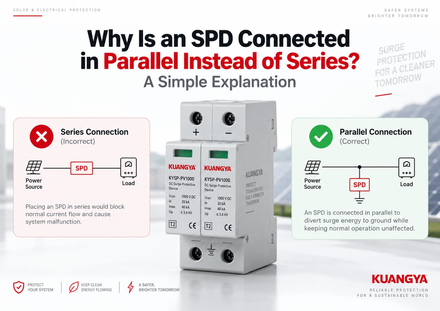
If you look at a typical surge protective device (SPD) installation, you may notice something different from a fuse or circuit breaker.
A fuse or circuit breaker is normally installed in series with the circuit, so the load current passes through it.
A typical power SPD is usually connected in parallel with the circuit it protects, which is why many installers ask why an SPD is connected in parallel instead of series.
Why?
The simple answer is that a parallel-connected SPD does not need to carry the normal load current. Under normal operating conditions, it remains in a high-impedance state. When a transient overvoltage occurs, the SPD begins conducting and provides a low-impedance path for surge current, limiting the voltage reaching the protected equipment.
This is why parallel connection is widely used for Type 1 and Type 2 SPDs in power distribution and photovoltaic systems.
However, “SPD = always parallel” is not an absolute rule. Series-connected SPDs and surge filters also exist for certain applications. In this article, we are mainly talking about the common parallel-connected power SPD used in AC distribution and solar PV DC systems.
A typical SPD connected in parallel is designed to respond to temporary overvoltage events without carrying the normal operating current of the load.
Under normal conditions:
Power source → Load
The SPD remains in standby.
When a surge occurs, the SPD changes its electrical behavior and conducts surge current through its protection path, helping limit the voltage appearing across sensitive equipment.
A simplified parallel arrangement looks like this:
Power Source ───────────── Load
       │
       │
      SPD
       │
Protection Path
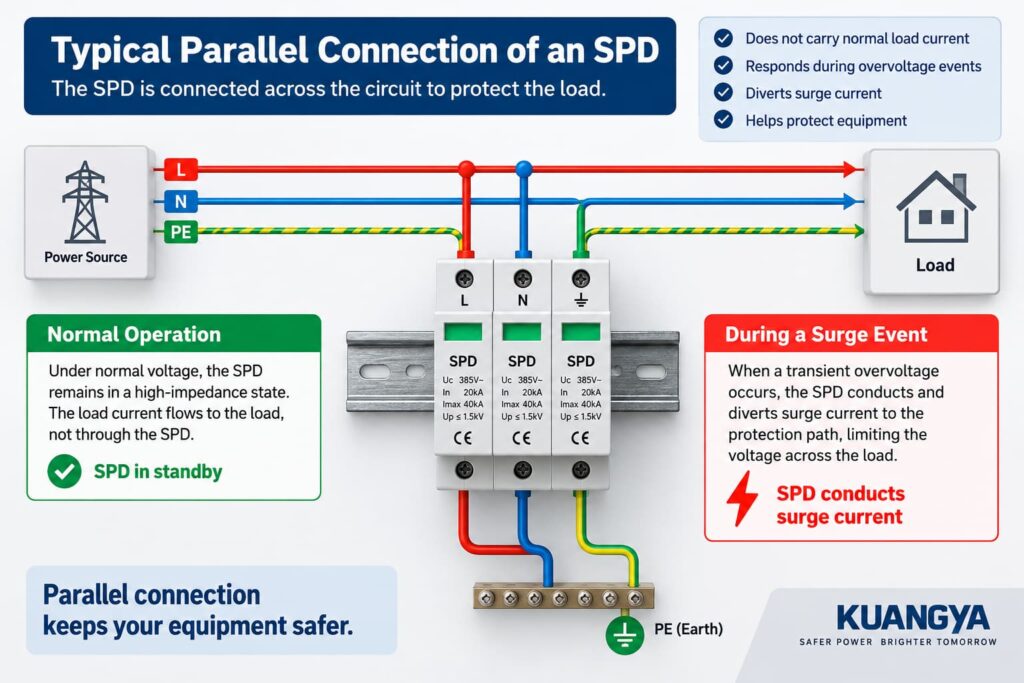
The SPD is connected across the circuit rather than inserted directly into the normal load-current path. Phoenix Contact’s surge protection fundamentals also explains that SPDs can be installed in parallel with the protected equipment or between the relevant conductors.
Eaton describes parallel, or shunt-connected, SPDs in the same way: their connecting conductors do not carry the normal supply current, but instead carry short-duration current associated with transient events.
That basic difference explains why most common power SPDs are installed in parallel.
To understand the parallel connection, it helps to first understand what the SPD is doing when there is no surge.
During normal operation, the system voltage remains below the level at which the SPD significantly conducts.
For an MOV-based SPD, the protection element presents a relatively high impedance under normal voltage conditions.
This means the main operating current continues through the normal power circuit to the load.
The SPD is essentially standing by.
A simplified view is:
Supply ───────────────── Load
          Normal current

        │
       SPD
        │
     Standby
This does not necessarily mean absolutely zero current flows through every SPD. Depending on the SPD technology and design, a small leakage or operating current can exist.
The important point is:
The normal load current does not need to flow through a typical parallel-connected SPD.
Think of the SPD as a protection path waiting beside the main circuit rather than a component that must continuously carry the equipment’s operating current.
A surge is a short-duration increase in voltage that may be caused by events such as lightning-related transients or switching operations.
When the voltage across the SPD rises sufficiently, the SPD’s protection elements begin conducting.
If you want a deeper explanation of how the protection elements respond to transient overvoltage, see our guide on how a DC SPD works.
Its impedance decreases sharply compared with the normal condition.
This allows surge current to flow through the available protection path and limits the transient voltage appearing across the protected equipment.
A simplified representation is:
                 Equipment
Power ────────────────►
       │
       │ Surge current
       ▼
      SPD
       │
       ▼
Protection / bonding path
However, this diagram is only a simplified example.
An SPD does not always divert every surge directly to earth.
Depending on the electrical system and the SPD design, protection modes may exist between:
For this reason, it is more accurate to say:
The SPD provides a controlled path for surge current and limits the transient voltage across the equipment it protects.
The exact current path depends on the SPD configuration and system topology.
To understand why an SPD is connected in parallel, it helps to look at what happens during both normal operation and a surge event.
There are several important reasons why an SPD connected in parallel is widely used in power distribution systems.
This is one of the biggest differences between an SPD and devices such as a circuit breaker or fuse.
Imagine that an inverter normally operates at tens of amps.
With a typical parallel-connected SPD, that operating current does not have to continuously pass through the SPD.
Instead:
Source ───────────────── Load
         │
        SPD
The SPD is connected across the protected circuit.
This means the SPD can be selected primarily according to surge-protection requirements rather than according to the full operating current of every downstream load.
Phoenix Contact similarly notes that its parallel-installed power SPDs appear electrically as a branch connected across the power distribution system rather than carrying the circuit’s normal ampacity.
A typical SPD is voltage-sensitive.
During normal system voltage, it remains largely inactive.
When a transient voltage rises beyond its normal operating region, the protection elements begin conducting.
That is fundamentally different from a fuse, circuit breaker, or isolating switch.
For example:
Fuse
Source → Fuse → Load
Circuit breaker
Source → Breaker → Load
Typical parallel SPD
Source ────────── Load
       │
       SPD
       │
A fuse or breaker must normally carry the circuit current because it is physically in the load path.
A parallel SPD does not.
The purpose of an SPD is not to “block” every surge before it reaches the load.
Instead, a voltage-limiting SPD responds to the increasing transient voltage and conducts surge current.
This action limits the voltage across the protected circuit.
For example, in a simplified PV system:
PV Array ───────────────── Inverter
          │
         SPD
          │
   Protection Path
During normal operation, the PV power continues toward the inverter.
During a surge event, the SPD conducts according to its protection mode and helps keep the transient voltage within a lower level than it would otherwise reach.
This is the basic reason the SPD is placed across the circuit.
Because the typical SPD is connected as a parallel branch, it does not become the normal conductive path between the source and the load.
That has an important practical advantage.
The system’s normal operating current does not depend on continuously passing through the SPD protection elements.
Of course, this does not mean an SPD can be ignored after installation.
SPDs can degrade or disconnect after abnormal electrical stress, so their status indication should still be checked periodically.
Understanding why an SPD is connected in parallel also helps explain why a typical shunt-connected SPD is not placed in series with the normal load path.
Circuit breakers and fuses are normally installed in series because they must carry the circuit current. A typical parallel SPD is designed for a different function.
A true series connection looks like this:
Source → Device → Load
If the complete SPD assembly were inserted into the load path, the SPD would need to accommodate the continuous load current.
Its conductors, terminals, thermal design, short-circuit performance and failure behavior would all have to be designed for that application.
That is not how the common DIN-rail Type 1 or Type 2 parallel SPD is normally used.
This is an especially important point when reading an SPD nameplate.
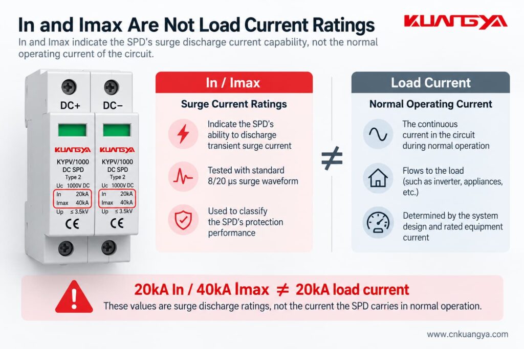
Suppose an SPD is marked:
In = 20 kA
and
Imax = 40 kA
If these SPD ratings are still confusing, our DC SPD specifications guide explains Ucpv, In, Imax, Up and Iscpv in more detail.
These numbers do not mean the SPD is designed to continuously carry 20 kA or 40 kA of normal load current.
For Type 2 SPDs, In refers to the nominal discharge current associated with an 8/20 μs current impulse, while Imax refers to the maximum discharge current associated with an 8/20 μs impulse.
Phoenix Contact’s technical definitions likewise describe In and Imax as impulse-current values flowing through the SPD, not normal continuous load-current ratings.
So:
In and Imax are surge discharge current ratings. They are not the normal operating current of the load.
This distinction is very important when selecting or explaining an SPD.
No.
This is an important exception.
Although the common Type 1 and Type 2 power SPDs discussed in this article are generally installed in parallel, series-connected SPD assemblies and series-connected surge filters also exist.
Schneider Electric notes that series-connected products are commonly installed inline near particular loads, while parallel-connected SPDs are the more common arrangement at switchboards and distribution panels.
A series-connected product has to be designed specifically to carry the circuit’s load current.
Therefore, it would be incorrect to say:
“An SPD can never be connected in series.”
A more technically accurate statement is:
Most common power-distribution Type 1 and Type 2 SPDs are connected in parallel, while specially designed series-connected surge protection products also exist for particular applications.
For solar PV and general distribution-board applications, always follow the actual SPD manufacturer’s wiring diagram.
The table below shows how a typical SPD connected in parallel differs from a device installed directly in the normal load-current path.
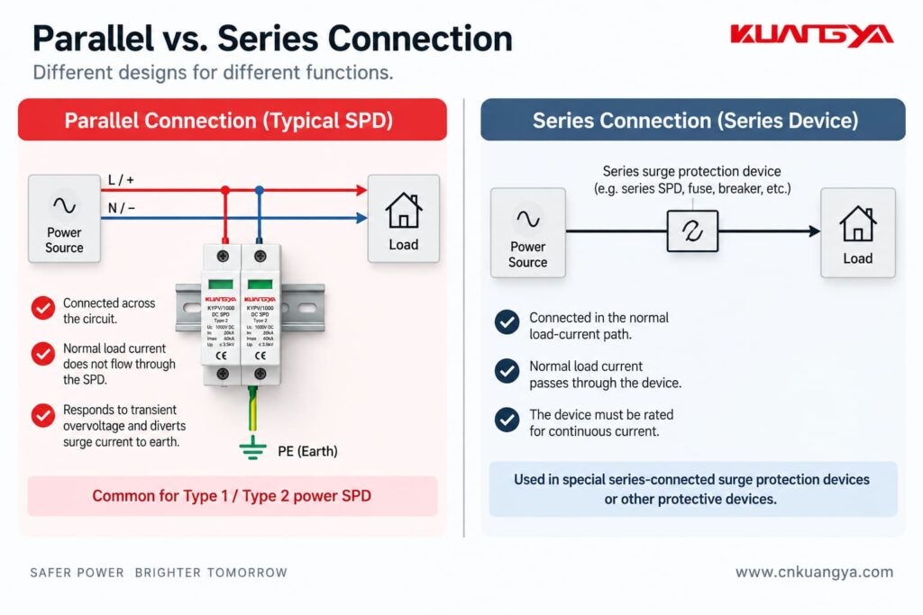
| Feature | Typical Parallel SPD | Series-Connected Device |
|---|---|---|
| Connected directly in normal load path | No | Yes |
| Normal load current passes through complete device | No | Yes |
| Common arrangement for Type 1 / Type 2 power SPD | Yes | Less common |
| Main purpose | Limit transient overvoltage by providing a surge-current path | Depends on product design |
| Continuous current rating critical to complete device | Usually not in the same way as an inline device | Yes |
| Installation lead length affects protection | Yes | Internal arrangement may reduce external parallel lead-length effects |
| Typical applications | Distribution boards, equipment entrances, PV systems | Selected sensitive loads or specialized protection/filtering applications |
The important point is not that one method is universally “good” and the other is “bad.”
They are different product architectures.
For a normal DIN-rail power SPD, however, parallel connection is usually the expected installation method.
The same principle applies in many photovoltaic systems, where the SPD is connected in parallel with the DC circuit according to the manufacturer’s wiring configuration.
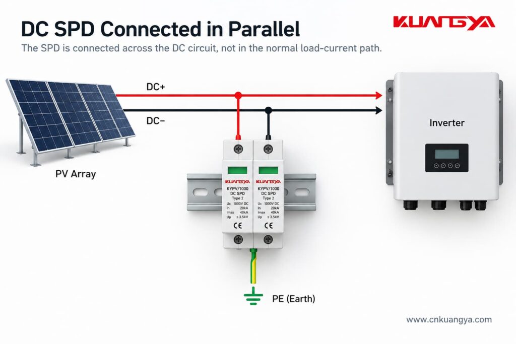
However, DC SPD wiring deserves extra care.
It is not correct to assume that every PV SPD is simply wired:
DC+ → SPD → PE
DC− → SPD → PE
The actual internal protection circuit may be different.
Depending on the product and PV system configuration, the SPD may provide protection modes between:
Different SPD circuit arrangements are used for different earthing systems and PV architectures.
For a PV SPD connected in parallel, the exact terminal arrangement still depends on the SPD design, system topology, and manufacturer wiring diagram.
This is why the wiring diagram printed on the SPD or provided in the manufacturer’s installation instructions is so important.
For photovoltaic DC applications, the dedicated IEC product standard is IEC 61643-31. DEHN also identifies IEC 60364-7-712 and IEC 60364-5-53 among the relevant installation standards for PV and low-voltage SPD applications.
Although AC and DC SPDs are based on similar surge-protection principles, the systems are not interchangeable.
DC systems present additional challenges because direct current has no natural zero crossing, which makes interruption of DC arcs more difficult.
For this reason, the SPD must be specifically suitable for the DC voltage, system configuration and application.
Always check:
before installation.
Using a KUANGYA KYPV/1000 Type 2 DC SPD as an example, the nameplate may include parameters such as:
These values describe different parts of the SPD’s electrical performance.
Uc is the maximum continuous operating voltage specified for the SPD.
The system voltage and possible operating conditions must be considered when choosing a suitable voltage rating.
In is the nominal discharge current.
For a Type 2 SPD, it is associated with an 8/20 μs impulse-current waveform.
Imax is the maximum discharge current specified for the SPD, also associated with the 8/20 μs waveform for this type of device.
Imax is equal to or greater than In.
Up is the voltage protection level.
It indicates the voltage-limiting performance of the SPD under specified test conditions.
The key point for today’s topic is this:
20 kA In and 40 kA Imax do not mean that 20 kA or 40 kA continuously flows through the SPD during normal operation.
These are transient surge-current parameters.
That is another reason why comparing an SPD’s In or Imax directly with the load current of an inverter is incorrect.
No.
In fact, connection length is extremely important for a parallel-connected SPD.
A surge has a very fast current rise.
The connecting conductors therefore have inductance, and the rapidly changing surge current can create an additional voltage drop along those conductors.
That additional voltage is effectively added to the voltage experienced by the protected equipment.
According to NEMA’s guidance on hard-wired SPD installation, the size and length of the connecting leads can affect the performance of a parallel-connected SPD, and short, direct connections are preferred.
Phoenix Contact makes the same point: long connecting conductors can increase the effective voltage protection level seen in the installation.
So even if two installations use exactly the same SPD, their real-world protection performance may not be identical if one has much longer connection conductors.
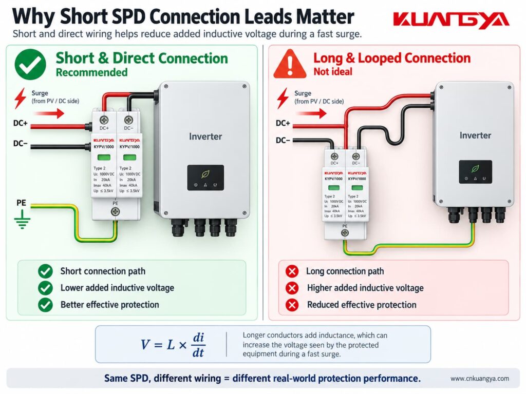
The SPD connection should generally be:
This is also why SPD location matters.
If you want to understand this issue in more detail, see our guide:
Does the Distance Between the SPD and Inverter Matter?
The exact position depends on the system being protected.
For example, an SPD may be installed:
If your inverter already includes surge protection, do not assume that an additional external SPD is automatically unnecessary. See Solar Inverter Has a Built-In DC SPD: Do You Still Need an External SPD?
The objective is not simply to put “one SPD somewhere in the system.”
The SPD should be positioned as part of a coordinated protection concept.
For PV systems in particular, cable length and the location of the inverter, modules and building entry points can affect whether additional SPDs are appropriate.
According to DEHN’s photovoltaic surge protection guidance, SPDs should be installed as close as possible to the equipment being protected, such as the inverter, on both the AC and DC sides.
The specific requirements should always be determined from the applicable installation standard, risk assessment and manufacturer instructions.
Sometimes yes, but not always in exactly the same way.
This is another area where oversimplified advice can cause problems.
A parallel SPD may require an external:
depending on the SPD design and installation.
Other SPDs may include internal protective or disconnecting components.
The correct arrangement depends on factors such as:
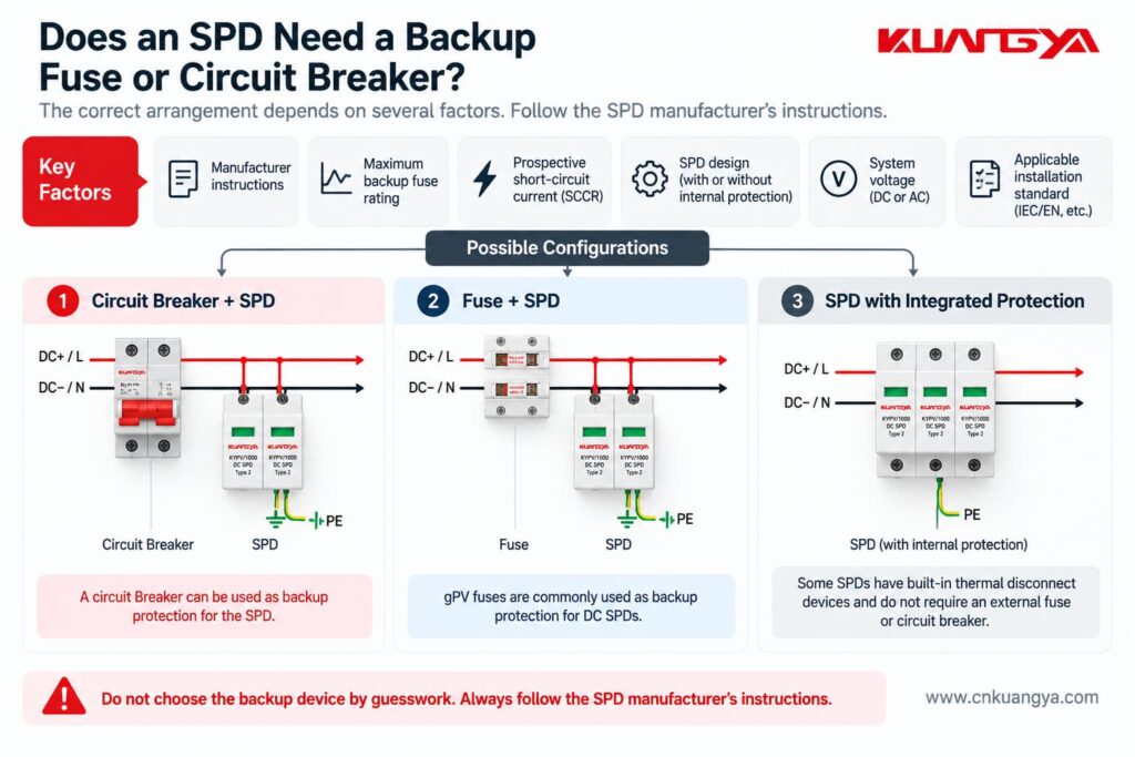
NEMA specifically advises installers to follow the manufacturer’s requirements regarding fuses, breakers and connection leads.
Therefore, do not assume:
“Every SPD needs exactly the same backup breaker.”
And do not assume:
“Because the SPD is connected in parallel, no overcurrent protection is ever required.”
Both statements can be wrong.
Always check the SPD datasheet and installation instructions.
Imagine two identical SPDs.
The SPD is mounted very close to the protected equipment, with short and direct conductors.
The SPD is several meters away and connected through long conductors.
Although the SPD nameplate is identical, the effective protection at the equipment can be different.
This happens because the connecting conductors contribute additional inductive voltage during a fast surge.
NEMA explains this relationship using:
V = L × di/dt
where:
The faster the current changes and the more inductance there is in the connection, the greater the additional voltage can become.
You do not need to calculate this formula for every normal installation.
The practical lesson is much simpler:
Keep SPD connections short and direct.
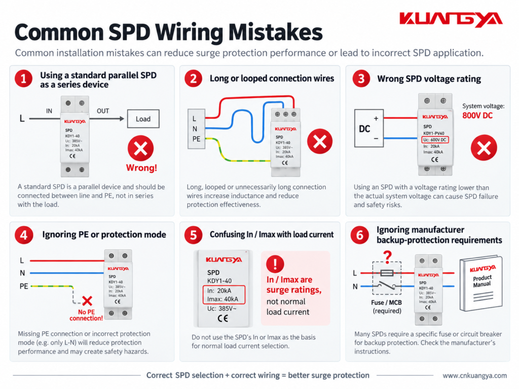
Understanding why the SPD is connected in parallel also makes several common installation mistakes easier to recognize.
Do not simply place a normal parallel DIN-rail SPD in the main load path unless the manufacturer’s design specifically requires that configuration.
Follow the wiring diagram for the exact product.
A good SPD with poor wiring may provide worse protection than expected.
Long leads increase inductive voltage during a surge.
Short and direct routing is generally preferred.
Do not assume every surge simply flows from one line terminal to earth.
The protection modes depend on the electrical network and SPD design.
Correct PE, bonding and circuit connections are essential where required by the product and installation design.
An SPD must be suitable for the voltage that can continuously appear at its terminals.
This is particularly important in PV systems, where string open-circuit voltage changes with temperature.
Choosing an SPD only because it says “DC SPD” is not enough.
The voltage rating must match the actual PV system design.
For a step-by-step method, see our DC SPD voltage selection guide for solar PV systems.
This is one of the most common misunderstandings.
An SPD marked:
In = 20 kA
does not mean:
Normal load current = 20 kA
In and Imax describe surge-current performance under specified impulse conditions.
They are not normal operating-current ratings.
Do not guess the fuse or breaker size.
Different SPD designs can have different backup protection requirements.
Some products also include integrated protective components.
Check the actual product documentation.
Many modular SPDs include a visual status indicator.
If the indicator shows a fault or replacement condition, the protection module may need to be replaced.
Some SPDs also have remote signaling contacts for connection to alarms, PLCs or monitoring systems.
Installing the SPD is only the first step.
Its condition should also be checked during maintenance.
For common warning signs and replacement indicators, see How to Know If an SPD Is Bad?
A circuit breaker and an SPD protect against different electrical problems.
A circuit breaker is mainly intended to interrupt abnormal current conditions such as overloads or short circuits.
Because it must sense and interrupt circuit current, it is connected in series with the load.
An SPD is intended to limit transient overvoltage.
A typical power SPD is connected in parallel so that it can conduct surge current when the transient voltage rises.
That means:
Circuit breaker → current protection
SPD → transient overvoltage protection
One cannot normally replace the other.
They perform different jobs.
The same principle applies to a fuse.
A fuse is installed in series with the circuit it protects.
Normal load current passes through the fuse element.
If excessive current persists, the fuse element opens the circuit.
A typical SPD behaves differently.
It remains connected across the protected circuit and responds mainly when the voltage reaches a level that causes its protective elements to conduct.
So although fuses, breakers and SPDs may all appear in the same electrical panel, their functions and connection methods are not the same.
Most common Type 1 and Type 2 power SPDs used in distribution boards and similar applications are connected in parallel with the circuit they protect.
However, specially designed series-connected SPDs and surge filters also exist.
Always follow the wiring instructions for the exact product.
A typical SPD is connected in parallel because it does not need to carry the normal load current.
During normal voltage conditions, it remains in a high-impedance state.
When a transient overvoltage occurs, it conducts surge current through its protection path and limits the voltage across the protected equipment.
The normal load current does not normally flow through a typical parallel-connected SPD.
However, a small leakage or operating current may exist depending on the SPD technology and design.
Therefore, saying “absolutely no current flows through an SPD” would not be technically precise.
Not necessarily.
An SPD may operate between line and neutral, line and earth, neutral and earth, line and line, or different DC conductors depending on its protection modes.
The exact surge-current path depends on the SPD and electrical system configuration.
Many power SPDs are designed to be connected in parallel across the appropriate conductors of the supply.
However, the exact wiring arrangement depends on the SPD type, system earthing arrangement, required overcurrent protection and manufacturer instructions.
Never determine the connection from a generic diagram alone.
A normal parallel SPD is not designed to serve as the continuous main load-current path.
Installing an inline device requires a product specifically designed for that purpose, including suitable current, terminal, fault and thermal ratings.
No.
In and Imax are surge-discharge current parameters.
They should not be confused with PV string operating current, short-circuit current or inverter input current.
The general surge-protection principle is similar, but DC and AC systems have important differences.
The voltage rating, polarity, protection modes, earthing arrangement and internal SPD design may differ.
For PV systems, always use an SPD intended for the specific DC application and follow its wiring diagram.
It depends on the protection mode and system design.
Many power SPDs include protection paths involving PE, but not every surge protection mode is simply conductor-to-earth.
Use the manufacturer’s circuit diagram and the applicable earthing and bonding requirements.
Yes.
Long SPD connection conductors add inductance and can increase the voltage experienced by the protected equipment during a fast transient.
For this reason, connection conductors should generally be kept as short and direct as practical.
If you only remember a few things from this article, remember these:
So, why is an SPD connected in parallel instead of series?
For a typical Type 1 or Type 2 SPD connected in parallel, the normal load current does not pass through the SPD as it would through a series-connected device.
Under normal operating conditions, the SPD remains largely in standby.
When a surge occurs, it conducts through its designed protection path and helps limit the voltage appearing across the protected equipment.
That is fundamentally different from a fuse or circuit breaker, which normally carries the circuit current and is therefore installed in series.
However, correct SPD installation involves more than simply choosing “parallel.”
The SPD voltage rating, protection modes, location, conductor length, earthing and bonding arrangement, backup protection and manufacturer wiring diagram all affect the final protection performance.
For solar PV systems in particular, always use an SPD designed for the relevant DC application and verify the actual system voltage and wiring configuration before installation.

