Промышленная зона Вэньян Юэцин Вэньчжоу 325000
Рабочие часы
Понедельник - пятница: 7AM - 7PM
Выходные: 10AM - 5PM
Промышленная зона Вэньян Юэцин Вэньчжоу 325000
Рабочие часы
Понедельник - пятница: 7AM - 7PM
Выходные: 10AM - 5PM

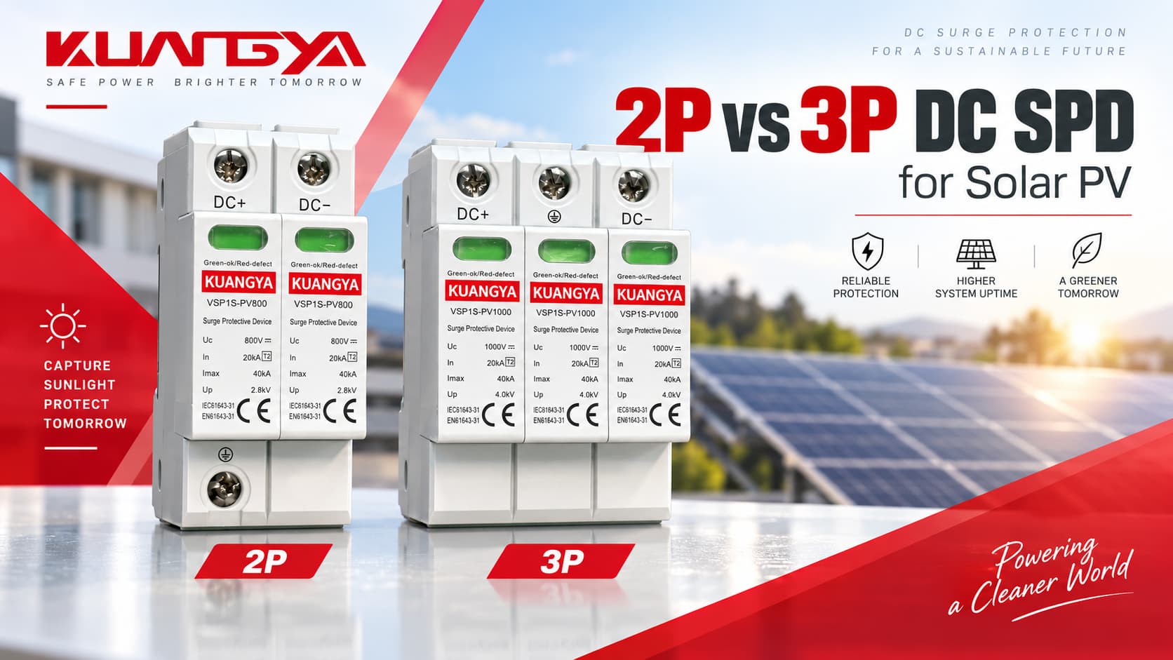
Выбор между УЗИП постоянного тока 2P и 3P для солнечных фотоэлектрических систем часто вызывает путаницу. Один из самых распространенных вопросов:
Следует ли использовать УЗИП постоянного тока 2P или 3P?
На первый взгляд ответ кажется простым. Фотоэлектрическая цепочка имеет положительный и отрицательный проводники постоянного тока, поэтому двухполюсного УЗИП может показаться достаточно. Тогда почему во многих устройствах защиты от перенапряжений для фотоэлектрических систем используются три защитных модуля или трехполюсная конфигурация?
Причина заключается в том, что Обозначения 2P и 3P не всегда описывают одну и ту же внутреннюю схему защиты у разных производителей..
Правильный выбор зависит от:
В данном руководстве объясняется разница между 2P и 3P УЗИП постоянного тока, приводятся реальные примеры от производителей и предлагается практический метод выбора для солнечных фотоэлектрических систем.
A 2P DC УЗИП не подходит автоматически только потому, что в цепи фотоэлектрической системы есть два активных проводника, и 3P DC УЗИП не является автоматически лучшим выбором только из-за наличия дополнительного модуля.
Правильный УЗИП должен быть выбран в соответствии с электрической топологией и одобренной производителем схемой подключения.
| Вопрос | Краткий ответ |
|---|---|
| Имеет ли фотоэлектрическая цепочка два активных проводника? | Обычно да: DC+ и DC− |
| Означает ли это всегда, что требуется 2P УЗИП? | Нет |
| Является ли третий модуль 3P УЗИП просто “полюсом PE”? | Не обязательно |
| Является ли 3P УЗИП мощнее, чем 2P УЗИП? | Не по своей сути |
| Можно ли взаимозаменять 2P и 3P УЗИП? | Только если производитель прямо допускает такую схему подключения |
| Что важнее всего? | Режимы защиты, система заземления, Ucpv, Iscpv и разрешенные схемы подключения |
| Какой стандарт распространяется на УЗИП для фотоэлектрических систем постоянного тока? | IEC 61643-31 |
| Какой стандарт регулирует выбор и применение УЗИП для фотоэлектрических систем? | IEC 61643-32 |
Самое безопасное правило:
Не выбирайте УЗИП для фотоэлектрических систем, основываясь только на количестве модулей. Изучите принципиальную схему производителя и убедитесь, что УЗИП одобрено для топологии вашей фотоэлектрической системы.
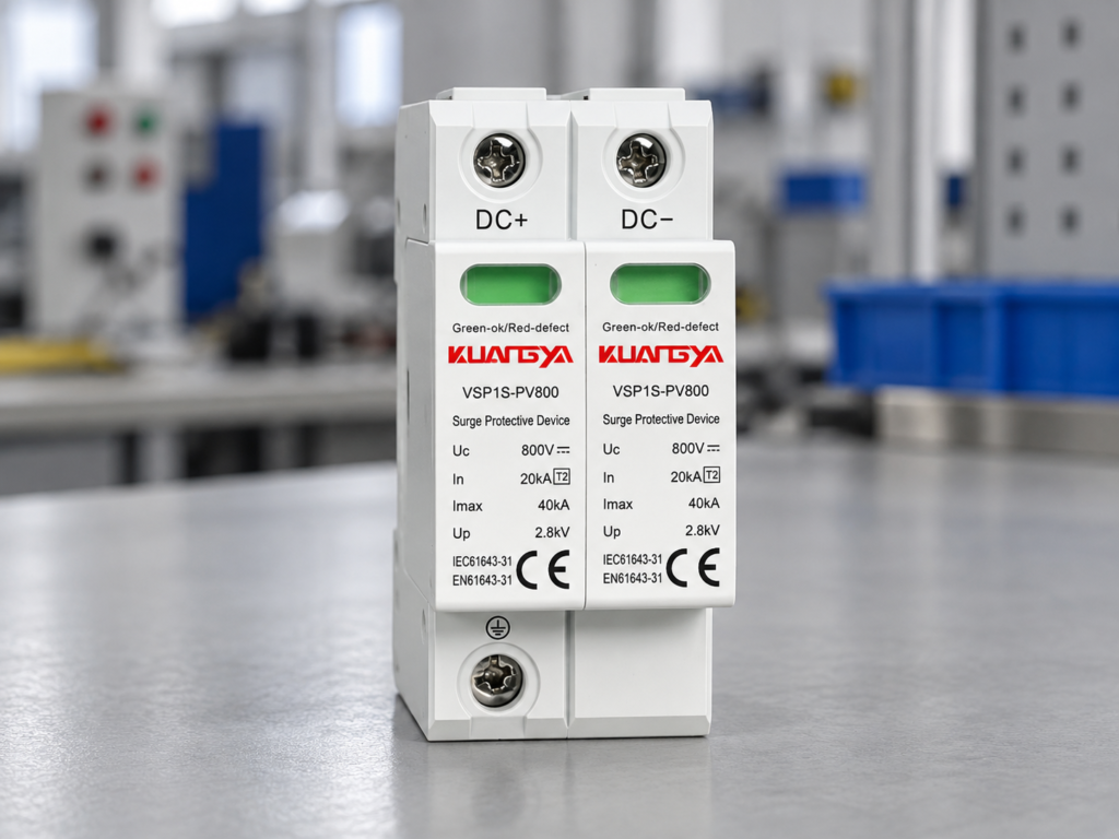
В повседневной электротехнической терминологии “P” обычно означает полюс.
Однако терминология УЗИП для фотоэлектрических систем менее однозначна, чем терминология автоматических выключателей.
В зависимости от производителя, в описании продукта могут упоминаться:
Эти термины взаимосвязаны, но они являются не всегда взаимозаменяемы.
Например, один производитель может описывать устройство как 2-полюсный УЗИП для фотоэлектрических систем, в то время как другое изделие, защищающее те же проводники DC+ и DC−, может физически содержать три сменных защитных элемента.
Это одна из главных причин, по которой покупателям не следует сравнивать УЗИП для фотоэлектрических систем только по внешнему виду.
Эти три понятия следует разделять.
| Срок | Что это описывает | Почему это важно |
|---|---|---|
| Защищаемый проводник | Защищаемый электрический проводник | Обычно DC+ и DC− в фотоэлектрической цепи |
| Полюс/модуль | Физический или электрический элемент УЗИП | Терминология производителя |
| Режим защиты | Путь, по которому ограничивается импульсное перенапряжение | Определяет условия перенапряжения, при которых может работать УЗИП |
| Подключение защитного заземления (PE) | Подключение к защитному заземлению | Обеспечивает опорную точку/путь для отвода импульсных перенапряжений |
| Y-образная схема | Внутренняя защитная цепь, выполненная по Y-образной конфигурации | Часто встречается в УЗИП для фотоэлектрических систем |
| Базовое положение | Физическое расположение модуля на DIN-рейке | Не всегда соответствует количеству защищаемых проводников |
Это означает:
Два защищаемых проводника постоянного тока не обязательно требуют использования только двух физических картриджей УЗИП.
Тот же принцип применим и к стороне переменного тока: количество модулей само по себе не определяет внутреннюю схему, как объясняется в нашем Сравнение УЗИП 3+1 и 4+0.
Солнечные фотоэлектрические массивы создают ряд особых условий, которые отсутствуют в обычном распределительном щите 230/400 В переменного тока.
УЗИП для фотоэлектрических систем должен работать в условиях:
В отличие от переменного тока, постоянный ток не проходит через нулевое значение каждый полупериод.
По этой причине отключение при неисправностях и внутренняя конструкция УЗИП особенно важны на стороне постоянного тока.
IEC 61643-31 специально охватывает УЗИП, предназначенные для стороны постоянного тока фотоэлектрических установок напряжением до 1500 В ПОСТОЯННОГО ТОКА.
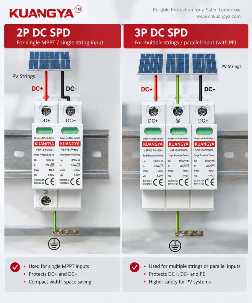
Фотоэлектрическому УЗИП может потребоваться ограничение напряжения между несколькими точками.
Типовые режимы защиты включают:
| Режим защиты | Описание |
|---|---|
| DC+ → PE | Импульс между положительным проводником и землей |
| DC− → PE | Перенапряжение между отрицательным проводником и землей |
| DC+ → DC− | Differential surge between the two DC conductors |
A correctly designed PV SPD can provide several of these protection paths through its internal network.
This is why looking only at the number of visible modules can be misleading.
For example, Phoenix Contact publishes PV SPDs using a Y configuration that provide protection modes between:
even though the manufacturer’s naming may refer to a “2+V” arrangement. Phoenix Contact lists these modes explicitly for its 1000 V PV devices.
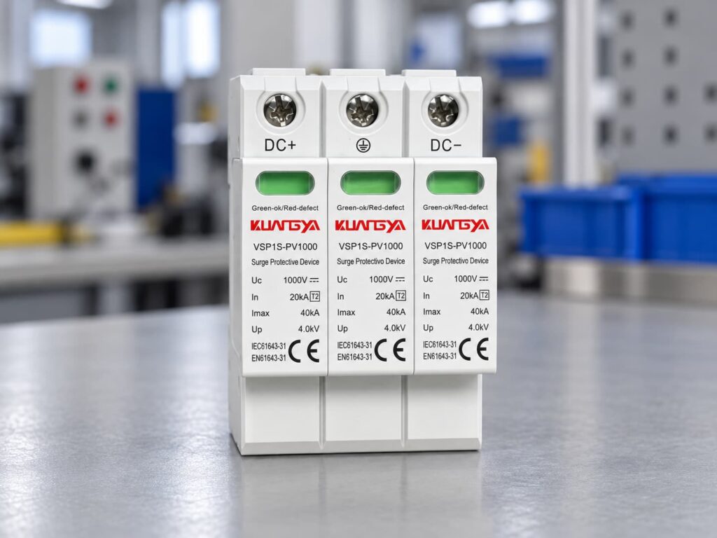
A Y-circuit is a common protective arrangement used in photovoltaic surge protection.
Instead of simply placing one MOV from positive to earth and another MOV from negative to earth, the SPD uses a coordinated internal network.
Conceptually:
DC+
↓
Protection element
↓
Common protection point
↓
Protection element
↓
PE
and another path connects the DC− conductor into the protective network.
The exact circuit varies by manufacturer.
The important point is that the internal network can provide protection for both:
while also addressing PV-specific fault conditions.
OBO, for example, describes its 1000 V PV surge protection solution as using an error-resistant Y circuit.
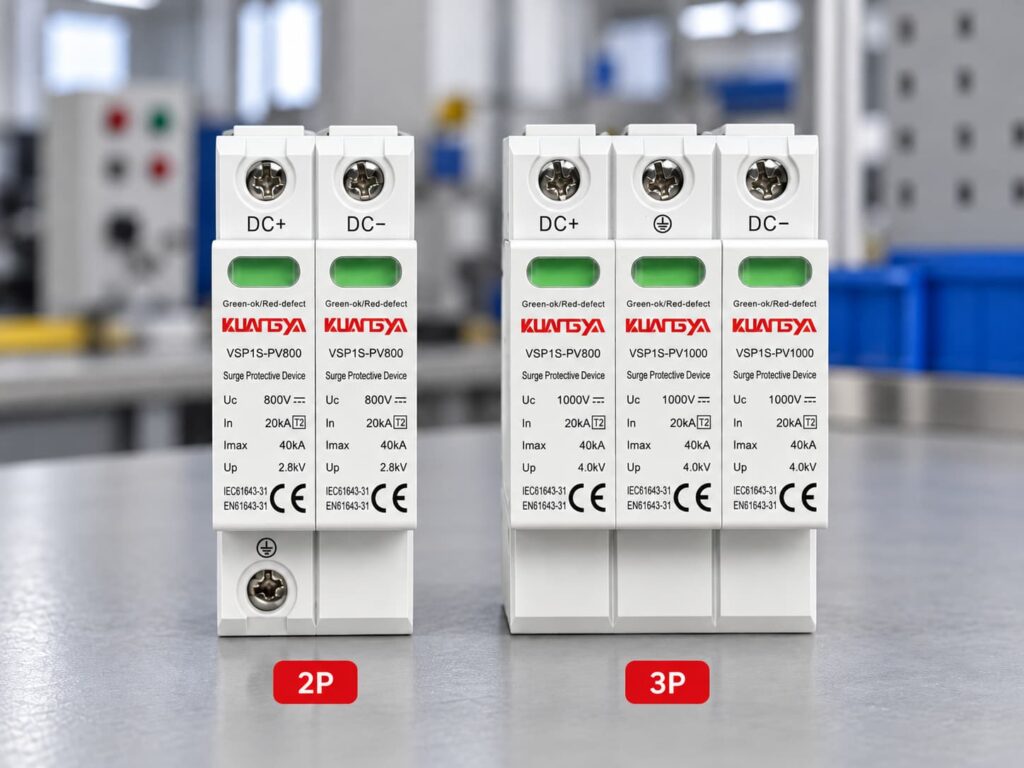
The following table provides a useful engineering comparison, but the manufacturer’s wiring diagram always takes priority.
| Характеристика | 2P DC SPD | 3P / Three-Module DC SPD |
|---|---|---|
| Physical size | Often smaller | Usually wider |
| Number of visible modules | Often 2 | Often 3 |
| DC conductors protected | Typically DC+ and DC− | Typically DC+ and DC− |
| Подключение защитного заземления (PE) | May be included | Usually included |
| Internal circuit | Depends on manufacturer | Often PV-specific Y circuit |
| Suitable for floating PV | Model-dependent | Common, but still model-dependent |
| Suitable for grounded PV | Model-dependent | Model-dependent |
| Differential protection | Check datasheet | Check datasheet |
| Common-mode protection | Check datasheet | Common on PV-specific designs |
| Стоимость | Often lower | Often slightly higher |
| DIN rail width | Обычно меньше | Usually larger |
| Better protection? | Не автоматически | Не автоматически |
The key difference is therefore not simply “two modules versus three modules.”
The real difference is the approved protection circuit behind those modules.
OBO publishes a V20 1000 V DC photovoltaic surge protective device described as:
V20-C 2-PH-1000
The manufacturer identifies it as:
2-pole for earthed PV systems.
Published specifications include approximately:
| Технические характеристики | OBO V20-C 2-PH-1000 |
|---|---|
| Приложение | Earthed PV systems |
| Pole version | 2 |
| Maximum continuous DC voltage | 1000 В ПОСТОЯННОГО ТОКА |
| Тип | Тип 2 |
| Nominal discharge current In | 20 кА |
| Maximum discharge current Imax | 40 кА |
| Voltage protection level Up | ≤4.0 kV |
| Установка | 35 мм DIN-рейка |
This is a good example of why the phrase “2P DC SPD” requires context.
OBO specifically associates this configuration with earthed photovoltaic systems rather than presenting it as a universal solution for every PV system.
OBO also offers:
This product is described as:
3-pole for PV systems.
Its published data includes:
| Технические характеристики | OBO V20-C 3-PH-1000 |
|---|---|
| Pole version | 3 |
| Maximum continuous voltage | 1000 В ПОСТОЯННОГО ТОКА |
| Тип | Тип 2 |
| Nominal discharge current In | 20 кА |
| Maximum discharge current Imax | 40 кА |
| Voltage protection level Up | ≤4.0 kV |
| Circuit | PV Y circuit |
| Установка | 35 мм DIN-рейка |
OBO also describes this product family as using an error-resistant Y circuit for PV applications.
Notice something important:
The 2-pole and 3-pole products can have very similar headline ratings:
Yet their intended system configurations are different.
This demonstrates why voltage and kA values alone are not enough to select an SPD.
Phoenix Contact’s VAL-MS 1000DC-PV/2+V-FM provides another useful example.
Its VALVETRAB PV devices use a Y configuration and provide protection modes including:
One published Type 2 model for a 1000 V DC PV system has:
| Параметр | Published Value |
|---|---|
| Ucpv | 1000 В ПОСТОЯННОГО ТОКА |
| Iscpv | 2000 A |
| На сайте | 20 кА |
| Imax | 40 кА |
| Вверх | ≤3.3 kV |
| Circuit | Y configuration |
| Режимы защиты | L+/L−, L+/PE, L−/PE |
Phoenix Contact describes this product as being suitable for a two-position isolated 1000 V DC system, yet the internal circuit still provides three protection relationships.
Again, this proves that:
Number of active PV conductors ≠ number of internal surge protection elements.
ABB provides perhaps the clearest example of why terminology can confuse buyers.
ABB’s OVR PV Type 2 series specifies:
Protected lines: 2
but the protection modes include:
ABB lists PV models for both:
For its 1000 V Type 2 product, published characteristics include:
| Параметр | ABB OVR PV T2 40-1000 |
|---|---|
| Protected lines | 2 |
| Ucpv | 1000 В ПОСТОЯННОГО ТОКА |
| Imax | 40 кА |
| На сайте | 20 кА |
| Вверх | 4 кВ |
| Iscpv | 10 кА |
| Режимы защиты | DC+/DC−, DC+/G, DC−/G |
For its 1500 V version:
| Параметр | ABB OVR PV T2 40-1500 |
|---|---|
| Protected lines | 2 |
| Ucpv | 1500 В ПОСТОЯННОГО ТОКА |
| Imax | 40 кА |
| На сайте | 15 кА |
| Вверх | 5 kV |
| Iscpv | 10 кА |
ABB’s data demonstrates an important distinction:
“Protected lines: 2” does not mean the SPD only provides two possible surge paths.
DEHN also publishes a 1000 V photovoltaic Type 2 SPD described as a:
two-pole surge arrester
for protecting one MPP input.
One DEHNcube YPV SCI 1000 model has published characteristics including:
| Параметр | Published Value |
|---|---|
| Приложение | One MPP input |
| Тип УЗИП | Тип 2 |
| Ucpv | 1000 V |
| Iscpv | 1 kA |
| На сайте | 12,5 кА |
| Imax | 25 кА |
| Вверх | ≤4 kV |
| Степень защиты | IP65 |
DEHN also emphasizes a PV-specific Y circuit and its DC disconnection technology.
The lesson is again the same:
“2-pole” alone does not tell you whether the device matches your PV architecture.
| Manufacturer Example | Manufacturer Terminology | PV Voltage | Key Point |
|---|---|---|---|
| OBO V20-C 2-PH-1000 | 2-полюсный | 1000 V | Specified for earthed PV systems |
| OBO V20-C 3-PH-1000 | 3-полюсный | 1000 V | PV Y-circuit design |
| Phoenix Contact VALVETRAB | 2+V / Y configuration | 1000 V | Protects L+/L− and both lines to PE |
| ABB OVR PV | 2 protected lines | 1000/1500 V | Multiple protection modes despite two protected conductors |
| DEHNcube YPV SCI | 2-полюсный | 1000 V | PV-specific design for one MPP input |
This is why professional SPD selection should be based on the manufacturer’s protection circuit, not only a marketplace listing that says “2P” or “3P.”
This is one of the most common questions.
Короткий ответ:
Не обязательно.
PE means protective earth.
In a PV SPD, PE may be connected to one or more internal surge protection components, but the PE terminal is not always counted as an additional “pole” in the product name.
Manufacturer terminology varies.
Например:
Поэтому:
Never assume that a “3P SPD” means “DC+, DC− and PE are three equivalent poles.”
They are not equivalent conductors.
Not automatically.
A three-module product can be highly suitable for one PV topology and incorrect for another.
Likewise, a two-pole product specifically designed for a particular grounded system may be exactly what the manufacturer requires.
A better comparison is:
| Bad Selection Question | Better Selection Question |
|---|---|
| Which has more poles? | Which topology is approved for my PV system? |
| Which has more modules? | Which protection modes are provided? |
| Which has the larger kA number? | Are In, Imax/Iimp and Up suitable for the application? |
| Which one is cheaper? | Does it comply with the required PV SPD standard? |
| Is 3P stronger? | Is the device designed for my earthing arrangement? |
The internal circuit matters more than the number printed after “P.”
Before choosing between different SPD arrangements, determine how the PV DC side is referenced to earth.
Two broad situations may occur.
Neither DC+ nor DC− is intentionally bonded directly to PE under normal operating conditions.
This arrangement is common in many modern PV inverter systems.
The SPD must be suitable for the insulation and monitoring concept of the inverter and PV generator.
One part of the DC system is intentionally referenced to earth according to the system design.
A manufacturer may provide a specific SPD arrangement for this configuration.
For example, OBO explicitly markets its 2-pole 1000 V model for earthed PV systems.
This is why installers should never convert between configurations simply to reduce the number of SPD modules.
Another common misunderstanding is mixing up:
pole configuration
with:
Type 1, Type 1+2 or Type 2.
They describe different characteristics.
| Срок | Значение |
|---|---|
| 2P / 3P | Pole or module arrangement |
| Тип 1 | Lightning-current-capable SPD test category |
| Тип 2 | Surge protection tested with 8/20 µs current waveform |
| Тип 1+2 | Combined lightning-current and surge protection functionality |
| Ucpv | Maximum continuous PV operating voltage |
| На сайте | Номинальный разрядный ток |
| Imax | Максимальный разрядный ток |
| Iimp | Impulse discharge current |
| Вверх | Уровень напряжения защиты |
| Iscpv | PV short-circuit current rating |
A 3P Type 2 SPD and a 3P Type 1+2 SPD are therefore not the same device.
Likewise, a 2P Type 2 cannot be replaced with a 3P Type 1+2 simply because the second product appears “bigger.”
Нет.
The PV voltage does affect SPD selection, but it does not by itself determine pole arrangement.
For example, PV SPDs are available for:
The key voltage parameter is normally Ucpv, the maximum continuous operating voltage of the PV SPD.
For a detailed method of selecting 600V, 1000V, or 1500V protection, see our DC SPD voltage selection guide for solar PV systems.
Ucpv must be suitable for the maximum voltage that can appear in the PV array.
PV module open-circuit voltage rises when cell temperature falls.
Therefore, the system’s maximum possible string voltage may be higher than the simple STC Voc calculation.
A simplified selection process is:
Maximum string voltage ≈ number of modules in series × module Voc × low-temperature correction factor
The exact correction should follow:
The selected SPD must have a Ucpv rating appropriate for the resulting maximum PV voltage.
Consider a commercial PV installation with:
Approximate maximum string voltage:
18 × 49 × 1.12 = 987.8 V
A 600 V SPD would clearly be unsuitable.
The designer would need a PV SPD whose Ucpv safely accommodates the calculated voltage according to the manufacturer’s selection rules.
But after establishing the voltage requirement, the designer must still determine:
Only then should pole configuration be selected.
Imagine two products listed online:
At first glance, Product B may appear “better.”
But that conclusion is impossible without knowing:
| Required Information | Product A | Product B |
|---|---|---|
| Ucpv | ? | ? |
| На сайте | ? | ? |
| Imax | 40 кА | 40 кА |
| Iimp | ? | ? |
| Вверх | ? | ? |
| Iscpv | ? | ? |
| Circuit topology | ? | ? |
| Grounded/floating system approval | ? | ? |
| IEC 61643-31 | ? | ? |
| Internal disconnection | ? | ? |
If these values are missing, the pole count provides very little useful information.
For PV SPD procurement, we recommend checking parameters in approximately this order:
| Priority | Параметр | Почему это важно |
|---|---|---|
| 1 | Приложение | Must be designed for PV DC |
| 2 | Ucpv | Must withstand continuous PV voltage |
| 3 | System topology | Grounded/floating arrangement |
| 4 | Режимы защиты | Confirms actual surge paths |
| 5 | Тип | Type 1, Type 1+2 or Type 2 |
| 6 | Вверх | Determines clamping/protection level |
| 7 | На сайте | Normal surge discharge capability |
| 8 | Imax / Iimp | Surge or lightning-current capability |
| 9 | Iscpv | PV short-circuit withstand/failure capability |
| 10 | Disconnection system | Important for safe end-of-life behavior |
| 11 | Backup protection | Must match manufacturer requirements |
| 12 | Pole/module arrangement | Select only after topology is confirmed |
If you are not familiar with these ratings, our guide to DC SPD specifications such as Ucpv, In, Imax, Up and Iscpv explains what each value means and how they differ.
This order avoids one of the most common purchasing mistakes: choosing an SPD by voltage, kA and pole count while ignoring the internal circuit.
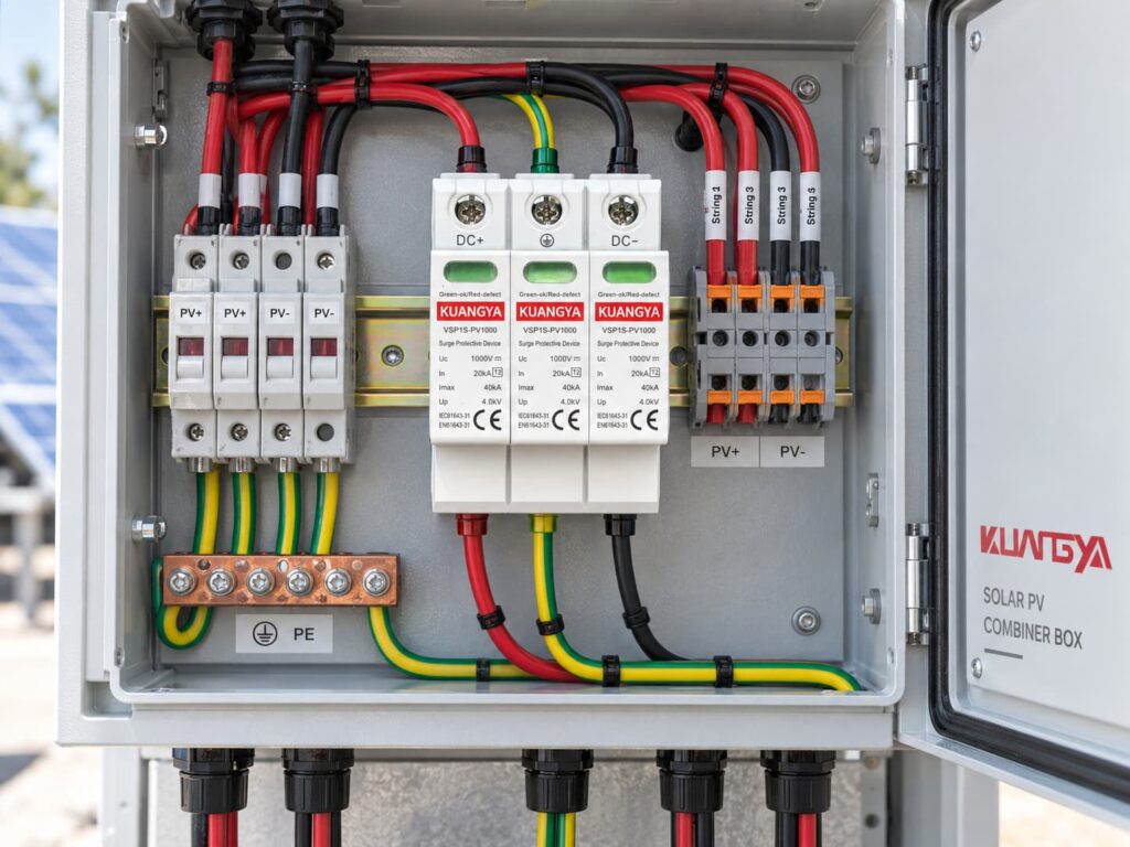
The PV combiner box is one of the most common locations for a DC SPD.
A typical combiner box may include:
The correct SPD configuration depends on the electrical design rather than simply the number of incoming strings.
Например:
Six PV strings entering one combiner box does not mean you need six SPDs.
Similarly:
Two output conductors do not automatically mean the SPD must be 2P.
The SPD protects the electrical node according to its approved circuit arrangement.
Sometimes yes.
If an inverter contains multiple independent MPPT inputs, the surge protection arrangement should be evaluated for each input group.
Factors include:
OBO, for example, publishes PV generator connection boxes designed for one, two and three MPPT configurations, showing that MPPT architecture can directly affect surge-protection layout.
Do not assume so.
Replacement is appropriate only when all of the following are verified:
If the original product uses a Y circuit and the replacement uses a different internal topology, matching the voltage and kA ratings alone is not enough.
The same rule applies.
More modules do not automatically make a product compatible.
A different internal circuit may:
Therefore, substitutions should be based on the electrical specification, not physical appearance.
“The PV string has DC+ and DC−, therefore I need a 2P SPD.”
This is too simplistic.
Check the manufacturer’s approved circuit.
PE is not simply another current-carrying pole.
The manufacturer’s internal SPD architecture determines how it is used.
A three-module device is not automatically safer or stronger.
Two 1000 V SPDs may have completely different:
A large Imax number makes an attractive product label, but it is only one parameter.
Always evaluate In, Up, Iscpv, Ucpv and circuit topology together.
For photovoltaic generator DC-side SPDs, IEC 61643-31 is the key product standard.
IEC 61643-32 addresses selection and application principles for SPDs connected to the DC side of PV systems.
A practical 2P vs 3P DC SPD selection should start with the PV system topology rather than the number of modules.
Do not substitute an AC SPD simply because its voltage looks similar. If you are comparing AC and DC protection devices, read Can an AC SPD Be Used on a DC System? before making a substitution.
Determine maximum cold-weather string Voc.
Then select an SPD with a suitable Ucpv rating.
Determine whether:
Check the inverter manual.
Typical requirements may include:
Verify these in the SPD datasheet.
This depends on the lightning protection concept and installation architecture.
Do not use pole count as a substitute for SPD type.
Never evaluate these values individually.
This is the point where the real answer to 2P vs 3P normally becomes clear.
Check whether the SPD requires:
Follow the SPD manufacturer’s data.
For a more detailed explanation, see our guide to SPD backup fuse and circuit breaker selection.
Keep SPD connecting conductors short.
The distance between the PV array, SPD, and inverter can also affect the overall protection concept. See our detailed guide to SPD distance from the inverter in solar PV systems.
For commercial projects, request:
Before ordering a 2P or 3P PV SPD, send the supplier this information:
| Информация для предоставления | Пример |
|---|---|
| Приложение | Солнечная фотоэлектрическая батарея |
| Maximum DC voltage | 1000 В ПОСТОЯННОГО ТОКА |
| Maximum string Voc | 920 V |
| Система заземления | Floating / isolated |
| Тип УЗИП | Тип 2 |
| Required In | 20 кА |
| Required Imax | 40 кА |
| Установка | Распределительная коробка |
| Remote contact | Required / not required |
| Количество | 500 шт. |
| Target standard | IEC 61643-31 |
A professional supplier should then confirm the suitable circuit rather than simply responding with “2P” or “3P.”
Use this table only as a preliminary guide.
| Ситуация | Что делать |
|---|---|
| Supplier only says “2P 1000 V 40 kA” | Ask for wiring diagram and IEC data |
| Supplier only says “3P is better” | Ask for the protection circuit |
| PV DC side is floating | Use an SPD specifically approved for the floating/isolated topology |
| PV DC side is intentionally grounded | Use the manufacturer’s approved grounded-system configuration |
| System is 1500 V | Verify Ucpv and all 1500 V-specific ratings |
| Inverter already contains SPD | Check whether external SPD is still required based on cable length and protection architecture |
| Множественные входы MPPT | Evaluate each MPPT circuit separately |
| Existing 3-module SPD needs replacement | Match electrical topology, not just physical size |
| PE connection is unclear | Do not install until the manufacturer’s diagram is confirmed |
The following 2P vs 3P DC SPD FAQs address several common questions from PV installers, system designers, and buyers.
It can be, provided the SPD is specifically designed and approved for that PV topology.
The number “2P” alone is not enough information to make the decision.
Because the SPD may use multiple internal protective elements to provide coordinated protection between DC+, DC− and PE.
The physical module count does not necessarily equal the number of active conductors.
Not universally.
Manufacturers use different terminology.
Always check the internal wiring diagram.
Not automatically.
Safety depends on correct circuit design, voltage rating, fault-current capability, disconnection system and correct installation.
Do not do this unless the manufacturer’s instructions explicitly show that connection method.
Unused or incorrectly connected protection elements can change the intended surge protection circuit.
No, unless the manufacturer explicitly rates the product for the actual maximum continuous PV voltage.
A 1000 V Ucpv device is not suitable for a PV system that can exceed its approved continuous voltage.
Не обязательно.
First determine whether the numbers refer to:
Then compare Up, Ucpv, Iscpv and the complete protection circuit.
Не обязательно.
Some inverters contain integrated SPDs.
Whether additional external protection is required depends on:
If your inverter already includes surge protection, see Does a Solar Inverter With a Built-In SPD Still Need an External SPD? for a detailed explanation of when additional protection may still be required.
IEC 61643-31 covers SPDs intended for the DC side of photovoltaic installations up to 1500 V DC.
IEC 61643-32 provides selection and application principles for PV surge protective devices.
The most important point in a 2P vs 3P DC SPD comparison is that the difference is not simply the number of modules.
A photovoltaic SPD must be selected as part of an electrical protection system.
Before choosing a 2P or 3P configuration, confirm:
Real products from OBO, Phoenix Contact, ABB and DEHN show that manufacturers use different terms such as 2-pole, 3-pole, 2+V, two protected lines and Y configuration for PV surge protection.
That is why professional selection should start with the circuit diagram and datasheet—not the number of visible cartridges.
For solar PV projects, the correct question is therefore not:
“Is 2P or 3P better?”
А в том:
“Which SPD circuit is designed for my PV system topology?”
Always follow the latest product datasheet, inverter manufacturer instructions and applicable local electrical regulations when designing or installing surge protection.

