温州市岳陽工業区 325000
勤務時間
月曜日~金曜日:午前7時~午後7時
週末午前10時~午後5時
温州市岳陽工業区 325000
勤務時間
月曜日~金曜日:午前7時~午後7時
週末午前10時~午後5時

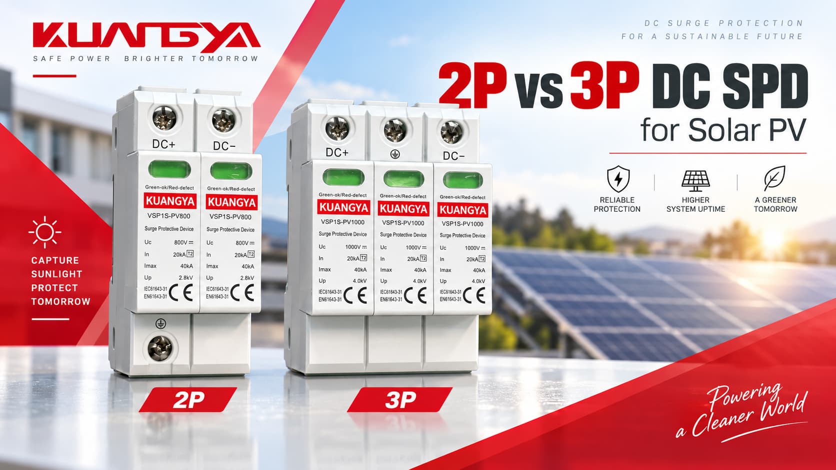
太陽光発電システムにおける2極と3極のDC SPDの選択は、しばしば混乱を招きます。最も一般的な質問の一つは以下の通りです。
2極と3極のどちらのDC SPDを使用すべきでしょうか?
一見すると、答えは単純に思えます。PVストリングにはDCプラスとDCマイナスの導体があるため、2極のSPDで十分に見えるかもしれません。では、なぜ多くの太陽光発電用サージ保護デバイスが3つの保護モジュールや3極構成を採用しているのでしょうか?
その理由は以下の通りです。 2極および3極という表記は、メーカーによって必ずしも同じ内部保護回路を指すとは限りません。.
正しい選択は以下に依存します。
本ガイドでは、2Pおよび3P DC SPDの違いを解説し、実際のメーカー事例を紹介するとともに、太陽光発電システムにおける実用的な選定方法を提供します。.
A PV回路に2本の活線があるからといって、2P DC SPDが自動的に適合するわけではありません。, そして 3P DC SPDはモジュールが1つ多いため、自動的に優れているというわけではありません。.
正しいSPDは、電気的トポロジーおよびメーカーが承認した接続回路に従って選択する必要があります。.
| 質問 | 短い回答 |
|---|---|
| PVストリングには2本の活線がありますか? | 通常はあります:DC+およびDC- |
| それは常に2P SPDが必要であることを意味しますか? | いいえ |
| 3P SPDの3番目のモジュールは、単なる「PE極」ですか? | 必ずしもそうとは限りません |
| 3P SPDは2P SPDよりも強力ですか? | 本質的にそうとは限りません |
| 2P SPDと3P SPDは互換性がありますか? | メーカーがその回路での使用を明示的に許可している場合に限ります |
| 最も重要なことは何ですか? | 保護モード、システム接地、Ucpv、Iscpv、および承認された配線 |
| PV用DC SPDを規定する規格は何ですか? | IEC 61643-31 |
| PV用SPDの選定と適用を規定する規格は何ですか? | IEC 61643-32 |
最も安全な原則は以下の通りです:
モジュール数だけでPV用SPDを選定しないでください。メーカーの回路図を確認し、そのSPDが自身のPVシステム構成に対して承認されていることを確認してください。.
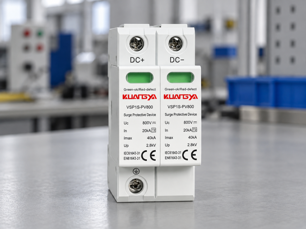
一般的な電気用語において、「P」は通常以下を意味します。 極(ポール).
しかし、PV用SPDの用語は、遮断器(ブレーカー)の用語ほど単純ではありません。.
メーカーによって、製品説明には以下の用語が使用される場合があります:
これらの用語は関連していますが、それぞれ異なります 常に互換性があるとは限らない.
例えば、あるメーカーはデバイスを次のように説明するかもしれない 2極PV用SPD, 、一方で同じDC+およびDC-導体を保護する別の製品には、物理的に 3つの交換可能な保護素子が含まれている場合があります.
これが、購入者がPV用SPDを外観だけで比較すべきではない主な理由の1つです。.
これら3つの概念は区別されるべきです。.
| 期間 | 何を説明しているか | なぜ重要なのか |
|---|---|---|
| 保護導体 | 保護対象の電気導体 | 通常、PVストリングにおけるDC+およびDC- |
| 極/モジュール | 物理的または電気的なSPD素子 | メーカー固有の用語 |
| 保護モード | サージ電圧が制限される経路 | SPDが対応可能なサージ条件を決定するもの |
| PE接続 | 保護接地への接続 | サージ放電の基準/経路を提供 |
| Y結線 | Y構成で配置された内部保護回路 | 太陽光発電用SPDで一般的 |
| ベース位置 | DINレールモジュールの物理的な配置位置 | 保護導体の数と必ずしも一致しません |
ということだ:
2つの保護DC導体に対して、必ずしも2つの物理的なSPDカートリッジが必要とは限りません。.
同じ原則はAC側にも当てはまります。モジュール数だけで内部回路が定義されるわけではありません。詳細は以下を参照してください。 3+1方式と4+0方式のSPD比較.
太陽光発電アレイは、通常の230/400V AC配電盤には存在しないいくつかの特殊な条件を生み出します。.
PV用SPDは以下の条件下で動作する必要があります:
AC電流とは異なり、DC電流は半サイクルごとに自然にゼロを通過することはありません。.
そのため、DC側においては故障時の遮断およびSPDの内部設計が特に重要となります。.
IEC 61643-31 太陽光発電設備のDC側を対象としたSPDを具体的に規定しています。 DC1500V.
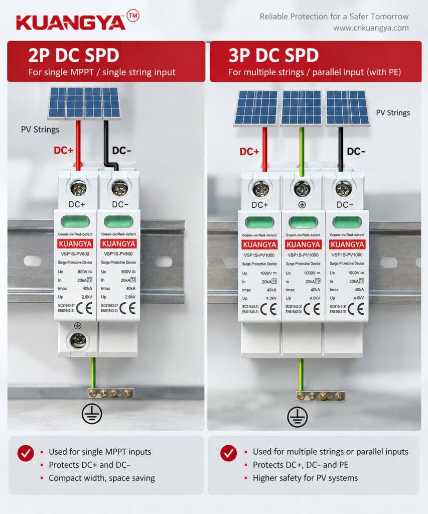
太陽光発電用SPDは、複数の点間での電圧を制限する必要がある場合があります。.
一般的な保護モードは以下の通りです。
| 保護モード | 説明 |
|---|---|
| DC+ → PE | 正極導体と接地間のサージ |
| DC− → PE | Surge between negative conductor and earth |
| DC+ → DC− | Differential surge between the two DC conductors |
A correctly designed PV SPD can provide several of these protection paths through its internal network.
This is why looking only at the number of visible modules can be misleading.
For example, Phoenix Contact publishes PV SPDs using a Y configuration that provide protection modes between:
even though the manufacturer’s naming may refer to a “2+V” arrangement. Phoenix Contact lists these modes explicitly for its 1000 V PV devices.
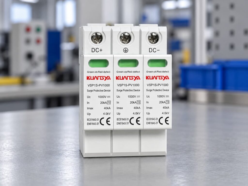
A Y-circuit is a common protective arrangement used in photovoltaic surge protection.
Instead of simply placing one MOV from positive to earth and another MOV from negative to earth, the SPD uses a coordinated internal network.
Conceptually:
DC+
↓
保護要素
↓
Common protection point
↓
保護要素
↓
PE
and another path connects the DC− conductor into the protective network.
The exact circuit varies by manufacturer.
The important point is that the internal network can provide protection for both:
while also addressing PV-specific fault conditions.
OBO, for example, describes its 1000 V PV surge protection solution as using an error-resistant Y circuit.
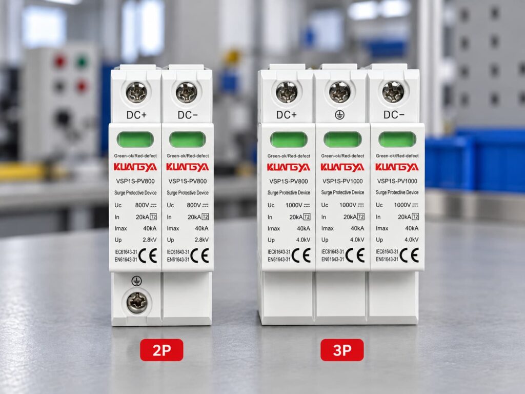
The following table provides a useful engineering comparison, but the manufacturer’s wiring diagram always takes priority.
| 特徴 | 2P DC SPD | 3P / Three-Module DC SPD |
|---|---|---|
| Physical size | Often smaller | Usually wider |
| Number of visible modules | Often 2 | Often 3 |
| DC conductors protected | Typically DC+ and DC− | Typically DC+ and DC− |
| PE接続 | May be included | Usually included |
| Internal circuit | Depends on manufacturer | Often PV-specific Y circuit |
| Suitable for floating PV | Model-dependent | Common, but still model-dependent |
| Suitable for grounded PV | Model-dependent | Model-dependent |
| Differential protection | Check datasheet | Check datasheet |
| Common-mode protection | Check datasheet | Common on PV-specific designs |
| コスト | Often lower | Often slightly higher |
| DIN rail width | 通常はもっと小さい | Usually larger |
| Better protection? | 自動的ではありません | 自動的ではありません |
The key difference is therefore not simply “two modules versus three modules.”
The real difference is the approved protection circuit behind those modules.
OBO publishes a V20 1000 V DC photovoltaic surge protective device described as:
V20-C 2-PH-1000
The manufacturer identifies it as:
2-pole for earthed PV systems.
Published specifications include approximately:
| 仕様 | OBO V20-C 2-PH-1000 |
|---|---|
| 申し込み | Earthed PV systems |
| Pole version | 2 |
| Maximum continuous DC voltage | DC1000V |
| タイプ | タイプ2 |
| Nominal discharge current In | 20 kA |
| Maximum discharge current Imax | 40 kA |
| Voltage protection level Up | ≤4.0 kV |
| インストール | 35 mm DINレール |
This is a good example of why the phrase “2P DC SPD” requires context.
OBO specifically associates this configuration with earthed photovoltaic systems rather than presenting it as a universal solution for every PV system.
OBO also offers:
This product is described as:
3-pole for PV systems.
Its published data includes:
| 仕様 | OBO V20-C 3-PH-1000 |
|---|---|
| Pole version | 3 |
| Maximum continuous voltage | DC1000V |
| タイプ | タイプ2 |
| Nominal discharge current In | 20 kA |
| Maximum discharge current Imax | 40 kA |
| Voltage protection level Up | ≤4.0 kV |
| Circuit | PV Y circuit |
| インストール | 35 mm DINレール |
OBO also describes this product family as using an error-resistant Y circuit for PV applications.
Notice something important:
The 2-pole and 3-pole products can have very similar headline ratings:
Yet their intended system configurations are different.
This demonstrates why voltage and kA values alone are not enough to select an SPD.
Phoenix Contact’s VAL-MS 1000DC-PV/2+V-FM provides another useful example.
Its VALVETRAB PV devices use a Y configuration and provide protection modes including:
One published Type 2 model for a 1000 V DC PV system has:
| パラメータ | Published Value |
|---|---|
| Ucpv | DC1000V |
| Iscpv | 2000 A |
| で | 20 kA |
| アイマックス | 40 kA |
| 上へ | ≤3.3 kV |
| Circuit | Y configuration |
| 保護モード | L+/L−, L+/PE, L−/PE |
Phoenix Contact describes this product as being suitable for a two-position isolated 1000 V DC system, yet the internal circuit still provides three protection relationships.
Again, this proves that:
Number of active PV conductors ≠ number of internal surge protection elements.
ABB provides perhaps the clearest example of why terminology can confuse buyers.
ABB’s OVR PV Type 2 series specifies:
Protected lines: 2
but the protection modes include:
ABB lists PV models for both:
For its 1000 V Type 2 product, published characteristics include:
| パラメータ | ABB OVR PV T2 40-1000 |
|---|---|
| Protected lines | 2 |
| Ucpv | DC1000V |
| アイマックス | 40 kA |
| で | 20 kA |
| 上へ | 4 kV |
| Iscpv | 10 kA |
| 保護モード | DC+/DC−, DC+/G, DC−/G |
For its 1500 V version:
| パラメータ | ABB OVR PV T2 40-1500 |
|---|---|
| Protected lines | 2 |
| Ucpv | DC1500V |
| アイマックス | 40 kA |
| で | 15 kA |
| 上へ | 5 kV |
| Iscpv | 10 kA |
ABB’s data demonstrates an important distinction:
“Protected lines: 2” does not mean the SPD only provides two possible surge paths.
DEHN also publishes a 1000 V photovoltaic Type 2 SPD described as a:
two-pole surge arrester
for protecting one MPP input.
One DEHNcube YPV SCI 1000 model has published characteristics including:
| パラメータ | Published Value |
|---|---|
| 申し込み | One MPP input |
| SPDタイプ | タイプ2 |
| Ucpv | 1000 V |
| Iscpv | 1 kA |
| で | 12.5 kA |
| アイマックス | 25 kA |
| 上へ | ≤4 kV |
| 保護等級 | IP65 |
DEHN also emphasizes a PV-specific Y circuit and its DC disconnection technology.
The lesson is again the same:
“2-pole” alone does not tell you whether the device matches your PV architecture.
| Manufacturer Example | Manufacturer Terminology | PV Voltage | Key Point |
|---|---|---|---|
| OBO V20-C 2-PH-1000 | 2極 | 1000 V | Specified for earthed PV systems |
| OBO V20-C 3-PH-1000 | 3極 | 1000 V | PV Y-circuit design |
| Phoenix Contact VALVETRAB | 2+V / Y configuration | 1000 V | Protects L+/L− and both lines to PE |
| ABB OVR PV | 2 protected lines | 1000/1500 V | Multiple protection modes despite two protected conductors |
| DEHNcube YPV SCI | 2極 | 1000 V | PV-specific design for one MPP input |
This is why professional SPD selection should be based on the manufacturer’s protection circuit, not only a marketplace listing that says “2P” or “3P.”
This is one of the most common questions.
結論から言うと:
必ずしもそうではない。.
PE means protective earth.
In a PV SPD, PE may be connected to one or more internal surge protection components, but the PE terminal is not always counted as an additional “pole” in the product name.
Manufacturer terminology varies.
例えば、こうだ:
したがって:
Never assume that a “3P SPD” means “DC+, DC− and PE are three equivalent poles.”
They are not equivalent conductors.
Not automatically.
A three-module product can be highly suitable for one PV topology and incorrect for another.
Likewise, a two-pole product specifically designed for a particular grounded system may be exactly what the manufacturer requires.
A better comparison is:
| Bad Selection Question | Better Selection Question |
|---|---|
| Which has more poles? | Which topology is approved for my PV system? |
| Which has more modules? | Which protection modes are provided? |
| Which has the larger kA number? | Are In, Imax/Iimp and Up suitable for the application? |
| Which one is cheaper? | Does it comply with the required PV SPD standard? |
| Is 3P stronger? | Is the device designed for my earthing arrangement? |
The internal circuit matters more than the number printed after “P.”
Before choosing between different SPD arrangements, determine how the PV DC side is referenced to earth.
Two broad situations may occur.
Neither DC+ nor DC− is intentionally bonded directly to PE under normal operating conditions.
This arrangement is common in many modern PV inverter systems.
The SPD must be suitable for the insulation and monitoring concept of the inverter and PV generator.
One part of the DC system is intentionally referenced to earth according to the system design.
A manufacturer may provide a specific SPD arrangement for this configuration.
For example, OBO explicitly markets its 2-pole 1000 V model for earthed PV systems.
This is why installers should never convert between configurations simply to reduce the number of SPD modules.
Another common misunderstanding is mixing up:
pole configuration
with:
Type 1, Type 1+2 or Type 2.
They describe different characteristics.
| 期間 | 意味 |
|---|---|
| 2P / 3P | Pole or module arrangement |
| タイプ1 | Lightning-current-capable SPD test category |
| タイプ2 | Surge protection tested with 8/20 µs current waveform |
| タイプ1+2 | Combined lightning-current and surge protection functionality |
| Ucpv | Maximum continuous PV operating voltage |
| で | 公称放電電流 |
| アイマックス | 最大放電電流 |
| インプ | Impulse discharge current |
| 上へ | 電圧保護レベル |
| Iscpv | PV short-circuit current rating |
A 3P Type 2 SPD および 3P Type 1+2 SPD are therefore not the same device.
Likewise, a 2P Type 2 cannot be replaced with a 3P Type 1+2 simply because the second product appears “bigger.”
そうだ。.
The PV voltage does affect SPD selection, but it does not by itself determine pole arrangement.
For example, PV SPDs are available for:
The key voltage parameter is normally Ucpv, the maximum continuous operating voltage of the PV SPD.
For a detailed method of selecting 600V, 1000V, or 1500V protection, see our DC SPD voltage selection guide for solar PV systems.
Ucpv must be suitable for the maximum voltage that can appear in the PV array.
PV module open-circuit voltage rises when cell temperature falls.
Therefore, the system’s maximum possible string voltage may be higher than the simple STC Voc calculation.
A simplified selection process is:
Maximum string voltage ≈ number of modules in series × module Voc × low-temperature correction factor
The exact correction should follow:
The selected SPD must have a Ucpv rating appropriate for the resulting maximum PV voltage.
Consider a commercial PV installation with:
Approximate maximum string voltage:
18 × 49 × 1.12 = 987.8 V
A 600 V SPD would clearly be unsuitable.
The designer would need a PV SPD whose Ucpv safely accommodates the calculated voltage according to the manufacturer’s selection rules.
But after establishing the voltage requirement, the designer must still determine:
Only then should pole configuration be selected.
Imagine two products listed online:
At first glance, Product B may appear “better.”
But that conclusion is impossible without knowing:
| Required Information | Product A | Product B |
|---|---|---|
| Ucpv | ? | ? |
| で | ? | ? |
| アイマックス | 40 kA | 40 kA |
| インプ | ? | ? |
| 上へ | ? | ? |
| Iscpv | ? | ? |
| Circuit topology | ? | ? |
| Grounded/floating system approval | ? | ? |
| IEC 61643-31 | ? | ? |
| Internal disconnection | ? | ? |
If these values are missing, the pole count provides very little useful information.
For PV SPD procurement, we recommend checking parameters in approximately this order:
| Priority | パラメータ | なぜ重要なのか |
|---|---|---|
| 1 | 申し込み | Must be designed for PV DC |
| 2 | Ucpv | Must withstand continuous PV voltage |
| 3 | System topology | Grounded/floating arrangement |
| 4 | 保護モード | Confirms actual surge paths |
| 5 | タイプ | Type 1, Type 1+2 or Type 2 |
| 6 | 上へ | Determines clamping/protection level |
| 7 | で | Normal surge discharge capability |
| 8 | Imax / Iimp | Surge or lightning-current capability |
| 9 | Iscpv | PV short-circuit withstand/failure capability |
| 10 | Disconnection system | Important for safe end-of-life behavior |
| 11 | Backup protection | Must match manufacturer requirements |
| 12 | Pole/module arrangement | Select only after topology is confirmed |
If you are not familiar with these ratings, our guide to DC SPD specifications such as Ucpv, In, Imax, Up and Iscpv explains what each value means and how they differ.
This order avoids one of the most common purchasing mistakes: choosing an SPD by voltage, kA and pole count while ignoring the internal circuit.
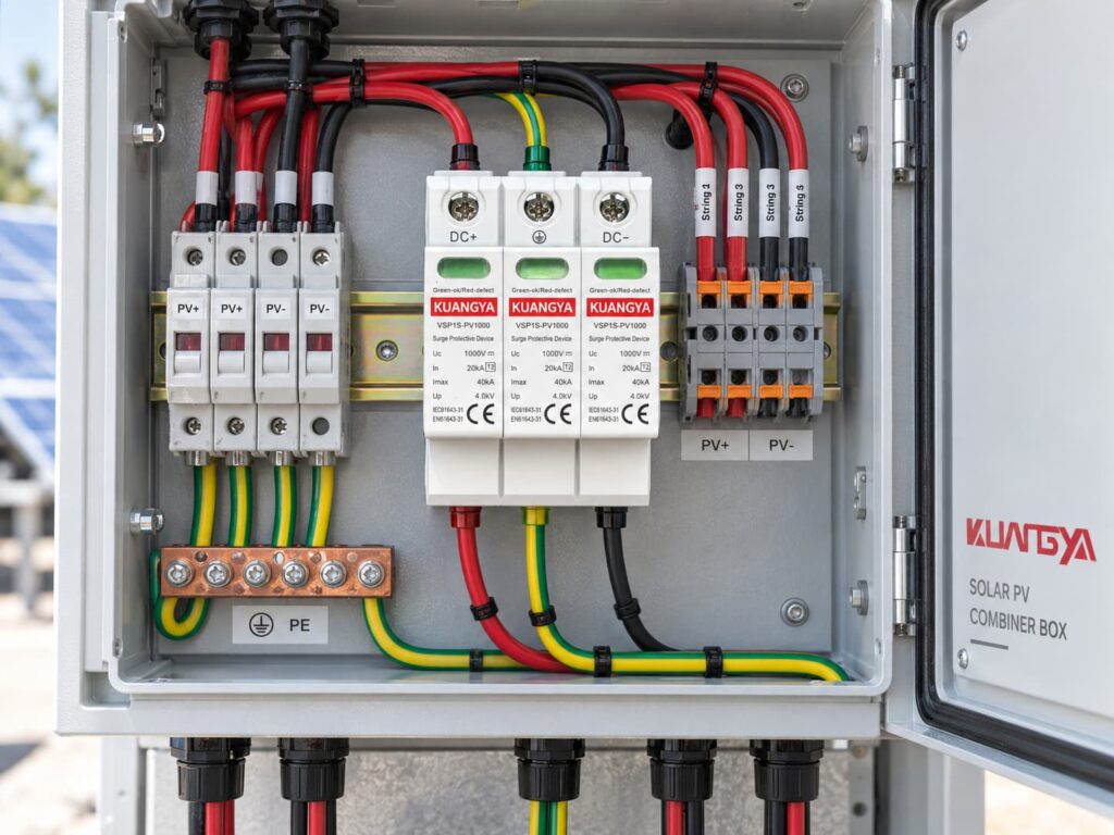
The PV combiner box is one of the most common locations for a DC SPD.
A typical combiner box may include:
The correct SPD configuration depends on the electrical design rather than simply the number of incoming strings.
例えば、こうだ:
Six PV strings entering one combiner box does not mean you need six SPDs.
Similarly:
Two output conductors do not automatically mean the SPD must be 2P.
The SPD protects the electrical node according to its approved circuit arrangement.
Sometimes yes.
If an inverter contains multiple independent MPPT inputs, the surge protection arrangement should be evaluated for each input group.
Factors include:
OBO, for example, publishes PV generator connection boxes designed for one, two and three MPPT configurations, showing that MPPT architecture can directly affect surge-protection layout.
Do not assume so.
Replacement is appropriate only when all of the following are verified:
If the original product uses a Y circuit and the replacement uses a different internal topology, matching the voltage and kA ratings alone is not enough.
The same rule applies.
More modules do not automatically make a product compatible.
A different internal circuit may:
Therefore, substitutions should be based on the electrical specification, not physical appearance.
“The PV string has DC+ and DC−, therefore I need a 2P SPD.”
This is too simplistic.
Check the manufacturer’s approved circuit.
PE is not simply another current-carrying pole.
The manufacturer’s internal SPD architecture determines how it is used.
A three-module device is not automatically safer or stronger.
Two 1000 V SPDs may have completely different:
A large アイマックス number makes an attractive product label, but it is only one parameter.
Always evaluate In, Up, Iscpv, Ucpv and circuit topology together.
For photovoltaic generator DC-side SPDs, IEC 61643-31 is the key product standard.
IEC 61643-32 addresses selection and application principles for SPDs connected to the DC side of PV systems.
A practical 2P vs 3P DC SPD selection should start with the PV system topology rather than the number of modules.
Do not substitute an AC SPD simply because its voltage looks similar. If you are comparing AC and DC protection devices, read Can an AC SPD Be Used on a DC System? before making a substitution.
Determine maximum cold-weather string Voc.
Then select an SPD with a suitable Ucpv rating.
Determine whether:
Check the inverter manual.
Typical requirements may include:
Verify these in the SPD datasheet.
This depends on the lightning protection concept and installation architecture.
Do not use pole count as a substitute for SPD type.
Never evaluate these values individually.
This is the point where the real answer to 2P vs 3P normally becomes clear.
Check whether the SPD requires:
Follow the SPD manufacturer’s data.
For a more detailed explanation, see our guide to SPD backup fuse and circuit breaker selection.
Keep SPD connecting conductors short.
The distance between the PV array, SPD, and inverter can also affect the overall protection concept. See our detailed guide to SPD distance from the inverter in solar PV systems.
For commercial projects, request:
Before ordering a 2P or 3P PV SPD, send the supplier this information:
| 提供すべき情報 | 例 |
|---|---|
| 申し込み | 太陽光発電 |
| Maximum DC voltage | DC1000V |
| Maximum string Voc | 920 V |
| 接地構成 | Floating / isolated |
| SPDタイプ | タイプ2 |
| Required In | 20 kA |
| Required Imax | 40 kA |
| インストール | PVコンバイナーボックス |
| Remote contact | Required / not required |
| 数量 | 500個 |
| Target standard | IEC 61643-31 |
A professional supplier should then confirm the suitable circuit rather than simply responding with “2P” or “3P.”
Use this table only as a preliminary guide.
| 状況 | 何をすべきか |
|---|---|
| Supplier only says “2P 1000 V 40 kA” | Ask for wiring diagram and IEC data |
| Supplier only says “3P is better” | Ask for the protection circuit |
| PV DC side is floating | Use an SPD specifically approved for the floating/isolated topology |
| PV DC side is intentionally grounded | Use the manufacturer’s approved grounded-system configuration |
| System is 1500 V | Verify Ucpv and all 1500 V-specific ratings |
| Inverter already contains SPD | Check whether external SPD is still required based on cable length and protection architecture |
| 複数のMPPT入力 | Evaluate each MPPT circuit separately |
| Existing 3-module SPD needs replacement | Match electrical topology, not just physical size |
| PE connection is unclear | Do not install until the manufacturer’s diagram is confirmed |
The following 2P vs 3P DC SPD FAQs address several common questions from PV installers, system designers, and buyers.
It can be, provided the SPD is specifically designed and approved for that PV topology.
The number “2P” alone is not enough information to make the decision.
Because the SPD may use multiple internal protective elements to provide coordinated protection between DC+, DC− and PE.
The physical module count does not necessarily equal the number of active conductors.
Not universally.
Manufacturers use different terminology.
Always check the internal wiring diagram.
Not automatically.
Safety depends on correct circuit design, voltage rating, fault-current capability, disconnection system and correct installation.
Do not do this unless the manufacturer’s instructions explicitly show that connection method.
Unused or incorrectly connected protection elements can change the intended surge protection circuit.
No, unless the manufacturer explicitly rates the product for the actual maximum continuous PV voltage.
A 1000 V Ucpv device is not suitable for a PV system that can exceed its approved continuous voltage.
必ずしもそうではない。.
First determine whether the numbers refer to:
Then compare Up, Ucpv, Iscpv and the complete protection circuit.
必ずしもそうではない。.
Some inverters contain integrated SPDs.
Whether additional external protection is required depends on:
If your inverter already includes surge protection, see Does a Solar Inverter With a Built-In SPD Still Need an External SPD? for a detailed explanation of when additional protection may still be required.
IEC 61643-31 covers SPDs intended for the DC side of photovoltaic installations up to 1500 V DC.
IEC 61643-32 provides selection and application principles for PV surge protective devices.
The most important point in a 2P vs 3P DC SPD comparison is that the difference is not simply the number of modules.
A photovoltaic SPD must be selected as part of an electrical protection system.
Before choosing a 2P or 3P configuration, confirm:
Real products from OBO, Phoenix Contact, ABB and DEHN show that manufacturers use different terms such as 2-pole, 3-pole, 2+V, two protected lines and Y configuration for PV surge protection.
That is why professional selection should start with the circuit diagram and datasheet—not the number of visible cartridges.
For solar PV projects, the correct question is therefore not:
“Is 2P or 3P better?”
正しくは次の通りです。
“Which SPD circuit is designed for my PV system topology?”
Always follow the latest product datasheet, inverter manufacturer instructions and applicable local electrical regulations when designing or installing surge protection.

