温州市岳陽工業区 325000
勤務時間
月曜日~金曜日:午前7時~午後7時
週末午前10時~午後5時
温州市岳陽工業区 325000
勤務時間
月曜日~金曜日:午前7時~午後7時
週末午前10時~午後5時

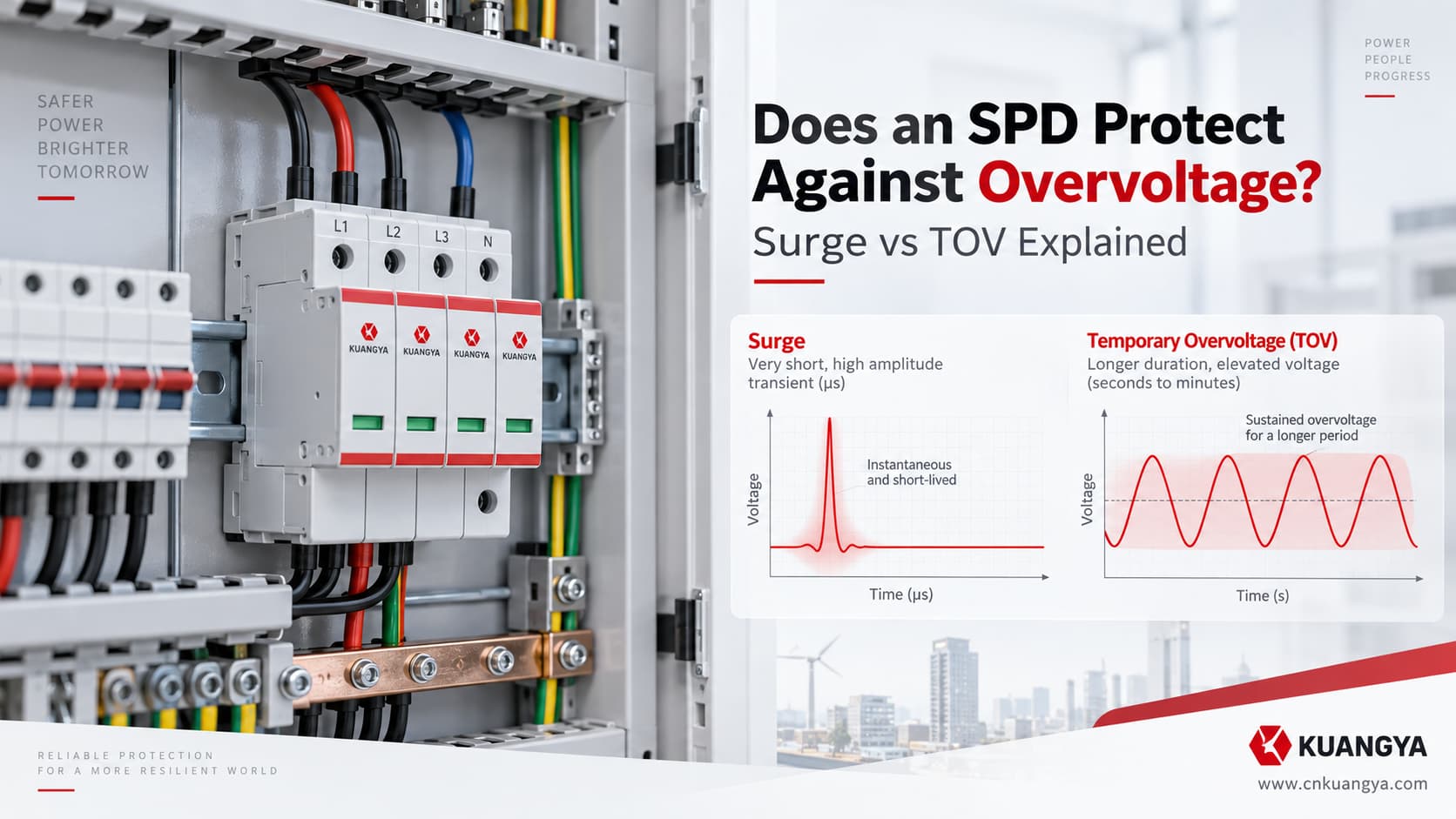
SPDは過電圧から保護しますか? はい、ただしその答えはどのような種類の過電圧が関与しているかによって異なります。サージ防護デバイス(SPD)は主に過渡過電圧を制限するように設計されていますが、一時的過電圧(TOV)や持続的な異常電圧については別の分析が必要です。.
「過電圧保護」というフレーズは、 “「過電圧保護」” すべての過電圧が過渡サージであるとは限らないため、誤解を招く可能性があります。.
次の3つの状況を検討してください:
雷サージは、わずか数秒の極めて短い時間だけ配電盤に到達します。.
ネットワークの故障により、供給電圧が数秒間にわたって大幅に上昇します。.
あるいは、中性線の接触不良により、故障が修理されるまで設備の一部に異常電圧が残留することがあります。.
これら3つはすべて 過電圧, 、関連していますが、同一の電気的事象ではありません。.
また、SPDはこれらすべてに対して同じように反応するわけではありません。.
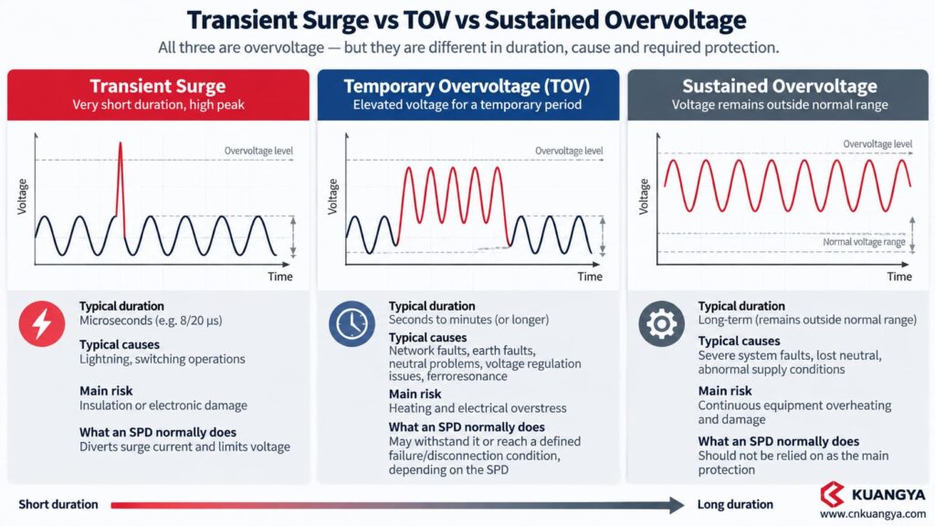
最も重要な違いは以下の通りです。
従来のSPDは、主に過渡過電圧を制限するように設計されています。一時的または持続的な異常供給電圧に対する保護として、自動的に見なすべきではありません。.
この区別は、SPDの選定、故障解析、さらには技術者が損傷したSPDをどのように解釈するかに影響を与えます。.
IEC 61643-01:2024 は、低圧SPDを少なくとも1つの非線形素子を含み、かつ以下の目的を持つ機器と定義しています。 サージ電圧を制限し、サージ電流を分流させること. 。交流低圧電源システムの場合、製品要件は以下に規定されています。 IEC 61643-11:2025.
はい。ただし、特定の種類の過電圧に限ります。.
SPDは主に以下の目的で設計されています。 過渡過電圧, 、雷サージや開閉サージなどによって引き起こされるもの。.
通常、供給電圧を調整したり、RMS電圧が高すぎる場合に負荷を遮断したりすることを目的としたものではありません。.
下表に基本的な違いを示します。.
| 電気的状態 | 代表的な特性 | 主なリスク | SPDの一般的な機能 |
|---|---|---|---|
| 過渡サージ | 極めて短いインパルス | 絶縁破壊/電子機器の損傷 | サージ電流を分流し、電圧を制限する |
| 一時的過電圧(TOV) | 一時的な期間における商用周波数電圧の上昇 | 発熱および電気的過負荷 | SPDの仕様に応じて、耐え得る場合もあれば、規定の故障/遮断状態に至る場合もある |
| 持続的な異常電圧 | 電源が正常動作範囲外の状態が継続している | 機器の継続的な過熱および損傷 | 主保護として依存すべきではない |
| 不足電圧 | 電源電圧が正常範囲を下回っている | モーターまたは機器の誤動作 | 従来のSPDでは修正できない |
| 過電流/短絡 | 過負荷または故障電流 | 導体/機器の過熱 | ヒューズまたは回路遮断器がこの機能を果たします |
これが、以下の問いが生じる理由です:
“「私の分電盤にはすでにSPDが設置されていますか?」”
これは、以下の問いとは異なります:
“「私の機器はあらゆる異常電圧状態に対して保護されていますか?」”
そうではありません。.
「クラス」という言葉 過電圧 は広範なカテゴリーです。.
どの保護デバイスが応答すべきかを決定する前に、事象の持続時間と原因を理解することが不可欠です。.
過渡過電圧とは、短時間の電圧外乱のことです。.
一般的な原因は以下の通りである。
標準的なSPD試験では、一般的に以下のようなインパルス波形が使用されます。 8/20 μs電流波形 タイプ2アプリケーション用。.
この現象は極めて短時間で発生します。.
これこそが、SPDが設計された環境そのものです。クランプおよび電流分流プロセスの詳細については、以下のガイドをご覧ください。 DCサージ保護デバイスの仕組み.
TOV(一時的過電圧)は異なります。.
電圧はインパルスよりもはるかに長く上昇した状態が続き、一般的にマイクロ秒単位の単一サージではなく、電力系統に関連しています。.
考えられる原因は以下の通りです:
大きさだけでリスクを定義することはできない。.
電圧 + 持続時間 + 保護モード + 接地システム + SPD設計 すべてが重要である。.
例えばABBは、 ウク, 最大連続使用電圧と、 UT, 一時過電圧耐力を区別している。その OVR実務ガイド TOV(一時的過電圧)の挙動をサージ電流性能とは分けて扱い、適用されるストレスがSPDの接続方法やネットワーク構成に依存することを示しています。.
異常な供給電圧が一時的な障害イベントのように振る舞うのではなく継続する場合、技術的な課題は再び変化します。.
一般的な並列接続型SPDを電圧調整器として使用してはなりません。.
設計目的が以下の場合、通常、RMS電圧を監視し遮断を開始するように設計されたデバイスが必要です。
供給電圧が許容閾値を超過または下回った状態が続く場合に負荷を遮断する。.
例えば、シュナイダーエレクトリック Harmony 電圧監視リレー 過電圧および不足電圧の監視機能を提供します。これは、SPDの高速サージ放電機能とは異なる機能です。.
This seems contradictory at first.
An SPD may discharge a very large surge current measured in kiloamperes.
This is why asking “does an SPD protect against overvoltage?” requires first identifying whether the event is a transient surge, a TOV, or a sustained abnormal supply condition.
So why could a much smaller abnormal AC voltage damage it?
回答は以下の通りです。
Energy is not determined by current magnitude alone. Time matters.
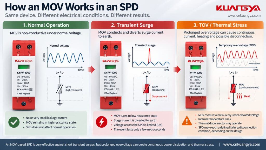
Consider an MOV-based SPD.
Under normal operating voltage, the MOV remains in a high-impedance state and conducts only a very small current.
When a transient surge raises the voltage sufficiently, the MOV becomes conductive.
Surge current is diverted through the SPD and the voltage is limited.
The surge then disappears very quickly.
The MOV returns toward its normal high-impedance state.
A simplified sequence looks like this:
| ステージ | Voltage condition | MOV behavior |
|---|---|---|
| Normal operation | Below its conduction region | High impedance |
| Surge arrives | Voltage rises rapidly | MOV becomes conductive |
| Surge current flows | Very short high-energy event | Energy is absorbed/diverted |
| Surge ends | Voltage returns to normal | MOV returns toward standby |
| TOV persists | Voltage remains abnormally high | Continued conduction may produce heat |
| Excessive thermal stress | Temperature continues increasing | Thermal disconnector may operate or MOV may be damaged |
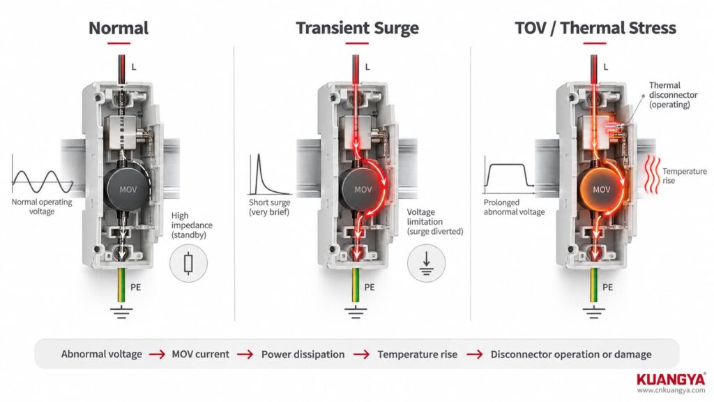
That last condition is the problem.
If the voltage does not disappear quickly enough, the MOV may continue conducting.
Electrical energy then becomes heat.
In simplified form:
abnormal voltage → MOV current → power dissipation → temperature rise → disconnector operation or component damage
This is why:
40 kA Imax does not mean that an SPD can withstand any abnormal supply voltage.
Imax describes a defined surge-current capability.
TOV behavior describes a completely different type of electrical stress.
Another common source of confusion is mixing voltage specifications together.
Suppose an SPD datasheet contains ウク, 上へ and a TOV/UT specification.
They should not be compared as though they describe the same thing.
| パラメータ | Main question it answers | What it does NOT tell you |
|---|---|---|
| Uc / MCOV | What voltage can remain continuously across the SPD under specified conditions? | Surge protection level |
| 上へ | How much voltage appears at the SPD during standardized surge testing? | Maximum continuous voltage |
| UT / TOV behavior | How does the SPD behave during a specified temporary abnormal voltage condition? | Universal protection against every overvoltage |
| で | What nominal surge current is used for the relevant discharge-current test? | TOV withstand |
| アイマックス | What maximum discharge current is declared for the relevant Type 2 test? | Ability to survive neutral loss |
| インプ | What impulse-current duty is declared for Type 1 applications? | Sustained-overvoltage protection |
The IEC definition of an SPD focuses on limiting surge voltage and diverting surge current. IEC 61643-12:2020 separately covers selection, operation, location and coordination principles for AC power SPDs. If the differences between Uc, Up, In, Imax and Iscpv are not yet clear, see our DC SPD仕様ガイドをご参照ください.
Not automatically.
It is tempting to think:
Higher Uc = safer SPD.
それはあまりに単純すぎます。.
A suitably higher Uc can give more operating-voltage margin, but SPD selection involves a tradeoff.
The device must remain stable at the expected continuous system voltage while still providing an appropriate surge protection level.
NIST researchers have described this design dilemma for decades: an SPD must provide effective surge limitation without being expected to clamp longer-duration power-frequency overvoltages indefinitely.
したがって:
Do not deliberately oversize Uc simply because you are worried about TOV.
Instead, check:
| 質問 | なぜそれが重要なのか |
|---|---|
| What is the nominal system voltage? | Establishes basic operating condition |
| What is the maximum expected continuous voltage? | Determines Uc compatibility |
| What is the earthing system? | Influences voltage appearing across protection modes |
| Which protection modes are used? | L-N and L-PE may see different stresses |
| What TOV behavior does the manufacturer declare? | Determines behavior under specified fault conditions |
| What Up is required? | Determines surge-voltage limitation |
| What does the protected equipment tolerate? | Required for insulation coordination |
This is where the distinction stops being theoretical.
A NIST-hosted paper by François Martzloff and Arshad Mansoor discusses actual power-system overvoltage scenarios.
One example cited from an EPRI report involved a power-system switching incident during restoration of power phase by phase.
The recorded condition produced an RMS voltage exceeding 150% of normal voltage for approximately four seconds.
The researchers identified the phenomenon as a temporary overvoltage associated with ferroresonance.
Notice what makes this different from a normal SPD surge event:
| Lightning/switching impulse | Documented TOV case |
|---|---|
| Extremely short | About 4 seconds |
| Typically discussed with impulse waveforms | Power-frequency RMS voltage remained elevated |
| SPD diverts impulse energy | SPD may remain electrically stressed for much longer |
| Surge current rating is important | TOV behavior and continuous-voltage margin become critical |
Four seconds may sound short to a person.
For an MOV that is dissipating abnormal power continuously, it is extremely long compared with a microsecond-scale surge.
Another NIST-hosted TOV study by researchers from Eaton Electrical, EPRI Solutions and François Martzloff investigated what happens when commercial SPDs experience several TOV conditions.
The study intentionally exposed commercial devices to conditions representing real power-system abnormalities.
The test program included the following examples:
| Simulated condition | Applied stress |
|---|---|
| Poor voltage regulation | 1.15 pu / 138 V for 6 hours |
| Power-system fault | 1.3 pu / 156 V for 2 seconds |
| Loss of secondary neutral | 1.5 pu / 180 V for 4 hours |
| Ferroresonance | 2.0 pu / 240 V for 1 minute |
| High-voltage conductor contact with LV system | 3.0 pu / 360 V for 1 second |
The values relate to the study’s 120 V system basis; they must ない be copied directly as ratings for another SPD or another electrical system.
The result was especially important.
The researchers found that SPD response varied substantially depending on the product design.
The three cord-connected SPD specimens failed under the simulated 1.5 pu neutral-loss condition, while the two permanently connected specimens used in that study survived the first four test scenarios. Under the extreme 3.0 pu test, the permanently connected specimens experienced partial internal failure but retained some protective capability.
This should ない be interpreted as:
“Hardwired SPDs always survive TOV.”
The study used only a small group of specific products and represents historical designs.
Its real lesson is more useful:
Two products with similar-looking surge ratings may behave very differently under a long-duration abnormal voltage condition.
That is why TOV cannot be judged from Imax alone.
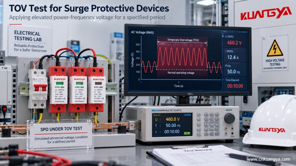
Neutral interruption is one of the most useful examples because it explains why the phrase “the SPD should clamp the voltage” can become dangerous.
In a multi-wire system with unequal phase-to-neutral loads, loss of the neutral can shift the neutral point.
The voltage across individual loads can then become severely unbalanced.
NIST describes loss-of-neutral conditions in North American 120/240 V three-wire systems where one side can approach twice normal voltage depending on the connected load impedances. The paper notes that such neutral problems may result from loose connections, mechanical damage or corrosion.
Now imagine an MOV-based SPD connected across the affected conductors.
If the abnormal power-frequency voltage pushes the MOV into conduction:
it begins conducting continuously.
But an MOV is not supposed to behave like a voltage regulator carrying that current indefinitely.
It may heat rapidly.
Eventually the result may be:
| Possible outcome | What it means |
|---|---|
| SPD withstands the event | Device remains functional within its declared condition |
| Internal thermal disconnector operates | Surge protection on that mode may be lost |
| Backup protection operates | SPD branch may be disconnected |
| MOV suffers damage | Module may require replacement |
| Status indicator changes | Maintenance is required |
| Load remains energized | Equipment may still be exposed to abnormal supply voltage |
The last point is particularly important.
A typical parallel-connected SPD can disconnect itself while the protected circuit remains energized.
したがって:
SPD failure or disconnection does not necessarily remove the abnormal voltage from the load.
A conventional SPD should therefore not be relied on as the sole protection against neutral-loss overvoltage. Where the design requires abnormal RMS voltage to be detected and the load disconnected, a dedicated voltage-monitoring or protection function may be needed. The neutral fault itself must still be located and corrected.
Because doing so could require the SPD to absorb or divert power continuously.
Consider a simplified example.
A Type 2 MOV-based SPD is installed across the supply.
A brief transient occurs.
The MOV conducts for a very short time and then stops.
That is normal.
Now assume abnormal mains voltage remains high for many seconds.
If the MOV attempts to hold the voltage down continuously, the SPD essentially becomes part of a power-frequency current path.
The longer the current flows, the greater the thermal stress.
That can lead to:
thermal runaway → disconnector operation → loss of SPD protection or component damage
This is exactly why SPDs require coordinated fault and disconnection behavior rather than simply “clamping everything.”
This distinction is extremely important when reading datasheets.
Suppose a manufacturer states that an SPD has a certain UT or TOV capability.
That generally describes the SPD’s behavior under specified test conditions.
It does not automatically mean:
“The downstream equipment will remain at normal voltage throughout the TOV.”
These are different functions.
Compare them:
| 機能 | SPD | Voltage monitoring / overvoltage protection |
|---|---|---|
| Detect fast transient surge | はい | Usually not its primary purpose |
| Divert surge current | はい | いいえ |
| Limit impulse voltage | はい | いいえ |
| Continuously monitor RMS voltage | Not normally its main function | はい |
| Adjustable OV/UV thresholds | Normally no | Often yes |
| Time-delay operation | Not in the same sense | 共通 |
| Disconnect load during persistent abnormal voltage | 通常はいいえ | Can command or perform disconnection, depending on system design |
Schneider’s Harmony control relays, for example, monitor overvoltage and undervoltage conditions with threshold and timing functions; this is fundamentally different from the shunt surge-diversion function of an SPD.
A standard circuit breaker should not automatically be treated as an overvoltage protector either.
Its primary job is overcurrent protection.
If voltage rises while load current remains below the breaker trip characteristic, an ordinary breaker may remain closed.
That means four devices can perform four different functions:
| 装置 | Primary protection function |
|---|---|
| SPD | 過渡過電圧 |
| ヒューズ | Overcurrent / short-circuit protection |
| 配線用遮断器 | Overcurrent / short-circuit protection |
| Voltage monitoring relay / dedicated OV protection | Abnormal supply voltage monitoring and disconnection logic |
This is why replacing one device with another based only on the word “protection” is a mistake. For the separate question of SPD overcurrent coordination, see our guide to SPD backup fuse and circuit-breaker selection.
そうだ。.
Suppose one SPD is rated:
In = 20 kA
Imax = 40 kA
and another says:
Imax = 60 kA
The 60 kA product is not automatically better at surviving a temporary power-frequency overvoltage.
The ratings describe different stresses.
| パラメータ | Mainly associated with |
|---|---|
| で | Nominal surge discharge duty |
| アイマックス | Maximum Type 2 discharge-current duty |
| インプ | Type 1 impulse-current duty |
| ウク | Continuous operating voltage |
| UT / TOV | Temporary abnormal-voltage behavior |
Therefore, if SPDs repeatedly fail without obvious lightning activity, simply purchasing a higher-Imax model may not solve the actual problem.
This is a situation where field diagnosis matters more than changing brands.
Use this investigation table.
| 観察 | Check first | Possible explanation |
|---|---|---|
| New SPD quickly turns red | Actual system voltage | Wrong Uc or abnormal supply |
| Several modules fail repeatedly | Neutral and earthing condition | System fault rather than repeated lightning |
| SPD becomes hot | Continuous voltage across SPD | MOV may be conducting abnormally |
| SPD fails after generator operation | Generator voltage/frequency regulation | Abnormal supply condition |
| One phase repeatedly damages an SPD | Phase-to-neutral voltage | Neutral displacement or phase-specific fault |
| SPD survives but equipment fails | Event type and protection coordination | Disturbance may not be a transient the SPD can solve |
| Breaker/fuse trips together with SPD failure | Fault current and backup protection | SPD component may have reached a fault state |
| No lightning was recorded | Do not rule out electrical abnormality | TOV, switching, neutral problems or misapplication are possible |
NIST’s historical analysis lists power-system faults, poor voltage regulation, conductor problems, generator conditions, ferroresonance and loss of neutral among conditions capable of contributing to SPD overvoltage stress. If a device already shows a red indicator, abnormal heating or visible damage, our guide on SPDの故障を見分ける方法 explains the next inspection steps.
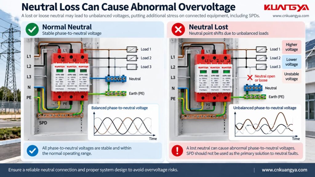
Extra care is required here.
Most discussion of power-frequency TOV relates to AC systems.
A PV DC system has different operating conditions.
Important PV DC concerns include:
| PV consideration | なぜそれが重要なのか |
|---|---|
| Maximum string Voc | Determines maximum DC voltage |
| Low-temperature Voc increase | Can raise actual open-circuit voltage |
| Ucpv | Must match the PV application |
| PV earthing configuration | Changes voltage relationships to earth |
| Inverter topology | Influences system behavior |
| Insulation faults | Can change conductor-to-earth voltage |
| Correct PV SPD standard | AC SPD assumptions cannot simply be transferred |
IEC 61643-31:2018 specifically covers SPDs intended for the DC side of PV installations up to DC1500V. IEC 61643-41:2025 now covers general DC low-voltage SPDs up to 1500 V DC, but it explicitly excludes PV applications, which remain within IEC 61643-31.
Therefore, do not take an AC TOV number from a 230/400 V AC SPD datasheet and assume the same rule applies to a 1000 V or 1500 V PV SPD.
For PV systems, check the exact:
Ucpv + topology + protection mode + manufacturer documentation + applicable PV SPD standard.
For voltage selection, see our DC SPD voltage selection guide. For grounded versus floating PV arrangements and protection paths, see 2P vs 3P DC SPD for Solar PV.
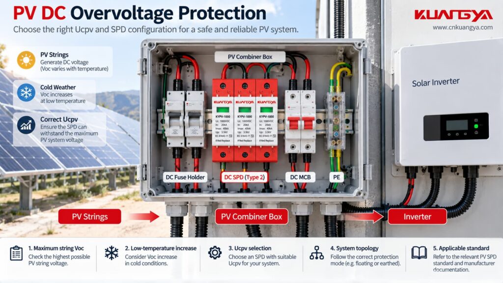
This is another reason AC and DC SPDs should not be interchanged casually.
| 質問 | AC SPD | PV DC SPD |
|---|---|---|
| Main supply | AC power system | PV DC circuit |
| Main continuous-voltage rating | ウク | Ucpv |
| Relevant product standard | IEC 61643-11 | IEC 61643-31 |
| Natural current zero crossing | Present each AC half-cycle | No equivalent periodic zero crossing |
| System topology considerations | TN/TT/IT etc. | Grounded/floating PV topology etc. |
| Can ratings be transferred directly? | - | いいえ |
IEC currently lists IEC 61643-11:2025 for AC low-voltage SPDs, while IEC 61643-31:2018 addresses PV DC SPDs. For a practical explanation of why an AC-only SPD should not simply be moved to a DC circuit, see What Happens If You Use an AC SPD on a DC System?.
| 間違い | Why it is wrong |
|---|---|
| “Any overvoltage is a surge.” | Event duration and origin matter |
| “40 kA means it can handle stronger mains voltage.” | kA surge rating is not TOV withstand |
| “A lower Up means better TOV performance.” | Up and TOV are different characteristics |
| “If the SPD disconnects, the load is safe.” | Parallel SPD disconnection may leave the load energized |
| “A bigger SPD fixes neutral loss.” | Neutral fault must be corrected |
| “The breaker will always trip on overvoltage.” | Standard breakers respond primarily to current |
| “Higher Uc is always better.” | Uc must be coordinated with system voltage and protection objectives |
| “AC and DC overvoltage behavior is the same.” | Circuit behavior and product standards differ |
Instead of starting with:
“How many kA do I need?”
start with the electrical system.
| Selection step | What to confirm |
|---|---|
| 1 | AC or DC application |
| 2 | 公称系統電圧 |
| 3 | 最大連続使用電圧 |
| 4 | Earthing / grounding arrangement |
| 5 | 保護モード |
| 6 | Uc or Ucpv |
| 7 | Manufacturer-declared TOV behavior where applicable |
| 8 | 上へ |
| 9 | SPDタイプ |
| 10 | In / Imax / Iimp |
| 11 | Prospective short-circuit conditions |
| 12 | Backup fuse or breaker requirements |
| 13 | Installation conductor length |
| 14 | Status indication / remote signaling requirements |
| 15 | Exact applicable product standard and documentation |
Installation also matters after the product is selected. Long SPD connecting conductors can increase the voltage appearing at the protected equipment during a fast surge; see our guide to SPD distance from the inverter and SPD lead length.
This order avoids a common purchasing mistake:
choosing the largest kA number first and checking voltage compatibility later.
Assume an electrician installs a new Type 2 SPD.
A few days later the status window indicates replacement.
A new cartridge is installed.
It fails again.
It would be easy to conclude:
“The SPD quality is poor.”
But that is only one possibility.
A better troubleshooting sequence is:
| チェック | Reason |
|---|---|
| Measure actual supply voltage | Identify sustained abnormal voltage |
| Confirm nominal system voltage | Ensure the correct SPD was selected |
| Verify Uc | Detect voltage-rating mismatch |
| ニュートラル導通のチェック | Find neutral displacement risk |
| Confirm earthing configuration | Ensure correct SPD arrangement |
| Inspect wiring | Exclude installation errors |
| Check backup protection | Verify fault coordination |
| Review event history | Distinguish lightning/switching from TOV |
| Check other phases | Identify unbalanced voltage |
| Review manufacturer TOV data | Determine whether the event exceeded design conditions |
Only after these checks should repeated SPD replacement be treated as a simple product issue.
In some installations, yes.
They solve different problems.
Think of them this way:
SPD:
“What happens if a very fast surge arrives?”
Voltage monitoring protection:
“What happens if the supply voltage remains abnormal?”
A system containing both functions may therefore provide broader protection than either one alone.
But the exact protection design depends on the installation, applicable codes and equipment requirements.
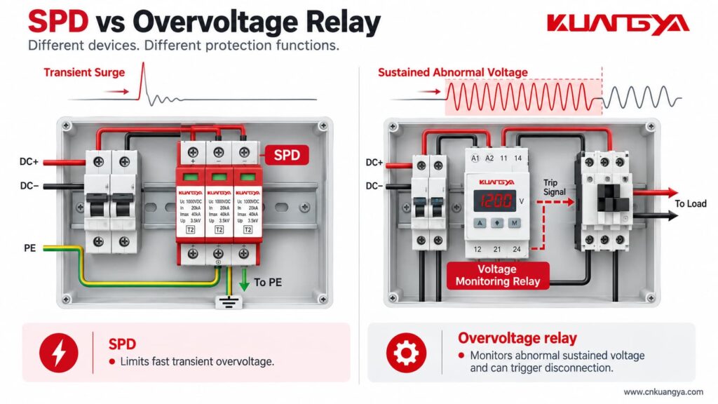
Before approving an SPD specification, confirm the following:
| チェック | はい/いいえ |
|---|---|
| Is the SPD intended for AC or PV DC? | □ |
| Does Uc/Ucpv suit the actual maximum operating voltage? | □ |
| Is the system earthing configuration known? | □ |
| Are the required protection modes identified? | □ |
| Has the TOV behavior been checked where relevant? | □ |
| Is Up suitable for the protection concept? | □ |
| Are In/Imax/Iimp understood correctly? | □ |
| Is backup protection coordinated? | □ |
| Are short-circuit conditions known? | □ |
| Is the installation wiring short and direct? | □ |
| Is neutral integrity verified? | □ |
| Is separate sustained-overvoltage protection required? | □ |
| Does the documentation match the exact SPD model? | □ |
An SPD primarily protects against transient overvoltage, such as short-duration surges caused by lightning effects or switching events. It should not automatically be treated as protection against every temporary or sustained abnormal supply voltage. If the supply voltage remains excessively high, separate voltage monitoring or disconnection protection may be required.
It depends on the SPD and the specific TOV condition.
The datasheet or manufacturer documentation may specify TOV withstand or behavior for defined voltage, duration and connection conditions.
Do not assume that every SPD will survive every TOV.
The result depends on how far the voltage exceeds Uc, how long it lasts and the SPD design.
In an MOV-based SPD, excessive continuous voltage can increase MOV current and heating.
This may eventually cause thermal disconnection or damage.
そうだ。.
A lightning-related surge is a short transient event.
A TOV lasts much longer and is usually associated with a power-system abnormality.
The stresses placed on an SPD are therefore very different.
そうだ。.
Imax is a surge-current parameter.
TOV behavior must be evaluated separately.
That question cannot be answered from 40 kA.
You need to know the nominal system voltage, Uc, connection mode, TOV declaration, duration of the abnormal voltage and the SPD design.
Do not rely on an SPD alone.
A broken or displaced neutral can create dangerous abnormal phase-to-neutral voltages.
Neutral integrity must be restored, and where required a dedicated voltage-monitoring and disconnection function should be used.
そうだ。.
A conventional circuit breaker protects primarily against overcurrent and short circuit.
An SPD limits transient overvoltage.
They perform different functions.
そうだ。.
A voltage-monitoring relay can detect abnormal RMS voltage and initiate a switching action.
It does not replace the high-speed surge-diversion function of an SPD.
だから, does an SPD protect against overvoltage?
The technically correct answer is:
An SPD protects against transient overvoltage, but it should not be treated as universal protection against every temporary or sustained abnormal voltage condition.
Surge current ratings such as In, Imax and Iimp describe transient performance.
Uc/Ucpv describes continuous voltage compatibility.
上へ describes surge-voltage limitation.
And TOV behavior describes how the SPD responds to a specified temporary abnormal-voltage condition.
These parameters should never be treated as interchangeable.
Real-world research also shows why the distinction matters. NIST/EPRI investigations found dramatically different SPD responses to temporary-overvoltage conditions, ranging from survival to internal failure depending on the device and the applied stress.
The practical rule is simple:
First identify the electrical event. Then select the protection function.
Use an SPD for transient surge protection.
Use appropriate voltage monitoring or disconnection when persistent abnormal supply voltage must be detected and removed.
And if SPDs repeatedly fail, investigate system voltage, neutral condition, earthing, Uc/Ucpv and TOV conditions before simply replacing the module again.
For PV applications, always verify the exact SPD model against the system’s maximum DC voltage, PV topology and applicable IEC 61643-31 requirements.

