Zone industrielle WengYang Yueqing Wenzhou 325000
Heures de travail
Du lundi au vendredi : de 7h00 à 19h00
Le week-end : 10H00 - 17H00
Zone industrielle WengYang Yueqing Wenzhou 325000
Heures de travail
Du lundi au vendredi : de 7h00 à 19h00
Le week-end : 10H00 - 17H00

Une question courante après un orage, une manœuvre de commutation ou une surtension inattendue est la suivante : un parafoudre doit-il être remplacé après une surtension ?
La réponse courte est non, pas automatiquement.
Un parafoudre est conçu pour limiter les surtensions transitoires et dériver le courant de choc. Si la surtension reste dans les capacités du parafoudre et que l'appareil n'a pas atteint sa fin de vie, il peut continuer à protéger le système après l'événement.
Cependant, une surtension sévère, des contraintes électriques répétées, une surtension temporaire, une surchauffe ou une dégradation à long terme peuvent endommager les composants de protection à l'intérieur d'un parafoudre. Dans ces cas, le module de protection peut se déconnecter en interne et le parafoudre peut nécessiter un remplacement.
La question correcte n'est donc pas simplement :
“Le parafoudre a-t-il subi une surtension ?”
C'est :
“Quel est l'état du parafoudre après la surtension ?”
Ce guide explique ce qui arrive à un parafoudre lors d'une surtension, comment reconnaître les signes de dommages, ce que signifie réellement un indicateur d'état vert ou rouge, et quand vous devez remplacer le module de protection ou le parafoudre complet.
La nécessité de remplacer un parafoudre dépend de son état après l'événement.
| État du parafoudre après la surtension | Le remplacer ? | Action recommandée |
|---|---|---|
| Indication d'état normal et aucun dommage visible | Pas automatiquement | Poursuivre l'inspection conformément aux instructions du fabricant |
| Indication rouge ou de fin de vie | Habituellement oui | Remplacer le module ou le parafoudre concerné selon les spécifications du fabricant |
| La signalisation à distance signale un défaut | Enquêter immédiatement | Vérifier l'état du parafoudre et le circuit de contact à distance |
| Marques de brûlure, fonte ou décoloration importante | Oui | Isoler le circuit si nécessaire, remplacer le parafoudre endommagé et rechercher la cause |
| Boîtier fissuré ou déformé | Oui | Ne pas continuer à utiliser le parafoudre endommagé |
| Une cartouche remplaçable a atteint sa fin de vie | Habituellement la cartouche | Inspecter la base et utiliser le module de remplacement approprié |
| Événement de foudre majeur mais l'indicateur reste normal | Pas automatiquement | Effectuer une inspection plus détaillée |
| Le parafoudre de remplacement tombe prématurément en panne de manière répétée | Ne vous contentez pas de le remplacer systématiquement | Enquêter sur la tension du système, les surtensions temporaires (TOV), le choix du parafoudre, le câblage et les conditions d'installation |
Le point important est que un événement de surtension ne constitue pas à lui seul une indication de fin de vie.
L'état réel du parafoudre et les instructions de maintenance du fabricant doivent déterminer la marche à suivre.
Regardez cette brève explication avant de décider s'il faut remplacer un parafoudre après une surtension.
Pour comprendre pourquoi un parafoudre ne doit pas nécessairement être remplacé après chaque surtension, il est utile de comprendre ce que fait réellement l'appareil.
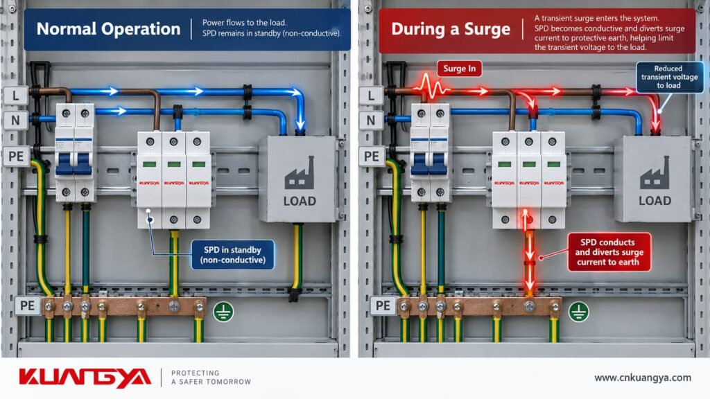
De nombreux parafoudres sont connectés en parallèle avec le circuit qu'ils protègent.
En tension de fonctionnement normale, les composants limiteurs de tension à l'intérieur du parafoudre restent dans un état à haute impédance. Le courant de charge normal n'a donc pas besoin de circuler à travers l'élément de protection du parafoudre.
C'est aussi pourquoi les parafoudres sont normalement installés en parallèle plutôt que d'être simplement placés en série avec la charge.
Lorsqu'une surtension transitoire atteint le parafoudre, ses composants de protection réagissent.
Dans un parafoudre à base de varistance à oxyde métallique (MOV), la varistance passe d'un état à haute impédance à un état conducteur lorsque la tension dépasse sa plage de fonctionnement.
Le parafoudre permet alors de :
limiter la tension transitoire
et
dériver le courant de surtension loin des équipements sensibles.
Lorsque l'événement transitoire se termine, l'élément de protection revient normalement à son état à haute impédance.
Ce principe de fonctionnement est fondamental pour les parafoudres : ils contiennent des composants non linéaires conçus pour limiter la tension de surtension et dériver le courant de surtension. Les exigences actuelles de la norme CEI utilisent la même définition de base.
Par conséquent, le fait qu'un parafoudre ait fonctionné lors d'une surtension ne signifie pas en soi qu'il est défaillant.
Pas nécessairement.
Le résultat dépend de facteurs tels que :
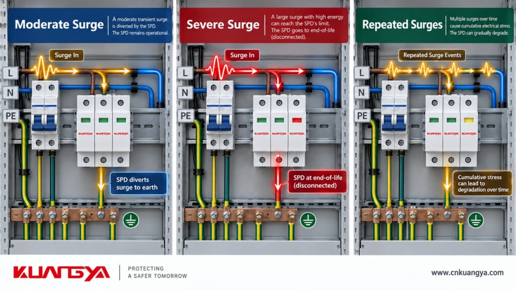
Une surtension qui reste dans les limites de capacité du parafoudre peut être gérée sans que le dispositif n'atteigne sa fin de vie.
Un événement beaucoup plus grave peut causer des dommages importants en une seule occurrence.
Un parafoudre est conçu pour réagir aux surtensions transitoires.
Si un événement reste dans les limites de fonctionnement et de capacité de gestion des surtensions prévues pour le produit, le parafoudre peut continuer à fonctionner par la suite.
C'est pourquoi il serait incorrect d'appliquer une règle telle que :
“ Une surtension = un remplacement. ”
Le dispositif doit être évalué en fonction de son état réel.
Un événement suffisamment sévère peut entraîner l'atteinte de la fin de vie de l'élément de protection en une seule occurrence.
Selon la conception du parafoudre (SPD), cela peut entraîner :
Le comportement exact en cas de défaillance varie selon la conception du produit.
La dégradation du parafoudre ne se limite pas non plus à un seul événement de foudre spectaculaire.
Des contraintes électriques répétées peuvent progressivement affecter les caractéristiques électriques d'une varistance (MOV).
Cependant, cela ne doit pas être décrit comme un simple compte à rebours d'énergie fixe où chaque surtension réduit la durée de vie restante d'une quantité identique.
La dégradation des MOV dépend de l'amplitude, de la durée, de la répétition, de la tension de fonctionnement, de la température et d'autres contraintes appliquées au composant. La norme IEC TR 61643-333:2026 traite spécifiquement des équations caractéristiques et de l'évaluation de la durée de vie des MOV à oxyde de zinc, illustrant que la durée de vie d'un MOV est plus complexe qu'un simple “ bilan énergétique ” fixe.”
Many Type 2 SPDs use metal oxide varistors as their primary voltage-limiting elements.
Under normal voltage, an MOV has high resistance.
When the applied voltage rises sharply during a transient event, the MOV becomes conductive and helps limit the voltage.
Over time, electrical and thermal stress can change the MOV’s characteristics.
A simplified aging path may look like this:
Repeated electrical stress
↓
Change in MOV characteristics
↓
Possible increase in leakage current
↓
Additional heating
↓
Thermal protection operates if necessary
↓
Protection element disconnects
↓
SPD indicates an end-of-life or fault condition
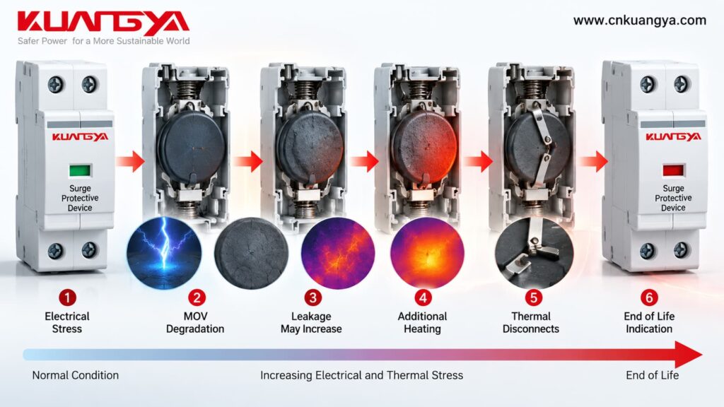
The precise sequence depends on the SPD design.
Modern MOV-based SPDs commonly include thermal protection because an MOV that becomes unstable or overheated must be safely disconnected from the power system.
For example, Schneider Electric describes some of its SPDs as using thermally protected MOVs and instructs replacement of the module when the corresponding indication shows loss of protection.
This internal disconnection is one reason a failed SPD can sometimes leave the protected equipment powered while surge protection for that mode is no longer available.
There is no single inspection method that applies identically to every SPD.
If you are not sure whether an SPD has failed, see our guide on comment savoir si un parafoudre est défectueux.
However, the following signs usually justify replacement or further investigation.
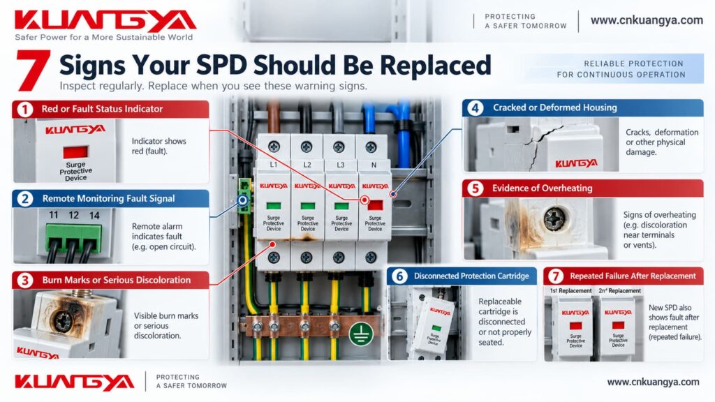
For many pluggable DIN-rail SPDs, the front status window provides the fastest visual indication of the protection module’s condition.
Une disposition courante est :
Normal indication → protection element has not reported end of life
Red/fault indication → affected module requires replacement
Par exemple, ABB describes mechanical SPD indicators that change from green to red at end of life and states that once this occurs, the SPD should be changed because protection is no longer guaranteed.
However, indicator colors and meanings are product-specific.
Always check the markings, datasheet, or instructions for the exact SPD you are inspecting.
Do not assume that every SPD from every manufacturer uses the same color logic.
Some SPDs include remote signaling terminals, often using a changeover dry contact with terminals such as:
COM
NON
NF
These contacts allow the SPD’s status to be reported remotely to equipment such as:
When the monitored SPD reaches the state defined by the manufacturer, the remote contact changes state.
But a remote alarm should still be verified.
Check:
The remote contact tells you about the monitored SPD state. It does not directly measure the SPD’s actual surge-clamping performance.
Visible heat damage is not a normal service condition.
Warning signs include:
If these conditions are present, the SPD should not simply be returned to service because its indicator still appears normal.
The circuit should be made safe according to the applicable electrical procedure, and both the SPD and surrounding installation should be inspected.
The cause also matters.
Replacing the SPD without identifying a wiring problem, abnormal system voltage, short-circuit condition, or other fault can result in another failure.
A cracked housing may result from:
Even if the internal condition cannot be seen, physical enclosure damage is a reason to treat the SPD as suspect.
An electrical protection device depends not only on its MOV or other internal component but also on proper insulation, spacing, mechanical connections, and safe containment.
If these have been compromised, replacement is normally the safer maintenance decision.
Not every internal problem immediately produces an obvious red indicator.
If you notice:
disconnect and investigate the equipment using the required safe electrical procedure.
Do not continue using an SPD simply because power is still reaching the protected equipment.
A parallel-connected SPD can lose its protective function while the main circuit continues supplying the load.
Many modular SPDs use plug-in cartridges.
If an internal disconnector has operated and the cartridge indicates end of life, the affected cartridge normally needs replacement.
That does not necessarily mean the complete SPD base must always be replaced.
If:
the manufacturer may allow replacement of the cartridge only.
Schneider Electric, for example, provides model-specific replacement modules for certain modular SPD families rather than requiring replacement of every part of the assembly.
But never assume that a pluggable SPD cartridge is automatically safe to remove while energized.
Pluggable does not mean hot-swappable.
Follow the manufacturer’s instructions and the required electrical isolation procedure before servicing the SPD.
One of the most important warning signs is not the first failure.
Il s'agit de repeated early failure after replacement.
If a newly installed SPD quickly reaches its fault or end-of-life condition again, simply installing another identical device may not solve the problem.
Investigate possible causes such as:
For PV applications, correct voltage selection is especially important. See how to select the correct DC SPD voltage rating for a solar PV system.
Current IEC SPD requirements specifically consider system and fault conditions such as expected short-circuit current and temporary-overvoltage stresses when evaluating SPD applications.
Repeated failure should therefore be treated as a system-level troubleshooting problem, not merely a replacement problem.
Usually, a manufacturer-defined normal indication means the SPD has not reported its end-of-life condition through that indicator mechanism.
For a deeper explanation, see what an SPD green indicator can and cannot tell you about the protection condition.
But there is an important distinction:
Normal indicator ≠ exact measurement of remaining SPD life.
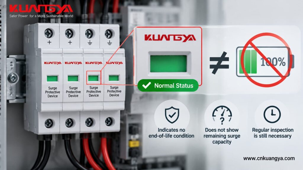
A basic mechanical indicator normally does not tell you:
So avoid statements such as:
“Green means the SPD is 100% healthy.”
ou
“Green means the SPD has full surge capacity remaining.”
A more technically accurate interpretation is:
The SPD’s normal status indication shows that its internal monitoring or disconnection mechanism has not indicated end of life according to the product design.
That is useful information—but it is not the same as a complete electrical performance test.
ABB’s guidance illustrates this distinction well: the mechanical indicator is specifically an end-of-life indicator, changing state when the device reaches the defined replacement condition.
Not automatically—but the inspection should be more thorough.
The words “lightning event” can describe very different electrical stresses.
A distant lightning event that induces a relatively small transient is not the same as a severe nearby or direct lightning-current event.
The correct SPD type and coordinated protection system also matter.
For example, a Type 2 SPD is primarily tested for surge-current conditions different from those associated with the lightning-current testing of a Type 1 SPD.
So after a known major event, check more than just the color window.
Inspect:
If nearby electrical equipment has also been damaged, or the lightning event was unusually severe, a more detailed electrical inspection is justified even when the status window has not changed.
For critical installations, follow the site’s maintenance plan, lightning-protection procedure, and manufacturer-specific recommendations.
For modular SPDs, a failed cartridge does not always require replacing the complete assembly.
Use the physical condition of the base and the manufacturer’s instructions to make the decision.
| Condition | Replace cartridge only | Replace complete SPD |
|---|---|---|
| One plug-in module reaches end of life | Usually | Not normally necessary if base is sound |
| Base contacts remain clean and undamaged | Usually | Non |
| Base contacts are burned or damaged | Non | Oui |
| Base or housing has melted | Non | Oui |
| Severe corrosion is present | Non | Usually |
| Mechanical locking system is damaged | Non | Oui |
| Correct compatible cartridge is unavailable | Non | Oui |
| Extent of damage cannot be confidently determined after a serious failure | Not preferred | Consider complete replacement |
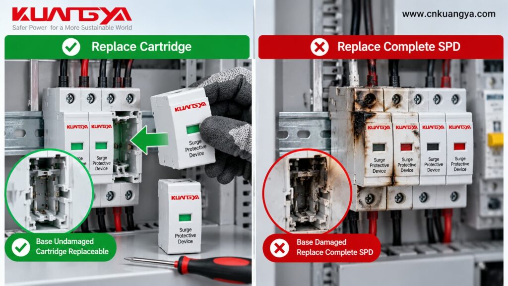
La règle la plus importante est :
Replace only what the manufacturer allows you to replace.
A cartridge from a different series may physically look similar while having a different Uc, discharge rating, protection level, internal circuit, or coding system.
Always use the specified replacement module.
A practical post-surge inspection can follow seven basic steps.
Start with the front status window.
Look for the manufacturer-defined normal, fault, or end-of-life condition.
If the SPD includes remote contacts, verify whether the monitoring system has received a fault signal.
Compare the result with the manufacturer’s COM/NO/NC diagram.
Vérifier pour :
For a modular SPD, inspect both the plug-in cartridge and the base.
A new cartridge should not be installed into a heat-damaged or mechanically damaged base.
Loose or heat-damaged conductors can affect both safety and surge protection.
Also check the SPD connection conductors and protective-earth connection according to the installation instructions.
In solar PV systems, the distance between the SPD and inverter and the connection lead length can also affect practical surge protection performance.
Ask what happened before the SPD changed state.
Was there:
This information can help distinguish normal end-of-life behavior from a broader installation problem.
If the SPD has reached its defined end-of-life state or shows physical damage, replace the affected component according to the manufacturer’s instructions.
If the condition is uncertain and the application justifies deeper verification, use the appropriate professional SPD testing method or manufacturer-approved test equipment.
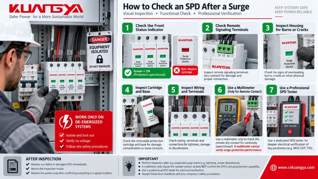
A multimeter can be useful around an SPD, but it cannot fully prove that the SPD still has its original surge-protection performance.
For example, a multimeter may help with:
But an ordinary multimeter does not reproduce the electrical conditions used to determine major SPD parameters such as:
If these ratings are unfamiliar, our guide des spécifications des parafoudres CC explains Ucpv, In, Imax, Up and other common SPD markings in more detail.
Par conséquent :
A successful multimeter continuity or resistance check is not proof that the SPD still meets its original surge-protection specification.
Professional SPD verification may require dedicated equipment capable of testing the relevant electrical characteristics.
Phoenix Contact, for example, provides dedicated CHECKMASTER equipment for electrical testing of compatible pluggable SPDs and notes that visual inspection alone may not reliably determine an SPD’s functional capability.
Also remember that some electrical tests performed elsewhere in an installation can interact with an SPD.
ABB installation guidance, for example, specifies that the SPD should be disconnected before certain insulation testing because the SPD can respond to the test voltage as though it were an overvoltage.
Always follow the SPD and test-equipment manufacturer’s instructions.
For a more complete inspection procedure, see our guide on comment tester un parafoudre.
There is no universal fixed service life that applies to every SPD.
It would therefore be misleading to say:
“Every SPD must be replaced after three years.”
ou :
“An SPD always lasts ten years.”
Actual service life depends on many variables, including:
A severe event may cause end of life much earlier than expected.
Another SPD in a relatively quiet installation may remain serviceable for many years.
For that reason, condition-based inspection and manufacturer-defined status indications are generally more useful than assigning one universal expiration date.
Use this quick decision guide after a surge event.
Answer these 5 quick questions to check whether your SPD shows an obvious replacement condition or needs further inspection.
Non.
SPDs are designed to respond to transient overvoltages. Experiencing a surge does not automatically mean the SPD has reached end of life.
Replace or service it when the manufacturer’s status indication, inspection results, electrical testing, or physical condition shows that it is no longer serviceable.
Oui.
Many SPDs are designed to withstand multiple surge events within their specified capability.
However, the number and severity of events an SPD can withstand cannot be reduced to one universal number because different surge stresses and product designs produce different effects.
Oui.
A sufficiently severe lightning-related event can cause an SPD to reach end of life in one occurrence.
Whether this happens depends on the actual current and voltage stress reaching the SPD, the SPD type and ratings, installation, and the overall lightning and surge protection system.
It normally means the SPD has not indicated its manufacturer-defined end-of-life state through that indicator.
It should not normally be interpreted as an exact measurement of remaining surge capacity.
Always check the product instructions for the specific meaning of its status window.
For SPDs where red is defined as the end-of-life or replacement indication, yes—the affected module or device should be serviced or replaced according to the manufacturer’s instructions.
ABB, for example, states that when its standard SPD indicator changes from green to red at end of life, the SPD must be changed because protection is no longer guaranteed.
If the SPD uses manufacturer-approved replaceable modules and the base remains undamaged, replacing only the affected cartridge may be permitted.
Check that the replacement module has the correct model, voltage rating, and compatibility.
If the base, terminals, housing, or contacts have been damaged, replace the complete affected assembly as required.
Do not assume that you can.
A pluggable design makes maintenance easier, but it does not automatically mean the module is approved for energized replacement.
Follow the manufacturer’s instructions and the required electrical isolation and safety procedure before removing or installing an SPD module.
Not completely.
A multimeter may help test remote contacts or perform limited circuit checks, but it cannot reproduce the surge test conditions needed to verify the SPD’s full protection performance.
Dedicated test equipment or manufacturer-defined electrical testing may be required for more detailed verification.
Do not replace an SPD simply because a surge occurred.
An SPD is specifically designed to respond to transient overvoltage events, and one surge does not automatically mean the device has reached end of life.
Instead, base the decision on the actual condition of the SPD.
Replacement is normally justified when:
A normal status indication and the absence of physical damage generally mean there is no obvious end-of-life indication, but they do not provide an exact measurement of remaining surge capacity.
And if an SPD repeatedly fails shortly after replacement, do not simply install another one.
Investigate the system voltage, Uc or MCOV selection, temporary overvoltage conditions, electrical configuration, wiring, backup protection, and the severity of the surge environment.
The best replacement decision is therefore based not on:
“Did a surge happen?”
but on:
“What does the SPD condition tell us after the surge?”
KUANGYA provides AC and DC surge protective devices for electrical distribution and solar PV applications, including modular designs with visual status indication and optional remote signaling functions for easier inspection and maintenance.
For photovoltaic DC applications, SPD selection should consider factors such as maximum PV system voltage, Ucpv, SPD type, discharge-current ratings, voltage protection level, system configuration, and installation position.
PV-side SPDs are specifically addressed by IEC 61643-31 for photovoltaic installations up to 1500 V DC.
If you need help selecting a replacement SPD, send us your:
AC or DC application + system voltage + required SPD type + quantity
and KUANGYA can help you check a suitable model.

