WengYang Industriegebiet Yueqing Wenzhou 325000
Arbeitszeiten
Montag bis Freitag: 7AM - 7PM
Am Wochenende: 10AM - 5PM
WengYang Industriegebiet Yueqing Wenzhou 325000
Arbeitszeiten
Montag bis Freitag: 7AM - 7PM
Am Wochenende: 10AM - 5PM

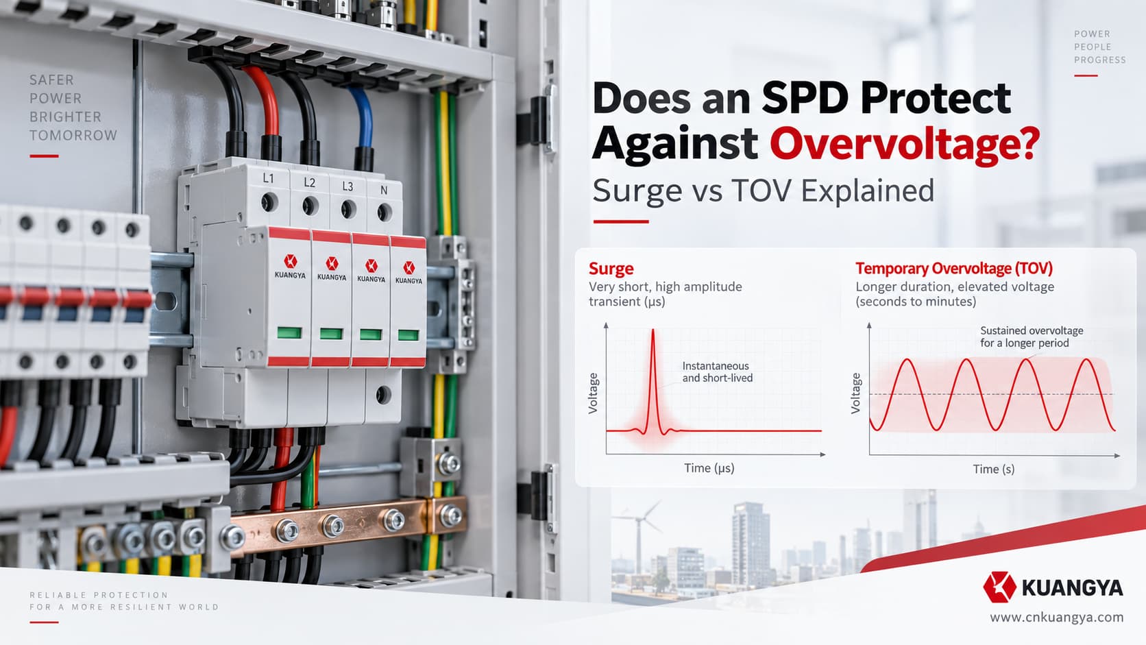
Schützt ein SPD vor Überspannung? Ja, aber die Antwort hängt davon ab, um welche Art von Überspannung es sich handelt. Ein Überspannungsschutzgerät ist in erster Linie dazu ausgelegt, transiente Überspannungen zu begrenzen, während temporäre Überspannungen (TOV) und dauerhafte anormale Spannungen eine andere Betrachtungsweise erfordern.
Der Begriff “Überspannungsschutz” kann irreführend sein, da nicht jede Überspannung ein transienter Stoß ist.
Betrachten Sie drei Situationen:
Ein blitzinduzierter Überspannungsimpuls erreicht eine Schalttafel nur für einen winzigen Bruchteil einer Sekunde.
Die Versorgungsspannung steigt aufgrund eines Netzfehlers für mehrere Sekunden signifikant an.
Oder ein loser Neutralleiter führt dazu, dass eine anormale Spannung an einem Teil der Anlage anliegt, bis der Fehler behoben ist.
Alle drei beinhalten Überspannung, aber es handelt sich nicht um dasselbe elektrische Ereignis.
Und ein SPD reagiert nicht auf alle in der gleichen Weise.
Der wichtigste Unterschied ist folgender:
Ein herkömmlicher SPD ist primär dazu ausgelegt, transiente Überspannungen zu begrenzen. Er sollte nicht automatisch als Schutz gegen temporäre oder anhaltende anormale Versorgungsspannung betrachtet werden.
Diese Unterscheidung beeinflusst die Auswahl des SPD, die Fehleranalyse und sogar die Art und Weise, wie Ingenieure ein beschädigtes SPD interpretieren.
IEC 61643-01:2024 definiert Niederspannungs-Überspannungsschutzgeräte (SPDs) als Geräte, die mindestens ein nichtlineares Bauelement enthalten und dazu bestimmt sind, Stoßspannungen zu begrenzen und Stoßströme abzuleiten. Für AC-Niederspannungsstromversorgungssysteme sind die Produktanforderungen festgelegt in IEC 61643-11:2025.
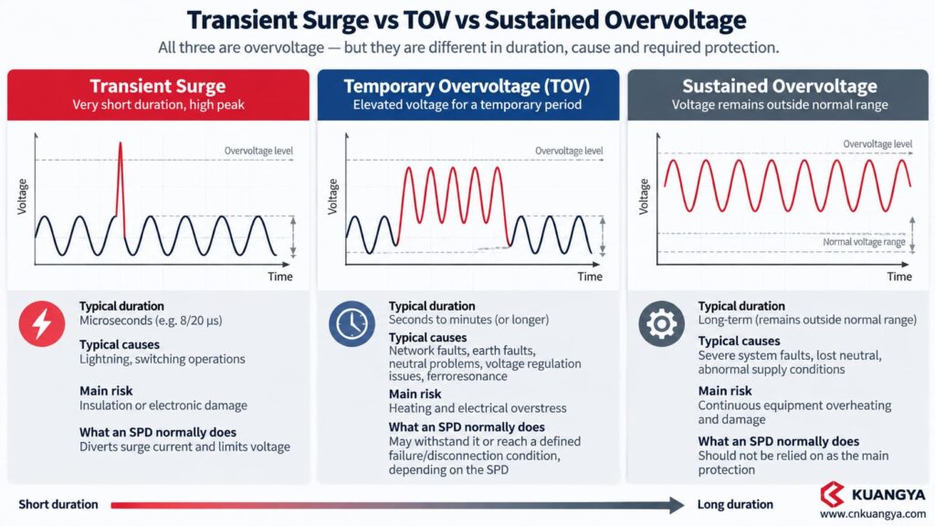
Ja – aber nur vor bestimmten Arten von Überspannung.
Ein SPD ist hauptsächlich ausgelegt für Transiente Überspannungen, wie sie durch Blitzeinwirkungen oder Schaltvorgänge verursacht werden.
Es ist normalerweise nicht dazu bestimmt, die Versorgungsspannung zu regeln oder Lasten zu trennen, solange die Effektivspannung zu hoch bleibt.
Die folgende Tabelle zeigt den grundlegenden Unterschied.
| Elektrischer Zustand | Typische Charakteristik | Hauptrisiko | Was ein SPD normalerweise bewirkt |
|---|---|---|---|
| Transiente Überspannung | Sehr kurzer Impuls | Isolations-/Elektronikschaden | Leitet Stoßströme ab und begrenzt die Spannung |
| Vorübergehende Überspannung (TOV) | Erhöhte netzfrequente Spannung für einen begrenzten Zeitraum | Erwärmung und elektrische Überbeanspruchung | Kann je nach SPD standhalten oder einen definierten Ausfall-/Abschaltzustand erreichen |
| Anhaltende anormale Spannung | Versorgung bleibt außerhalb des normalen Betriebsbereichs | Kontinuierliche Überhitzung/Beschädigung der Betriebsmittel | Sollte nicht als Hauptschutzmaßnahme verwendet werden |
| Unterspannung | Versorgungsspannung fällt unter den normalen Bereich | Fehlfunktion von Motoren/Betriebsmitteln | Herkömmliche Überspannungsschutzgeräte (SPD) beheben dies nicht |
| Überstrom / Kurzschluss | Überlast oder Fehlerstrom | Überhitzung von Leitern/Betriebsmitteln | Diese Funktion wird von einer Sicherung oder einem Leitungsschutzschalter übernommen. |
Deshalb ist die Frage:
“Verfügt meine Verteilung bereits über einen Überspannungsschutz (SPD)?”
nicht dasselbe wie:
“Ist meine Anlage gegen jede anormale Spannungsbedingung geschützt?”
Das ist sie nicht.
Das Wort Überspannung ist eine weit gefasste Kategorie.
Das Verständnis der Dauer und der Ursache des Ereignisses ist unerlässlich, bevor entschieden wird, welches Schutzgerät ansprechen soll.
Eine transiente Überspannung ist eine kurzzeitige Spannungsstörung.
Typische Ursachen sind:
Die Standard-SPD-Prüfung verwendet üblicherweise Impuls-Wellenformen wie die 8/20 μs Stromwellenform assoziiert für Typ-2-Anwendungen.
Das Ereignis geschieht extrem schnell.
Dies ist genau die Umgebung, für die ein SPD ausgelegt ist. Wenn Sie den Begrenzungs- und Stromableitungsprozess genauer betrachten möchten, lesen Sie unseren Leitfaden zu wie ein DC-Überspannungsschutzgerät funktioniert.
Eine TOV ist etwas anderes.
Die Spannung bleibt wesentlich länger erhöht als bei einem Impuls und ist im Allgemeinen eher mit dem Stromnetz als mit einer einzelnen Überspannung im Mikrosekundenbereich verbunden.
Mögliche Ursachen können sein:
Die Stärke allein definiert das Risiko nicht.
Spannung + Dauer + Schutzart + Erdungssystem + SPD-Auslegung sind allesamt von Bedeutung.
ABB unterscheidet beispielsweise Uc, zwischen der maximalen Dauerspannung und UT, der temporären Überspannungsfestigkeit. Ihr OVR-Praxisleitfaden behandelt das TOV-Verhalten getrennt von der Stoßstromfestigkeit und zeigt, dass die auftretende Belastung von der Anschlussart des SPD und der Netzkonfiguration abhängt.
Wenn eine anormale Versorgungsspannung andauert, anstatt sich wie ein temporäres Fehlerereignis zu verhalten, ändert sich die technische Problemstellung erneut.
Ein herkömmlicher parallel geschalteter SPD sollte nicht als Spannungsregler verwendet werden.
Ein Gerät zur Überwachung der Effektivspannung (RMS) und zur Einleitung einer Abschaltung ist normalerweise erforderlich, wenn das Konstruktionsziel wie folgt lautet:
Trennung der Last, wenn die Versorgungsspannung dauerhaft über oder unter einem akzeptablen Schwellenwert liegt.
Zum Beispiel Schneider Electric Harmony Spannungsüberwachungsrelais bieten Über- und Unterspannungsüberwachungsfunktionen. Dies ist eine andere Funktion als die Hochgeschwindigkeits-Überspannungsableitungsrolle eines SPD.
This seems contradictory at first.
An SPD may discharge a very large surge current measured in kiloamperes.
This is why asking “does an SPD protect against overvoltage?” requires first identifying whether the event is a transient surge, a TOV, or a sustained abnormal supply condition.
So why could a much smaller abnormal AC voltage damage it?
Die Antwort lautet:
Energy is not determined by current magnitude alone. Time matters.
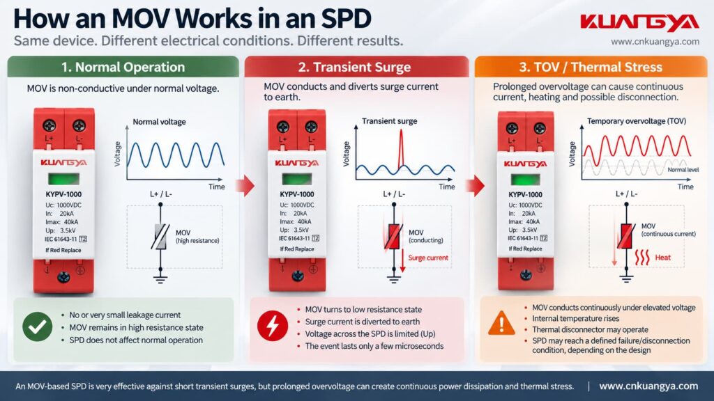
Consider an MOV-based SPD.
Under normal operating voltage, the MOV remains in a high-impedance state and conducts only a very small current.
When a transient surge raises the voltage sufficiently, the MOV becomes conductive.
Surge current is diverted through the SPD and the voltage is limited.
The surge then disappears very quickly.
The MOV returns toward its normal high-impedance state.
A simplified sequence looks like this:
| Bühne | Voltage condition | MOV behavior |
|---|---|---|
| Normal operation | Below its conduction region | High impedance |
| Surge arrives | Voltage rises rapidly | MOV becomes conductive |
| Surge current flows | Very short high-energy event | Energy is absorbed/diverted |
| Surge ends | Voltage returns to normal | MOV returns toward standby |
| TOV persists | Voltage remains abnormally high | Continued conduction may produce heat |
| Excessive thermal stress | Temperature continues increasing | Thermal disconnector may operate or MOV may be damaged |
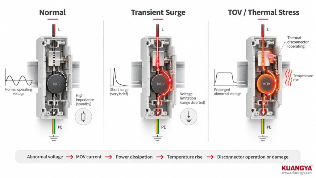
That last condition is the problem.
If the voltage does not disappear quickly enough, the MOV may continue conducting.
Electrical energy then becomes heat.
In simplified form:
abnormal voltage → MOV current → power dissipation → temperature rise → disconnector operation or component damage
This is why:
40 kA Imax does not mean that an SPD can withstand any abnormal supply voltage.
Imax describes a defined surge-current capability.
TOV behavior describes a completely different type of electrical stress.
Another common source of confusion is mixing voltage specifications together.
Suppose an SPD datasheet contains Uc, Nach oben and a TOV/UT specification.
They should not be compared as though they describe the same thing.
| Parameter | Main question it answers | What it does NOT tell you |
|---|---|---|
| Uc / MCOV | What voltage can remain continuously across the SPD under specified conditions? | Surge protection level |
| Nach oben | How much voltage appears at the SPD during standardized surge testing? | Maximum continuous voltage |
| UT / TOV behavior | How does the SPD behave during a specified temporary abnormal voltage condition? | Universal protection against every overvoltage |
| Unter | What nominal surge current is used for the relevant discharge-current test? | TOV withstand |
| Imax | What maximum discharge current is declared for the relevant Type 2 test? | Ability to survive neutral loss |
| Iimp | What impulse-current duty is declared for Type 1 applications? | Sustained-overvoltage protection |
The IEC definition of an SPD focuses on limiting surge voltage and diverting surge current. IEC 61643-12:2020 separately covers selection, operation, location and coordination principles for AC power SPDs. If the differences between Uc, Up, In, Imax and Iscpv are not yet clear, see our Leitfaden für DC-SPD-Spezifikationen.
Not automatically.
It is tempting to think:
Higher Uc = safer SPD.
Das ist zu einfach ausgedrückt.
A suitably higher Uc can give more operating-voltage margin, but SPD selection involves a tradeoff.
The device must remain stable at the expected continuous system voltage while still providing an appropriate surge protection level.
NIST researchers have described this design dilemma for decades: an SPD must provide effective surge limitation without being expected to clamp longer-duration power-frequency overvoltages indefinitely.
Daher:
Do not deliberately oversize Uc simply because you are worried about TOV.
Instead, check:
| Frage | Warum das wichtig ist |
|---|---|
| What is the nominal system voltage? | Establishes basic operating condition |
| What is the maximum expected continuous voltage? | Determines Uc compatibility |
| What is the earthing system? | Influences voltage appearing across protection modes |
| Which protection modes are used? | L-N and L-PE may see different stresses |
| What TOV behavior does the manufacturer declare? | Determines behavior under specified fault conditions |
| What Up is required? | Determines surge-voltage limitation |
| What does the protected equipment tolerate? | Required for insulation coordination |
This is where the distinction stops being theoretical.
A NIST-hosted paper by François Martzloff and Arshad Mansoor discusses actual power-system overvoltage scenarios.
One example cited from an EPRI report involved a power-system switching incident during restoration of power phase by phase.
The recorded condition produced an RMS voltage exceeding 150% of normal voltage for approximately four seconds.
The researchers identified the phenomenon as a temporary overvoltage associated with ferroresonance.
Notice what makes this different from a normal SPD surge event:
| Lightning/switching impulse | Documented TOV case |
|---|---|
| Extremely short | About 4 seconds |
| Typically discussed with impulse waveforms | Power-frequency RMS voltage remained elevated |
| SPD diverts impulse energy | SPD may remain electrically stressed for much longer |
| Surge current rating is important | TOV behavior and continuous-voltage margin become critical |
Four seconds may sound short to a person.
For an MOV that is dissipating abnormal power continuously, it is extremely long compared with a microsecond-scale surge.
Another NIST-hosted TOV study by researchers from Eaton Electrical, EPRI Solutions and François Martzloff investigated what happens when commercial SPDs experience several TOV conditions.
The study intentionally exposed commercial devices to conditions representing real power-system abnormalities.
The test program included the following examples:
| Simulated condition | Applied stress |
|---|---|
| Poor voltage regulation | 1.15 pu / 138 V for 6 hours |
| Power-system fault | 1.3 pu / 156 V for 2 seconds |
| Loss of secondary neutral | 1.5 pu / 180 V for 4 hours |
| Ferroresonance | 2.0 pu / 240 V for 1 minute |
| High-voltage conductor contact with LV system | 3.0 pu / 360 V for 1 second |
The values relate to the study’s 120 V system basis; they must nicht be copied directly as ratings for another SPD or another electrical system.
The result was especially important.
The researchers found that SPD response varied substantially depending on the product design.
The three cord-connected SPD specimens failed under the simulated 1.5 pu neutral-loss condition, while the two permanently connected specimens used in that study survived the first four test scenarios. Under the extreme 3.0 pu test, the permanently connected specimens experienced partial internal failure but retained some protective capability.
This should nicht be interpreted as:
“Hardwired SPDs always survive TOV.”
The study used only a small group of specific products and represents historical designs.
Its real lesson is more useful:
Two products with similar-looking surge ratings may behave very differently under a long-duration abnormal voltage condition.
That is why TOV cannot be judged from Imax alone.
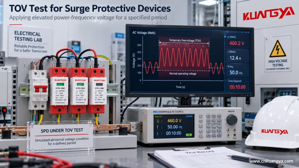
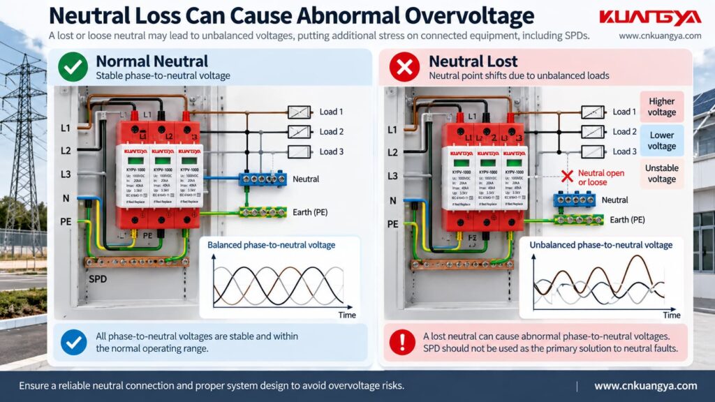
Neutral interruption is one of the most useful examples because it explains why the phrase “the SPD should clamp the voltage” can become dangerous.
In a multi-wire system with unequal phase-to-neutral loads, loss of the neutral can shift the neutral point.
The voltage across individual loads can then become severely unbalanced.
NIST describes loss-of-neutral conditions in North American 120/240 V three-wire systems where one side can approach twice normal voltage depending on the connected load impedances. The paper notes that such neutral problems may result from loose connections, mechanical damage or corrosion.
Now imagine an MOV-based SPD connected across the affected conductors.
If the abnormal power-frequency voltage pushes the MOV into conduction:
it begins conducting continuously.
But an MOV is not supposed to behave like a voltage regulator carrying that current indefinitely.
It may heat rapidly.
Eventually the result may be:
| Possible outcome | What it means |
|---|---|
| SPD withstands the event | Device remains functional within its declared condition |
| Internal thermal disconnector operates | Surge protection on that mode may be lost |
| Backup protection operates | SPD branch may be disconnected |
| MOV suffers damage | Module may require replacement |
| Status indicator changes | Maintenance is required |
| Load remains energized | Equipment may still be exposed to abnormal supply voltage |
The last point is particularly important.
A typical parallel-connected SPD can disconnect itself while the protected circuit remains energized.
Daher:
SPD failure or disconnection does not necessarily remove the abnormal voltage from the load.
A conventional SPD should therefore not be relied on as the sole protection against neutral-loss overvoltage. Where the design requires abnormal RMS voltage to be detected and the load disconnected, a dedicated voltage-monitoring or protection function may be needed. The neutral fault itself must still be located and corrected.
Because doing so could require the SPD to absorb or divert power continuously.
Consider a simplified example.
A Type 2 MOV-based SPD is installed across the supply.
A brief transient occurs.
The MOV conducts for a very short time and then stops.
That is normal.
Now assume abnormal mains voltage remains high for many seconds.
If the MOV attempts to hold the voltage down continuously, the SPD essentially becomes part of a power-frequency current path.
The longer the current flows, the greater the thermal stress.
That can lead to:
thermal runaway → disconnector operation → loss of SPD protection or component damage
This is exactly why SPDs require coordinated fault and disconnection behavior rather than simply “clamping everything.”
This distinction is extremely important when reading datasheets.
Suppose a manufacturer states that an SPD has a certain UT or TOV capability.
That generally describes the SPD’s behavior under specified test conditions.
It does not automatically mean:
“The downstream equipment will remain at normal voltage throughout the TOV.”
These are different functions.
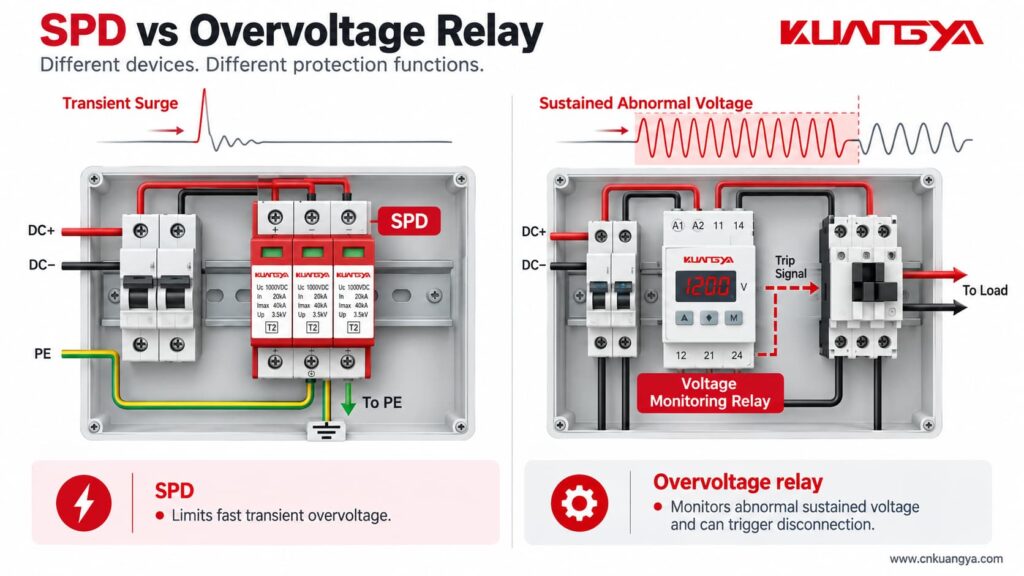
Compare them:
| Funktion | SPD | Voltage monitoring / overvoltage protection |
|---|---|---|
| Detect fast transient surge | Ja | Usually not its primary purpose |
| Divert surge current | Ja | Nein |
| Limit impulse voltage | Ja | Nein |
| Continuously monitor RMS voltage | Not normally its main function | Ja |
| Adjustable OV/UV thresholds | Normally no | Often yes |
| Time-delay operation | Not in the same sense | Gemeinsame |
| Disconnect load during persistent abnormal voltage | Normalerweise nein | Can command or perform disconnection, depending on system design |
Schneider’s Harmony control relays, for example, monitor overvoltage and undervoltage conditions with threshold and timing functions; this is fundamentally different from the shunt surge-diversion function of an SPD.
A standard circuit breaker should not automatically be treated as an overvoltage protector either.
Its primary job is overcurrent protection.
If voltage rises while load current remains below the breaker trip characteristic, an ordinary breaker may remain closed.
That means four devices can perform four different functions:
| Gerät | Primary protection function |
|---|---|
| SPD | Transiente Überspannung |
| Sicherung | Overcurrent / short-circuit protection |
| Leitungsschutzschalter | Overcurrent / short-circuit protection |
| Voltage monitoring relay / dedicated OV protection | Abnormal supply voltage monitoring and disconnection logic |
This is why replacing one device with another based only on the word “protection” is a mistake. For the separate question of SPD overcurrent coordination, see our guide to SPD backup fuse and circuit-breaker selection.
Nein.
Suppose one SPD is rated:
In = 20 kA
Imax = 40 kA
and another says:
Imax = 60 kA
The 60 kA product is not automatically better at surviving a temporary power-frequency overvoltage.
The ratings describe different stresses.
| Parameter | Mainly associated with |
|---|---|
| Unter | Nominal surge discharge duty |
| Imax | Maximum Type 2 discharge-current duty |
| Iimp | Type 1 impulse-current duty |
| Uc | Continuous operating voltage |
| UT / TOV | Temporary abnormal-voltage behavior |
Therefore, if SPDs repeatedly fail without obvious lightning activity, simply purchasing a higher-Imax model may not solve the actual problem.
This is a situation where field diagnosis matters more than changing brands.
Use this investigation table.
| Beobachtung | Check first | Possible explanation |
|---|---|---|
| New SPD quickly turns red | Actual system voltage | Wrong Uc or abnormal supply |
| Several modules fail repeatedly | Neutral and earthing condition | System fault rather than repeated lightning |
| SPD becomes hot | Continuous voltage across SPD | MOV may be conducting abnormally |
| SPD fails after generator operation | Generator voltage/frequency regulation | Abnormal supply condition |
| One phase repeatedly damages an SPD | Phase-to-neutral voltage | Neutral displacement or phase-specific fault |
| SPD survives but equipment fails | Event type and protection coordination | Disturbance may not be a transient the SPD can solve |
| Breaker/fuse trips together with SPD failure | Fault current and backup protection | SPD component may have reached a fault state |
| No lightning was recorded | Do not rule out electrical abnormality | TOV, switching, neutral problems or misapplication are possible |
NIST’s historical analysis lists power-system faults, poor voltage regulation, conductor problems, generator conditions, ferroresonance and loss of neutral among conditions capable of contributing to SPD overvoltage stress. If a device already shows a red indicator, abnormal heating or visible damage, our guide on wie man erkennt, ob ein SPD defekt ist explains the next inspection steps.
Extra care is required here.
Most discussion of power-frequency TOV relates to AC systems.
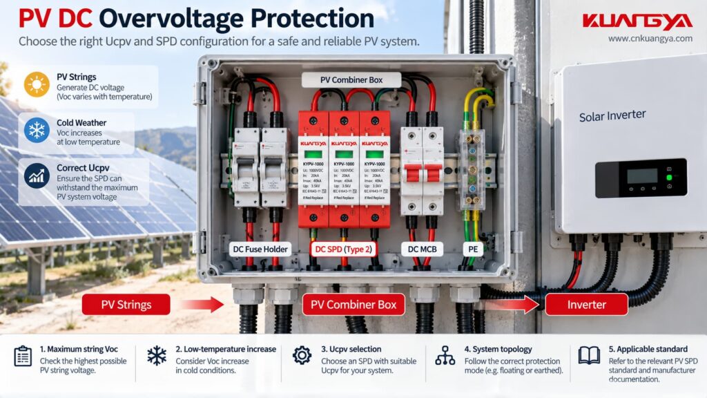
A PV DC system has different operating conditions.
Important PV DC concerns include:
| PV consideration | Warum das wichtig ist |
|---|---|
| Maximum string Voc | Determines maximum DC voltage |
| Low-temperature Voc increase | Can raise actual open-circuit voltage |
| Ucpv | Must match the PV application |
| PV earthing configuration | Changes voltage relationships to earth |
| Inverter topology | Influences system behavior |
| Insulation faults | Can change conductor-to-earth voltage |
| Correct PV SPD standard | AC SPD assumptions cannot simply be transferred |
IEC 61643-31:2018 specifically covers SPDs intended for the DC side of PV installations up to 1500 V DC. IEC 61643-41:2025 now covers general DC low-voltage SPDs up to 1500 V DC, but it explicitly excludes PV applications, which remain within IEC 61643-31.
Therefore, do not take an AC TOV number from a 230/400 V AC SPD datasheet and assume the same rule applies to a 1000 V or 1500 V PV SPD.
For PV systems, check the exact:
Ucpv + topology + protection mode + manufacturer documentation + applicable PV SPD standard.
For voltage selection, see our DC SPD voltage selection guide. For grounded versus floating PV arrangements and protection paths, see 2P vs 3P DC SPD for Solar PV.
This is another reason AC and DC SPDs should not be interchanged casually.
| Frage | AC SPD | PV DC SPD |
|---|---|---|
| Main supply | AC power system | PV DC circuit |
| Main continuous-voltage rating | Uc | Ucpv |
| Relevant product standard | IEC 61643-11 | IEC 61643-31 |
| Natural current zero crossing | Present each AC half-cycle | No equivalent periodic zero crossing |
| System topology considerations | TN/TT/IT etc. | Grounded/floating PV topology etc. |
| Can ratings be transferred directly? | - | Nein |
IEC currently lists IEC 61643-11:2025 for AC low-voltage SPDs, while IEC 61643-31:2018 addresses PV DC SPDs. For a practical explanation of why an AC-only SPD should not simply be moved to a DC circuit, see What Happens If You Use an AC SPD on a DC System?.
| Irrtum | Why it is wrong |
|---|---|
| “Any overvoltage is a surge.” | Event duration and origin matter |
| “40 kA means it can handle stronger mains voltage.” | kA surge rating is not TOV withstand |
| “A lower Up means better TOV performance.” | Up and TOV are different characteristics |
| “If the SPD disconnects, the load is safe.” | Parallel SPD disconnection may leave the load energized |
| “A bigger SPD fixes neutral loss.” | Neutral fault must be corrected |
| “The breaker will always trip on overvoltage.” | Standard breakers respond primarily to current |
| “Higher Uc is always better.” | Uc must be coordinated with system voltage and protection objectives |
| “AC and DC overvoltage behavior is the same.” | Circuit behavior and product standards differ |
Instead of starting with:
“How many kA do I need?”
start with the electrical system.
| Selection step | What to confirm |
|---|---|
| 1 | AC or DC application |
| 2 | Nennspannung des Systems |
| 3 | Maximale Dauerspannung |
| 4 | Earthing / grounding arrangement |
| 5 | Schutzmodi |
| 6 | Uc or Ucpv |
| 7 | Manufacturer-declared TOV behavior where applicable |
| 8 | Nach oben |
| 9 | SPD-Typ |
| 10 | In / Imax / Iimp |
| 11 | Prospective short-circuit conditions |
| 12 | Backup fuse or breaker requirements |
| 13 | Installation conductor length |
| 14 | Status indication / remote signaling requirements |
| 15 | Exact applicable product standard and documentation |
Installation also matters after the product is selected. Long SPD connecting conductors can increase the voltage appearing at the protected equipment during a fast surge; see our guide to SPD distance from the inverter and SPD lead length.
This order avoids a common purchasing mistake:
choosing the largest kA number first and checking voltage compatibility later.
Assume an electrician installs a new Type 2 SPD.
A few days later the status window indicates replacement.
A new cartridge is installed.
It fails again.
It would be easy to conclude:
“The SPD quality is poor.”
But that is only one possibility.
A better troubleshooting sequence is:
| Siehe | Reason |
|---|---|
| Measure actual supply voltage | Identify sustained abnormal voltage |
| Confirm nominal system voltage | Ensure the correct SPD was selected |
| Verify Uc | Detect voltage-rating mismatch |
| Durchgang des Nullleiters prüfen | Find neutral displacement risk |
| Confirm earthing configuration | Ensure correct SPD arrangement |
| Inspect wiring | Exclude installation errors |
| Check backup protection | Verify fault coordination |
| Review event history | Distinguish lightning/switching from TOV |
| Check other phases | Identify unbalanced voltage |
| Review manufacturer TOV data | Determine whether the event exceeded design conditions |
Only after these checks should repeated SPD replacement be treated as a simple product issue.
In some installations, yes.
They solve different problems.
Think of them this way:
SPD:
“What happens if a very fast surge arrives?”
Voltage monitoring protection:
“What happens if the supply voltage remains abnormal?”
A system containing both functions may therefore provide broader protection than either one alone.
But the exact protection design depends on the installation, applicable codes and equipment requirements.
Before approving an SPD specification, confirm the following:
| Siehe | Ja / Nein |
|---|---|
| Is the SPD intended for AC or PV DC? | □ |
| Does Uc/Ucpv suit the actual maximum operating voltage? | □ |
| Is the system earthing configuration known? | □ |
| Are the required protection modes identified? | □ |
| Has the TOV behavior been checked where relevant? | □ |
| Is Up suitable for the protection concept? | □ |
| Are In/Imax/Iimp understood correctly? | □ |
| Is backup protection coordinated? | □ |
| Are short-circuit conditions known? | □ |
| Is the installation wiring short and direct? | □ |
| Is neutral integrity verified? | □ |
| Is separate sustained-overvoltage protection required? | □ |
| Does the documentation match the exact SPD model? | □ |
An SPD primarily protects against transient overvoltage, such as short-duration surges caused by lightning effects or switching events. It should not automatically be treated as protection against every temporary or sustained abnormal supply voltage. If the supply voltage remains excessively high, separate voltage monitoring or disconnection protection may be required.
It depends on the SPD and the specific TOV condition.
The datasheet or manufacturer documentation may specify TOV withstand or behavior for defined voltage, duration and connection conditions.
Do not assume that every SPD will survive every TOV.
The result depends on how far the voltage exceeds Uc, how long it lasts and the SPD design.
In an MOV-based SPD, excessive continuous voltage can increase MOV current and heating.
This may eventually cause thermal disconnection or damage.
Nein.
A lightning-related surge is a short transient event.
A TOV lasts much longer and is usually associated with a power-system abnormality.
The stresses placed on an SPD are therefore very different.
Nein.
Imax is a surge-current parameter.
TOV behavior must be evaluated separately.
That question cannot be answered from 40 kA.
You need to know the nominal system voltage, Uc, connection mode, TOV declaration, duration of the abnormal voltage and the SPD design.
Do not rely on an SPD alone.
A broken or displaced neutral can create dangerous abnormal phase-to-neutral voltages.
Neutral integrity must be restored, and where required a dedicated voltage-monitoring and disconnection function should be used.
Nein.
A conventional circuit breaker protects primarily against overcurrent and short circuit.
An SPD limits transient overvoltage.
They perform different functions.
Nein.
A voltage-monitoring relay can detect abnormal RMS voltage and initiate a switching action.
It does not replace the high-speed surge-diversion function of an SPD.
Also, does an SPD protect against overvoltage?
The technically correct answer is:
An SPD protects against transient overvoltage, but it should not be treated as universal protection against every temporary or sustained abnormal voltage condition.
Surge current ratings such as In, Imax and Iimp describe transient performance.
Uc/Ucpv describes continuous voltage compatibility.
Nach oben describes surge-voltage limitation.
And TOV behavior describes how the SPD responds to a specified temporary abnormal-voltage condition.
These parameters should never be treated as interchangeable.
Real-world research also shows why the distinction matters. NIST/EPRI investigations found dramatically different SPD responses to temporary-overvoltage conditions, ranging from survival to internal failure depending on the device and the applied stress.
The practical rule is simple:
First identify the electrical event. Then select the protection function.
Use an SPD for transient surge protection.
Use appropriate voltage monitoring or disconnection when persistent abnormal supply voltage must be detected and removed.
And if SPDs repeatedly fail, investigate system voltage, neutral condition, earthing, Uc/Ucpv and TOV conditions before simply replacing the module again.
For PV applications, always verify the exact SPD model against the system’s maximum DC voltage, PV topology and applicable IEC 61643-31 requirements.

