منطقة ونغ يانغ الصناعية يويتشينغ ونتشو 325000
ساعات العمل
من الاثنين إلى الجمعة: 7 صباحاً - 7 مساءً
عطلة نهاية الأسبوع 10 صباحاً - 5 مساءً
منطقة ونغ يانغ الصناعية يويتشينغ ونتشو 325000
ساعات العمل
من الاثنين إلى الجمعة: 7 صباحاً - 7 مساءً
عطلة نهاية الأسبوع 10 صباحاً - 5 مساءً

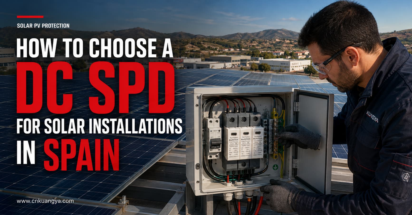
تتعرض الأنظمة الكهروضوئية الشمسية لزيادات مفاجئة في الجهد ناتجة عن نشاط البرق القريب، وعمليات التبديل، والاضطرابات المنقولة عبر الدوائر الكهربائية المتصلة. قد تؤدي هذه الأحداث إلى تلف العواكس، ومعدات المراقبة، وصناديق التجميع، وغيرها من المكونات الحساسة.
يتطلب اختيار جهاز الحماية من زيادة التيار المستمر (DC SPD) للمنشآت الشمسية في إسبانيا أكثر من مجرد مطابقة الجهاز مع الجهد الاسمي للنظام. يجب على المصممين والقائمين بالتركيب مراعاة أقصى جهد للدائرة المفتوحة للخلايا الكهروضوئية، وتصنيف جهاز الحماية (SPD)، وقدرة التفريغ، ومستوى حماية الجهد، ونظام التأريض، وطول الكابلات، وموقع التركيب، والمعايير المعمول بها.
ومع ذلك، فإن اختيار جهاز الحماية من زيادة التيار المستمر (DC SPD) يتضمن أكثر من مجرد مطابقة الجهاز مع الجهد الاسمي للنظام. يجب على المصممين والقائمين بالتركيب مراعاة أقصى جهد للدائرة المفتوحة للخلايا الكهروضوئية، وتصنيف جهاز الحماية (SPD)، وقدرة التفريغ، ومستوى حماية الجهد، ونظام التأريض، وطول الكابلات، وموقع التركيب، والمعايير المعمول بها.
يشرح هذا الدليل كيفية اختيار جهاز الحماية من زيادة التيار المستمر (DC SPD) للمنشآت الشمسية في إسبانيا، ويحدد المعلومات الفنية التي يجب التأكد منها قبل طلب عرض سعر.
يتم تركيب الوحدات الكهروضوئية وكابلات التوصيل الخاصة بها عادةً في مناطق واسعة ومكشوفة. يمكن أن تعمل مسارات كابلات التيار المستمر الطويلة كمسارات تصل من خلالها الجهد الزائد العابر الناتج عن الصواعق وعمليات التبديل إلى العاكس (Inverter).
لا يشترط أن تنشأ زيادة التيار من ضربة صاعقة مباشرة على المصفوفة الكهروضوئية. إذ يمكن للصواعق القريبة أن تحفز جهوداً عابرة في كابلات التيار المستمر، كما أن عمليات التبديل داخل المنشأة قد تؤدي أيضاً إلى حدوث اضطرابات كهربائية.
تم تصميم جهاز الحماية من زيادة التيار المستمر (DC SPD) لـ:
لا يغني جهاز الحماية من زيادة التيار (SPD) عن استخدام المصهر، أو قاطع الدائرة، أو العازل، أو نظام التأريض، أو نظام الحماية الخارجية من الصواعق. يؤدي كل جهاز وظيفة حماية مختلفة ويجب تنسيقها كجزء من التصميم الكامل للنظام الكهروضوئي.
تخضع التركيبات الكهربائية ذات الجهد المنخفض في إسبانيا للائحة الكهروتقنية للجهد المنخفض، والمعروفة باسم (REBT). يجب أن يأخذ التصميم المطبق في الاعتبار أيضاً التعليمات الفنية الحالية، ومواصفات المشروع، والمتطلبات المحلية، والمعايير التي تشير إليها اللائحة.
تتضمن القائمة الرسمية للمعايير الإسبانية المرتبطة بـ (REBT) ما يلي:
بالنسبة لتطبيقات الطاقة الكهروضوئية الدولية، تعد وثائق اللجنة الكهروتقنية الدولية (IEC) التالية مهمة أيضاً:
تنطبق المواصفة IEC 61643-31 على أجهزة الحماية من زيادة التيار (SPDs) المتصلة بجانب التيار المستمر للمنشآت الكهروضوئية ذات جهد مقنن يصل إلى 1500 فولت تيار مستمر.
قد تختلف متطلبات المشروع وفقاً لنوع التركيب، وتقييم المخاطر، والموقع، وتصميم العاكس (Inverter)، ونظام الحماية الخارجية من الصواعق، ومتطلبات السلطات الإسبانية أو القائم بالتركيب المعتمد. لذلك، يجب تأكيد اختيار المنتج من قبل مصمم المشروع أو فني كهربائي مؤهل.
معيار الاختيار الأول هو الحد الأقصى لجهد التشغيل المستمر لجهاز الحماية من اندفاع التيار (SPD) الخاص بالنظام الكهروضوئي، والذي يتم تحديده عادةً بـ Ucpv.
لا تقم باختيار جهاز الحماية من اندفاع التيار (SPD) بناءً على جهد التشغيل الاسمي للعاكس فقط.
يعتمد الحد الأقصى لجهد سلسلة الألواح الكهروضوئية على:
يزداد جهد الألواح الكهروضوئية مع انخفاض درجة الحرارة. لذلك، يمكن أن يكون الحد الأقصى لجهد الدائرة المفتوحة في الظروف الباردة للسلسلة الكاملة أعلى من قيمته في ظروف الاختبار القياسية.
يجب أن يكون جهد التشغيل المستمر لجهاز الحماية من زيادة التيار (Ucpv) مناسباً للحد الأقصى للجهد الذي يمكن أن يظهر بشكل مستمر عبر المصفوفة الكهروضوئية.
| النظام الكهروضوئي | فئة جهد جهاز الحماية من زيادة التيار (SPD) الشائعة | فحص هام |
|---|---|---|
| نظام كهروضوئي سكني صغير | 600 فولت تيار مستمر | تحقق من أقصى جهد للدائرة المفتوحة (Voc) للسلسلة في حالة البرودة |
| أنظمة الطاقة الكهروضوئية السكنية أو التجارية | 1,000 فولت تيار مستمر | تأكد من حدود جهد العاكس (Inverter) وسلسلة الألواح (String) |
| أنظمة الطاقة الكهروضوئية التجارية أو على مستوى المرافق | 1,500 فولت تيار مستمر | استخدم جهاز حماية من اندفاع التيار (SPD) مصمم خصيصاً لأنظمة الطاقة الكهروضوئية بجهد 1,500 فولت |
هذه أمثلة تطبيقية وليست قواعد اختيار تلقائية. يجب أن يعتمد جهد جهاز الحماية من اندفاع التيار (SPD) النهائي على الحد الأقصى المحسوب لجهد النظام الكهروضوئي ومخطط التوصيل الخاص بالشركة المصنعة.
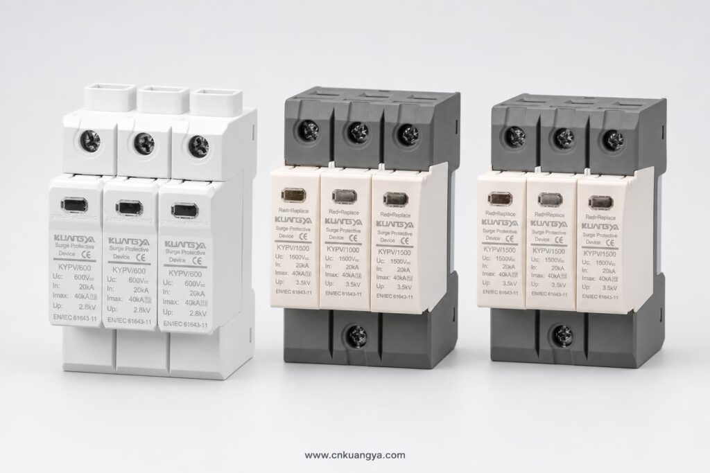
اختيار جهاز حماية من اندفاع التيار (SPD) بجهد تشغيل مستمر (Ucpv) غير كافٍ قد يؤدي إلى التشغيل المبكر أو ارتفاع درجة الحرارة أو الفصل. كما أن اختيار جهد مقنن أعلى من المطلوب دون داعٍ قد يؤدي إلى مستوى حماية من الجهد أعلى وحماية أقل فعالية للمعدات الحساسة.
تُصنف أجهزة الحماية من زيادة التيار (SPD) الخاصة بالأنظمة الكهروضوئية عادةً بناءً على تيار الصواعق الذي صُممت للتعامل معه.
يُستخدم جهاز الحماية من زيادة التيار (SPD) من النوع 2 بشكل شائع للحماية من زيادات التيار الناتجة عن الصواعق المستحثة وفولتية التبديل الزائدة.
تشمل التطبيقات النموذجية ما يلي:
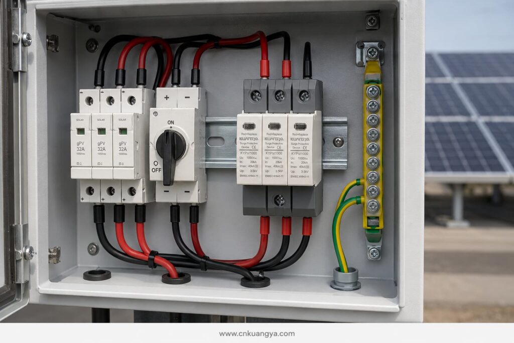
يتم تحديد أجهزة النوع 2 عادةً باستخدام تيار التفريغ الاسمي في وتيار التفريغ الأقصى إيماكس, ، بناءً على شكل موجة تيار 8/20 ميكروثانية.
صُمم جهاز الحماية من زيادة التيار (SPD) من النوع 1 لتفريغ جزء من تيار الصاعقة. وقد يكون مطلوباً في الحالات التي يشير فيها تصميم الحماية من الصواعق إلى إمكانية دخول تيار الصاعقة إلى التمديدات الكهربائية.
يرتبط اختيار النوع 1 عادةً بـ:
يتم التعبير عن قدرة النوع الأول (Type 1) عادةً باستخدام تيار تفريغ النبضة إيمب, ، بناءً على شكل موجة 10/350 ميكروثانية.
يجمع جهاز الحماية من الصواعق (SPD) من النوع 1+2 بين الحماية من تيار الصواعق والارتفاعات المفاجئة الناتجة عن الحث في جهاز واحد.
يمكن اعتباره في الحالات التالية:
يجب اختيار نوع جهاز الحماية من زيادة التيار (SPD) وفقاً لمفهوم الحماية من الصواعق الخاص بالمشروع، ولا ينبغي اختياره لمجرد أن رقم النوع الأعلى يبدو أكثر قوة.
تصف تصنيفات أجهزة الحماية من زيادة التيار (SPD) المختلفة جوانب مختلفة من الأداء.
في يشير إلى التيار الذي يمكن لجهاز الحماية من اندفاع التيار (SPD) من النوع 2 تفريغه بشكل متكرر تحت ظروف الاختبار المحددة، وعادةً ما يستخدم شكل موجة 8/20 ميكروثانية.
يعد أحد التصنيفات الرئيسية المستخدمة عند مقارنة أجهزة الحماية من اندفاع التيار (SPD) من النوع 2.
إيماكس هو أقصى تيار تفريغ بموجة 8/20 ميكروثانية يمكن للجهاز التعامل معه تحت ظروف الاختبار المحددة له.
لا يثبت تصنيف Imax المرتفع وحده أن جهاز الحماية من اندفاع التيار مناسب لتركيب معين. يجب أخذه في الاعتبار جنباً إلى جنب مع In و Up و Ucpv وسلوك الدائرة القصيرة وترتيب التوصيل ومعيار الاختبار المعمول به.
إيمب يُستخدم لأجهزة النوع 1 والنوع 1+2 ويمثل قدرة تحمل تيار نبضة البرق باستخدام شكل موجة 10/350 ميكروثانية.
عند الحاجة إلى حماية من النوع 1، قارن قيمة Iimp لكل قطب أو وضع حماية وفقاً لمواصفات المشروع.
لأعلى يشير إلى الجهد المتبقي الذي يظهر عبر جهاز الحماية من زيادة التيار (SPD) أثناء اختبار التفريغ المحدد.
يجب أن تكون قيمة مستوى الحماية (Up) أقل من مستوى تحمل النبضات للمعدات المراد حمايتها. كما تضيف كابلات التوصيل جهداً إضافياً أثناء حدوث زيادة مفاجئة في التيار، لذا قد يكون مستوى الحماية الفعلي عند العاكس أعلى من القيمة المذكورة في كتالوج جهاز الحماية من زيادة التيار (SPD).
لهذا السبب، تعد التوصيلات القصيرة والمباشرة لجهاز الحماية من زيادة التيار (SPD) أمراً ضرورياً.
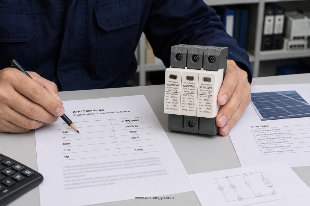
قد تكون دائرة التيار المستمر الكهروضوئية عائمة، أو مؤرضة وظيفياً، أو مهيأة وفقاً لطوبولوجيا معينة للعاكس. يجب أن يستخدم جهاز الحماية من زيادة التيار (SPD) ترتيب توصيل مناسب لهذا النظام.
قبل اختيار عدد الأقطاب أو أوضاع الحماية، تأكد من:
لا تفترض أنه يمكن استخدام جهاز حماية من زيادة التيار (SPD) للتيار المتردد (AC) بجهد مماثل في جانب التيار المستمر (DC) للنظام الكهروضوئي. تتميز الأنظمة الكهروضوئية بخصائص جهد مستمر وتيار خطأ محددة. يجب أن يكون الجهاز مصمماً ومختبراً لتطبيقات التيار المستمر الكهروضوئية وفقاً للمعيار IEC/UNE-EN 61643-31.
يجب أن يكون جهاز الحماية من زيادة التيار الكهروضوئي (PV SPD) قادراً على الفصل بأمان عند وصوله إلى نهاية عمره الافتراضي.
تشمل المعايير المهمة ما يلي:
لا ينبغي اختيار منصهر النسخ الاحتياطي الخارجي بناءً على الحجم المادي لجهاز الحماية من زيادة التيار (SPD) فقط. يجب اتباع ورقة بيانات الشركة المصنعة لجهاز SPD والتحقق من التوافق مع تيار سلسلة الخلايا الكهروضوئية (PV string) وخصائص الأعطال في النظام.
يحمي جهاز SPD من الجهد الزائد العابر، بينما يحمي منصهر gPV أو قاطع التيار المستمر (DC breaker) من ظروف التيار الزائد وقصر الدائرة. لا يمكن لجهاز واحد أن يحل محل الآخر.
تشمل المواقع النموذجية لجهاز SPD للتيار المستمر ما يلي:
يعتمد الترتيب الأنسب على طول الكابل، والتعرض للعوامل الجوية، وتصميم الحماية من الصواعق، ومستوى تحمل المعدات، وتقييم مخاطر المشروع.
بالنسبة للتركيبات المدمجة على الأسطح ذات مسارات كابلات التيار المستمر القصيرة، قد يوفر جهاز الحماية من زيادة التيار (SPD) من النوع 2 بالقرب من العاكس الحماية المطلوبة عند السماح بذلك في التصميم.
بالنسبة للمسارات الأطول بين مصفوفة الخلايا الكهروضوئية والعاكس، قد يلزم استخدام أجهزة حماية من زيادة التيار (SPDs) منسقة عند كلا الطرفين. وهذا يقلل من إجهاد الجهد الذي يمكن أن يتطور على طول الكابل ويحسن الحماية للمعدات في كل موقع.
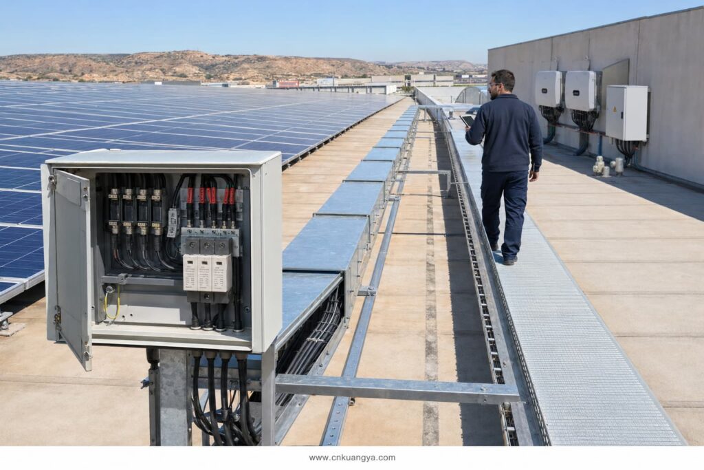
تستخدم بعض توجيهات التصميم الصناعي مسافة 10 أمتار تقريبًا كنقطة يجب عندها النظر في التنسيق الإضافي. لا ينبغي التعامل مع هذا كقاعدة عالمية لكل تركيب في إسبانيا. يجب أن يتبع التنسيب النهائي معيار التصميم المعمول به، وتقييم المخاطر، وتوجيه الكابلات، وتعليمات الشركة المصنعة للمعدات.
حتى جهاز الحماية من زيادة التيار (SPD) المصنف بشكل صحيح يمكن أن يوفر حماية ضعيفة إذا تم تركيبه بكابلات طويلة أو موجهة بشكل سيئ.
أثناء حدوث زيادة في التيار، يؤدي حث الكابل إلى توليد جهد إضافي. وبالتالي، يمكن للموصلات الأطول أن تزيد من الجهد الكلي الذي يصل إلى العاكس.
تتضمن ممارسات التركيب الجيدة ما يلي:
الهدف هو تقليل إجمالي طول التوصيلات وتقليل مستوى الحماية الفعال عند المعدات المحمية.
وحدات حماية التيار المتردد (SPD) المثبتة على سكة DIN لا توفر حماية خارجية تلقائية. تعتمد حمايتها البيئية على الصندوق الذي يتم تركيبها بداخله.
بالنسبة لأنظمة الطاقة الكهروضوئية الموجودة على الأسطح وفي الأماكن الخارجية في إسبانيا، يجب التحقق من:
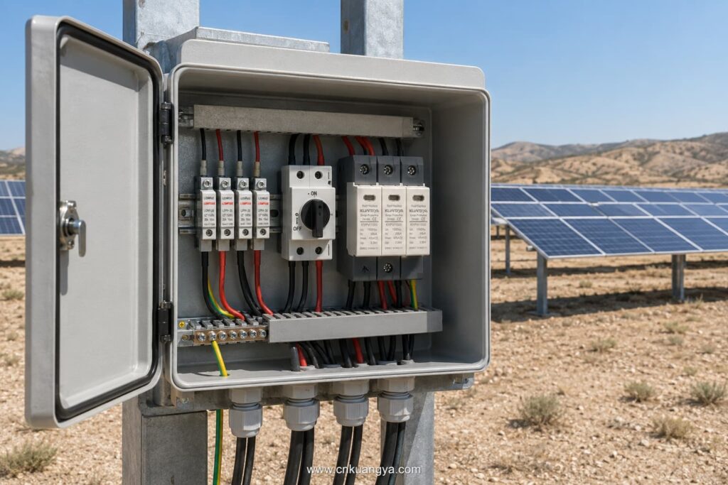
تنطبق التصنيفات المعلنة لأجهزة الحماية من زيادة التيار (SPD) في ظل ظروف التشغيل المذكورة في ورقة البيانات الخاصة بها. يجب مراعاة درجات الحرارة الداخلية المرتفعة داخل الخزانات، خاصة في الصناديق الخارجية المعرضة لأشعة الشمس المباشرة.
أجهزة الحماية من زيادة التيار (SPD) ليست مكونات دائمة ولا تحتاج إلى صيانة. يمكن أن تتدهور عناصر الحماية الخاصة بها بعد التعرض المتكرر لنوبات زيادة التيار.
تشمل ميزات الصيانة المفيدة ما يلي:
يجب فحص الوحدة وفقاً لخطة الصيانة وبعد حدوث نشاط صاعقي كبير أو وقوع حدث زيادة في الجهد معروف.
استبدل الوحدة في الحالات التالية:
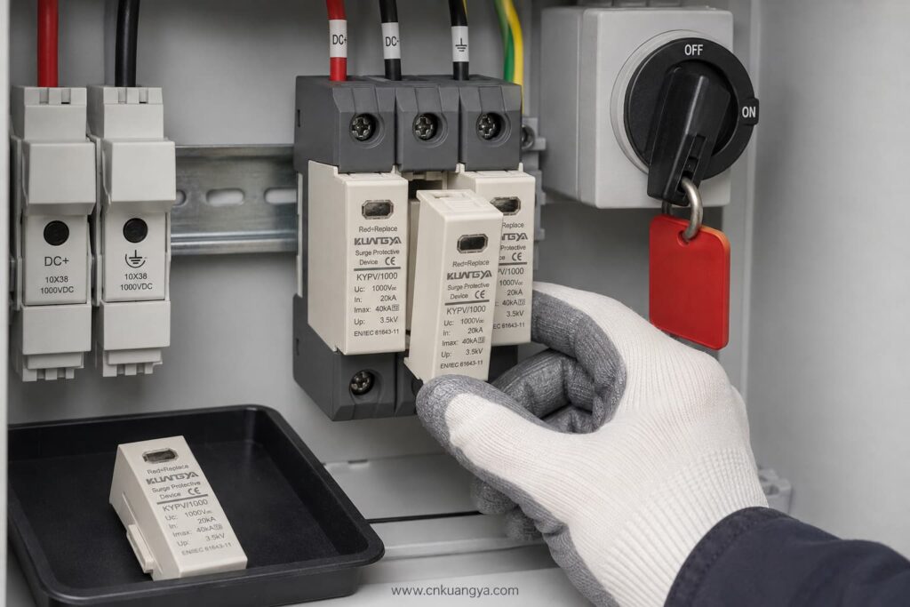
احرص دائماً على عزل دائرة التيار المستمر (DC) ذات الصلة واتباع إجراءات العمل الآمنة قبل الفحص أو الاستبدال.
| حالة المشروع | اختيار مانع الصواعق (SPD) للتقييم |
|---|---|
| أنظمة الطاقة الكهروضوئية (PV) على أسطح المباني السكنية التي لا يتوقع تعرضها لدخول تيارات الصواعق | جهاز حماية من اندفاع التيار المستمر (SPD) للأنظمة الكهروضوئية من النوع 2 |
| الأسطح التجارية ذات مسارات كابلات التيار المستمر الطويلة | أجهزة حماية من اندفاع التيار (SPDs) من النوع 2 منسقة في مواقع مناسبة |
| مبنى مزود بنظام حماية خارجي من الصواعق | النوع 1 أو النوع 1+2، اعتماداً على تصميم نظام الحماية من الصواعق |
| مصفوفة كهروضوئية على مستوى المرافق بجهد 1500 فولت | جهاز حماية من اندفاع التيار (SPD) مخصص للأنظمة الكهروضوئية بجهد 1500 فولت مع النوع المناسب وتصنيفات التفريغ |
| صندوق تجميع معرض للاندفاعات الكهربائية المستحثة | جهاز حماية من اندفاع التيار المستمر (SPD) للأنظمة الكهروضوئية من النوع 2 |
| العاكس الذي يتطلب حماية مدمجة من الصواعق والارتفاعات المفاجئة في التيار | جهاز حماية من اندفاع التيار (SPD) للتيار المستمر (PV DC) من النوع 1+2 إذا كان محدداً في التصميم |
هذا الجدول هو دليل أولي فقط. ولا يغني عن تقييم مخاطر المشروع أو عمل مصمم كهربائي معتمد.
توفير معلومات فنية كاملة يساعد المورد في اختيار المنتج الصحيح ويمنع التأخير.
أرسل التفاصيل التالية:
If the SPD type is not yet confirmed, provide the PV module data, number of modules per string, minimum design temperature, inverter model, system drawing, and lightning protection information.
Avoid these common errors:
Selecting a suitable جهاز الحماية من زيادة التيار المستمر (DC SPD) للمنشآت الشمسية في إسبانيا requires coordination between the PV system voltage, lightning risk, SPD classification, installation location, earthing arrangement, and applicable Spanish requirements.
The most important steps are:
KUANGYA supplies DC SPDs for solar PV applications in 600 V, 1,000 V, and 1,500 V configurations, including Type 2 and Type 1+2 options.
View the KUANGYA DC SPD range for photovoltaic systems or contact us with your system voltage, SPD type, discharge-current requirements, wiring configuration, quantity, and project location to request a data sheet and B2B quotation.
Not automatically. Type 2 is widely used for induced lightning and switching surges, but the final selection depends on the lightning protection system, risk assessment, equipment location, and project requirements.
Only if the SPD’s Ucpv is suitable for the maximum calculated PV voltage under the lowest expected temperature. Do not rely only on the nominal system description.
In is the nominal discharge current used to evaluate repeated Type 2 surge performance. Imax is the maximum 8/20 μs discharge current the SPD can withstand under specified test conditions.
It is used where the design requires both partial lightning-current discharge and Type 2 surge-limiting performance at the same installation point.
Common locations include the combiner box and inverter DC input. Long cable routes or exposed systems may require coordinated SPDs at more than one location.
UNE-EN 61643-31 is the principal Spanish standard covering requirements and test methods for SPDs used in photovoltaic installations. The complete installation must also follow the REBT and other applicable technical requirements.
If your project has already reached the stage of deciding between Type 1, Type 2 and Type 1+2 protection, continue with our detailed guide to Type 1 vs Type 2 SPD for solar PV in Spain.
This article provides general technical guidance. Final SPD selection and installation should be verified by the responsible project designer or an authorised electrical professional in accordance with current Spanish requirements.

