Zona industrial de WengYang Yueqing Wenzhou 325000
Horas de trabajo
De lunes a viernes: de 7.00 a 19.00 horas
Fin de semana: 10.00 A 17.00 HORAS
Zona industrial de WengYang Yueqing Wenzhou 325000
Horas de trabajo
De lunes a viernes: de 7.00 a 19.00 horas
Fin de semana: 10.00 A 17.00 HORAS

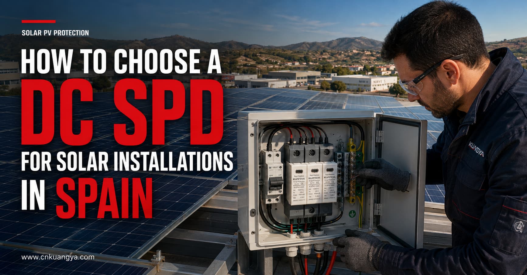
Los sistemas solares fotovoltaicos están expuestos a sobretensiones transitorias causadas por la actividad de rayos cercana, operaciones de conmutación y perturbaciones transmitidas a través de circuitos eléctricos conectados. Estos eventos pueden dañar inversores, equipos de monitorización, cajas de conexiones y otros componentes sensibles.
Elegir el SPD de CC correcto para instalaciones solares en España requiere algo más que hacer coincidir un dispositivo con la tensión nominal del sistema. Los diseñadores e instaladores también deben considerar la tensión máxima de circuito abierto fotovoltaico, la clasificación del SPD, la capacidad de descarga, el nivel de protección de tensión, la disposición de puesta a tierra del sistema, la distancia del cable, la ubicación de la instalación y las normas aplicables.
Sin embargo, elegir un SPD de CC implica algo más que hacer coincidir un dispositivo con una tensión nominal del sistema. Los diseñadores e instaladores también deben considerar la tensión máxima de circuito abierto fotovoltaico, la clasificación del SPD, la capacidad de descarga, el nivel de protección de tensión, la disposición de puesta a tierra del sistema, la distancia del cable, la ubicación de la instalación y las normas aplicables.
Esta guía explica cómo elegir un SPD de CC para instalaciones solares en España e identifica la información técnica que debe confirmarse antes de solicitar un presupuesto.
Los módulos fotovoltaicos y sus cables de conexión se instalan normalmente en áreas extensas y expuestas. Las rutas largas de cables de CC pueden actuar como vías a través de las cuales las sobretensiones transitorias inducidas por rayos y relacionadas con la conmutación llegan al inversor.
Una sobretensión no tiene por qué originarse necesariamente de un impacto directo de rayo en el conjunto fotovoltaico. Los rayos cercanos pueden inducir tensiones transitorias en los cables de CC, mientras que las operaciones de conmutación dentro de la instalación también pueden crear perturbaciones eléctricas.
Un SPD de CC está diseñado para:
Un SPD no sustituye a un fusible, interruptor automático, seccionador, sistema de puesta a tierra o sistema de protección externa contra el rayo. Cada dispositivo realiza una función de protección diferente y debe coordinarse como parte del diseño fotovoltaico completo.
Las instalaciones eléctricas de baja tensión en España se rigen por el Reglamento Electrotécnico para Baja Tensión, conocido comúnmente como REBT. El diseño aplicable también debe considerar las instrucciones técnicas vigentes, las especificaciones del proyecto, los requisitos locales y las normas referenciadas por el reglamento.
La lista oficial de normas asociadas al REBT en España incluye:
Para aplicaciones fotovoltaicas internacionales, también son importantes los siguientes documentos IEC:
La norma IEC 61643-31 se aplica a los SPD conectados al lado de CC de instalaciones fotovoltaicas con tensiones nominales de hasta 1.500 V CC.
Los requisitos del proyecto pueden variar según el tipo de instalación, la evaluación de riesgos, la ubicación, el diseño del inversor, el sistema de protección contra rayos externo y los requisitos de las autoridades españolas o del instalador autorizado. Por lo tanto, la selección del producto debe ser confirmada por el diseñador del proyecto o un profesional eléctrico cualificado.
El primer parámetro de selección es la tensión máxima de funcionamiento continuo del SPD para el sistema fotovoltaico, normalmente identificada como Ucpv.
No seleccione un SPD basándose únicamente en la tensión nominal de funcionamiento del inversor.
La tensión máxima de una cadena fotovoltaica depende de:
El voltaje del módulo fotovoltaico aumenta a medida que disminuye la temperatura. Por lo tanto, el voltaje de circuito abierto máximo en condiciones de frío de la cadena completa puede ser superior a su valor bajo condiciones de prueba estándar.
El Ucpv del SPD debe ser adecuado para el voltaje máximo que puede aparecer de forma continua a través del arreglo fotovoltaico.
| Sistema fotovoltaico | Clase de voltaje común del SPD | Verificación importante |
|---|---|---|
| Sistema fotovoltaico residencial pequeño | 600 V CC | Verificar la tensión de circuito abierto (Voc) máxima de la cadena en condiciones de frío |
| Fotovoltaica residencial o comercial | 1.000 V CC | Confirmar los límites de tensión del inversor y de la cadena (string) |
| Fotovoltaica comercial o a escala de servicio público | 1.500 V CC | Utilice un SPD diseñado específicamente para sistemas fotovoltaicos de 1.500 V |
Estos son ejemplos de aplicación, no reglas de selección automática. La tensión final del SPD debe basarse en la tensión fotovoltaica máxima calculada y en el esquema de conexión del fabricante.
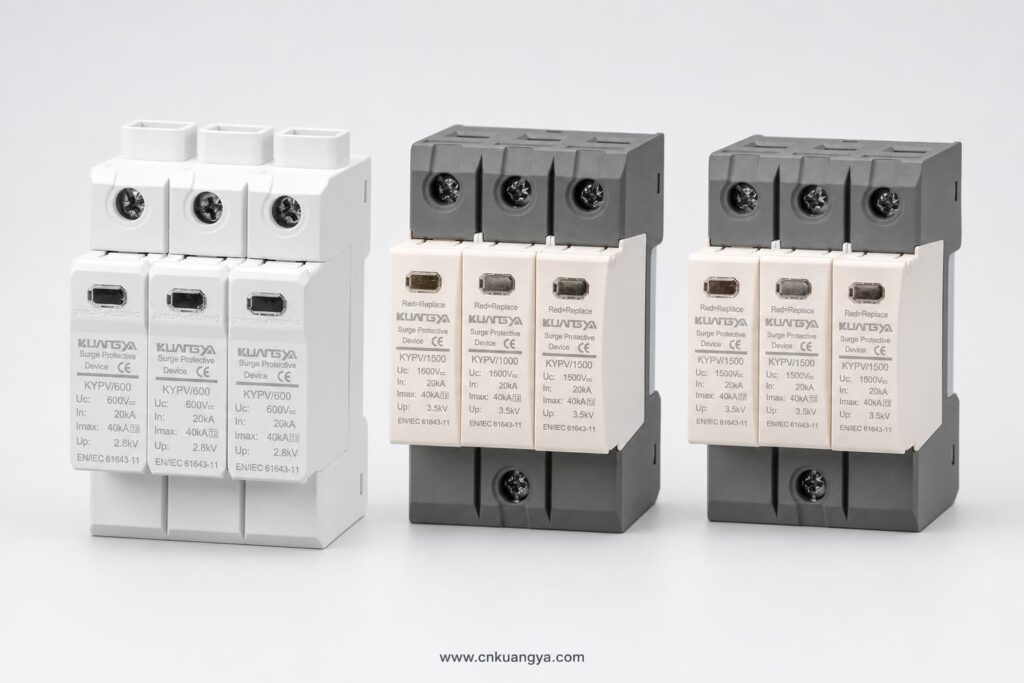
Seleccionar un SPD con una Ucpv insuficiente puede provocar un funcionamiento prematuro, sobrecalentamiento o desconexión. Seleccionar una tensión nominal innecesariamente más alta de lo requerido puede resultar en un nivel de protección de tensión más elevado y una protección menos eficaz para los equipos sensibles.
Los SPD para sistemas fotovoltaicos se clasifican normalmente según la corriente de descarga que están diseñados para soportar.
Un SPD de Tipo 2 se utiliza habitualmente para proteger contra sobretensiones inducidas por rayos y sobretensiones de maniobra.
Las aplicaciones típicas son:
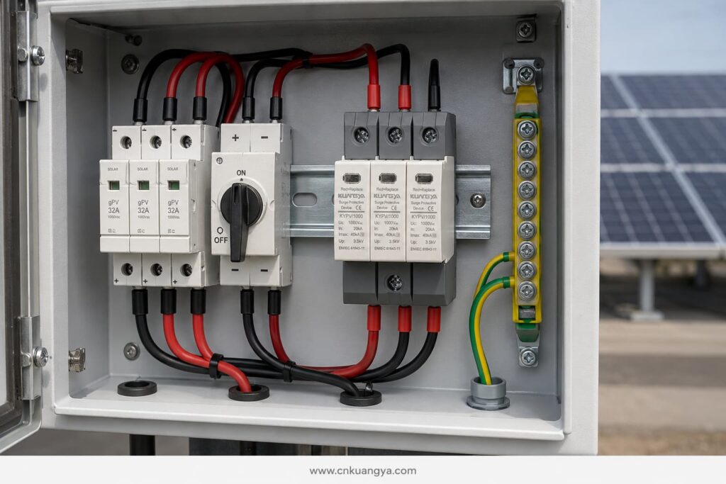
Los dispositivos Tipo 2 se especifican normalmente utilizando la corriente de descarga nominal En y la corriente de descarga máxima Imax, basadas en una forma de onda de corriente de 8/20 μs.
Un SPD Tipo 1 está diseñado para descargar corriente de rayo parcial. Puede ser necesario cuando el diseño de protección contra rayos indica que la corriente de rayo puede ingresar a la instalación eléctrica.
La selección del Tipo 1 se asocia típicamente con:
La capacidad de Tipo 1 se expresa normalmente utilizando la corriente de descarga de impulso Iimp, basada en una forma de onda de 10/350 μs.
Un SPD de Tipo 1+2 combina la protección contra corrientes de rayo y sobretensiones inducidas en un solo dispositivo.
Puede considerarse para:
El tipo de SPD debe seleccionarse de acuerdo con el concepto de protección contra rayos del proyecto. No debe elegirse solo porque un número de tipo más alto parezca más potente.
Las diferentes clasificaciones de SPD describen diferentes aspectos del rendimiento.
En indica la corriente que un SPD de Tipo 2 puede descargar repetidamente bajo las condiciones de prueba especificadas, normalmente utilizando una forma de onda de 8/20 μs.
Es uno de los valores nominales principales utilizados al comparar SPD de Tipo 2.
Imax es la corriente de descarga máxima de 8/20 μs que el SPD puede manejar bajo sus condiciones de prueba especificadas.
Un valor nominal de Imax alto por sí solo no demuestra que un SPD sea adecuado para una instalación en particular. Debe considerarse junto con In, Up, Ucpv, el comportamiento ante cortocircuitos, la disposición de la conexión y la norma de prueba aplicable.
Iimp se utiliza para dispositivos de Tipo 1 y Tipo 1+2 y representa la capacidad de corriente de impulso de rayo utilizando una forma de onda de 10/350 μs.
Cuando se requiera protección de Tipo 1, compare el valor de Iimp por polo o modo de protección de acuerdo con la especificación del proyecto.
Arriba indica la tensión residual que aparece en los bornes del SPD durante la prueba de descarga especificada.
The Up value should be lower than the impulse withstand level of the equipment being protected. Connection cables also add voltage during a surge, so the effective protection level at the inverter can be higher than the SPD’s catalogue value.
This is why short, direct SPD connections are essential.
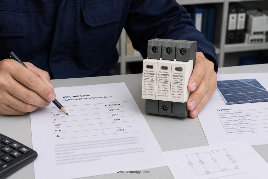
A PV DC circuit may be floating, functionally earthed, or configured according to a specific inverter topology. The SPD must use a connection arrangement suitable for that system.
Before selecting the number of poles or protection modes, confirm:
Do not assume that an AC SPD with a similar voltage can be used on the PV DC side. PV systems have specific continuous-voltage and fault-current characteristics. The device should be designed and tested for photovoltaic DC applications according to IEC/UNE-EN 61643-31.
A PV SPD must be able to disconnect safely if it reaches the end of its service life.
Important parameters include:
The external backup fuse should not be selected only according to the SPD’s physical size. Follow the SPD manufacturer’s data sheet and verify compatibility with the PV string current and the system’s fault characteristics.
The SPD protects against transient overvoltage. The gPV fuse or DC breaker protects against overcurrent and short-circuit conditions. One device cannot replace the other.
Typical DC SPD locations include:
The most suitable arrangement depends on cable length, exposure, lightning protection design, equipment withstand level, and project risk assessment.
For a compact rooftop installation with short DC cable routes, a Type 2 SPD near the inverter may provide the required protection when permitted by the design.
For longer routes between the PV array and inverter, coordinated SPDs may be required at both ends. This reduces the voltage stress that can develop along the cable and improves protection for equipment at each location.
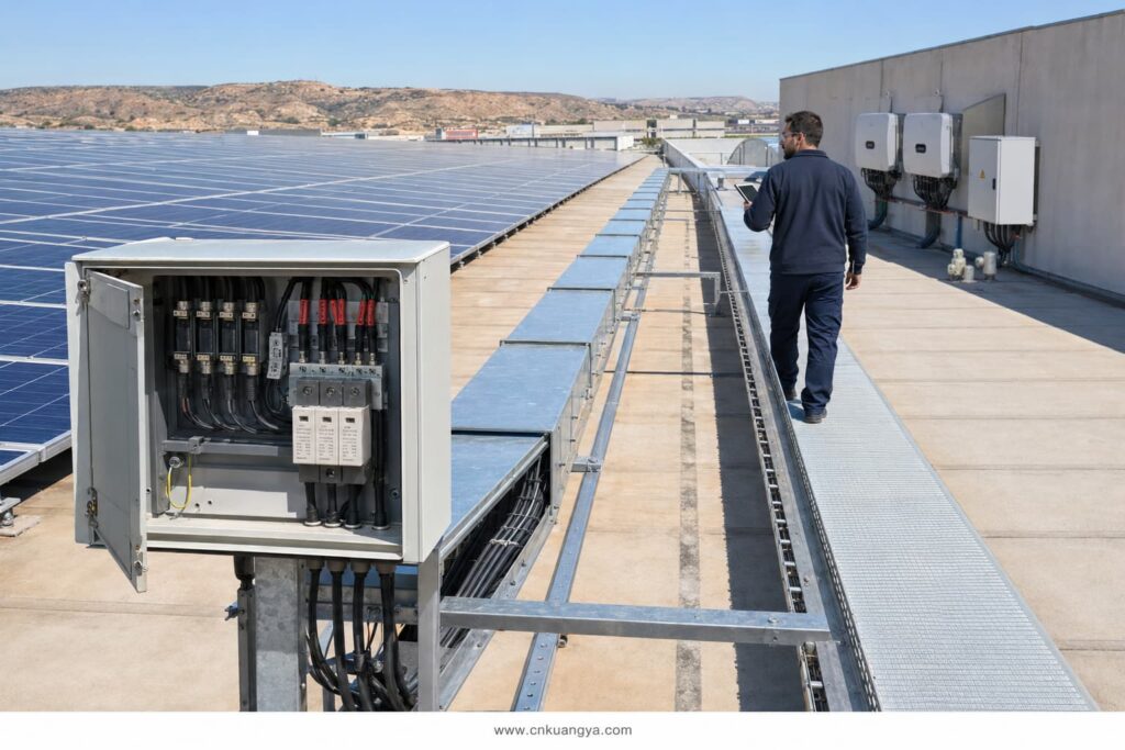
Some industry design guidance uses approximately 10 metres as a point at which additional coordination should be considered. This should not be treated as a universal rule for every Spanish installation. The final placement must follow the applicable design standard, risk assessment, cable routing, and equipment manufacturer’s instructions.
Even a correctly rated SPD can provide poor protection if it is installed with long or badly routed cables.
During a surge, cable inductance creates additional voltage. Longer conductors can therefore increase the total voltage reaching the inverter.
Good installation practice includes:
The objective is to reduce the total connection length and minimise the effective protection level at the protected equipment.
DIN-rail SPD modules do not automatically provide outdoor protection. Their environmental protection depends on the enclosure in which they are installed.
For rooftop and outdoor PV systems in Spain, check:
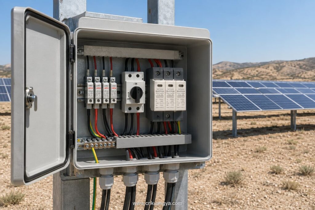
The SPD’s declared ratings apply under the operating conditions stated in its data sheet. High internal cabinet temperatures should be considered, especially in outdoor enclosures exposed to direct sunlight.
SPDs are not permanent, maintenance-free components. Their protective elements can deteriorate after repeated surge events.
Useful maintenance features include:
The module should be inspected according to the maintenance plan and after significant lightning activity or a known surge event.
Replace the module when:
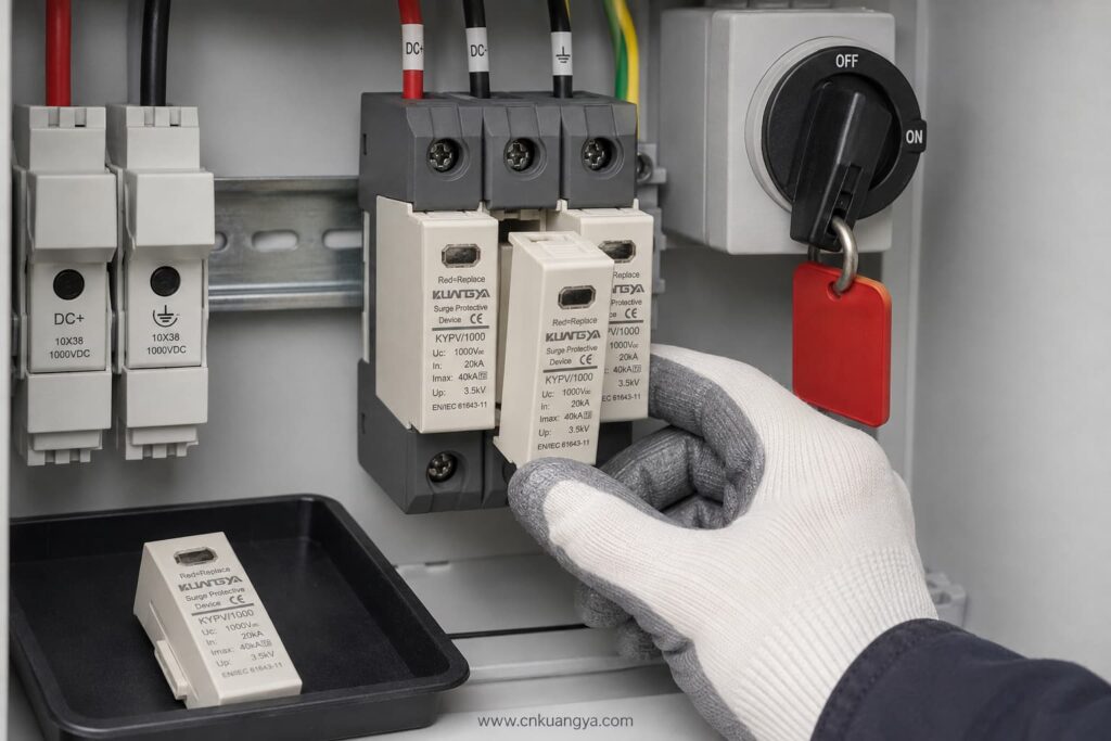
Always isolate the relevant DC circuit and follow safe working procedures before inspection or replacement.
| Project Condition | SPD Selection to Evaluate |
|---|---|
| Residential rooftop PV without expected lightning-current entry | Type 2 PV DC SPD |
| Commercial rooftop with long DC cable routes | Coordinated Type 2 SPDs at suitable locations |
| Building with an external lightning protection system | Type 1 or Type 1+2, depending on the lightning protection design |
| Utility-scale 1,500 V PV array | PV-specific 1,500 V SPD with suitable Type and discharge ratings |
| Combiner box exposed to induced surges | Type 2 PV DC SPD |
| Inverter requiring combined lightning and surge protection | Type 1+2 PV DC SPD if specified by the design |
This table is a preliminary guide only. It does not replace the project risk assessment or the work of an authorised electrical designer.
Providing complete technical information helps the supplier select the correct product and prevents delays.
Send the following details:
If the SPD type is not yet confirmed, provide the PV module data, number of modules per string, minimum design temperature, inverter model, system drawing, and lightning protection information.
Avoid these common errors:
Selecting a suitable SPD de CC correcto para instalaciones solares en España requires coordination between the PV system voltage, lightning risk, SPD classification, installation location, earthing arrangement, and applicable Spanish requirements.
The most important steps are:
KUANGYA supplies DC SPDs for solar PV applications in 600 V, 1,000 V, and 1,500 V configurations, including Type 2 and Type 1+2 options.
View the KUANGYA DC SPD range for photovoltaic systems or contact us with your system voltage, SPD type, discharge-current requirements, wiring configuration, quantity, and project location to request a data sheet and B2B quotation.
Not automatically. Type 2 is widely used for induced lightning and switching surges, but the final selection depends on the lightning protection system, risk assessment, equipment location, and project requirements.
Only if the SPD’s Ucpv is suitable for the maximum calculated PV voltage under the lowest expected temperature. Do not rely only on the nominal system description.
In is the nominal discharge current used to evaluate repeated Type 2 surge performance. Imax is the maximum 8/20 μs discharge current the SPD can withstand under specified test conditions.
It is used where the design requires both partial lightning-current discharge and Type 2 surge-limiting performance at the same installation point.
Common locations include the combiner box and inverter DC input. Long cable routes or exposed systems may require coordinated SPDs at more than one location.
UNE-EN 61643-31 is the principal Spanish standard covering requirements and test methods for SPDs used in photovoltaic installations. The complete installation must also follow the REBT and other applicable technical requirements.
If your project has already reached the stage of deciding between Type 1, Type 2 and Type 1+2 protection, continue with our detailed guide to Type 1 vs Type 2 SPD for solar PV in Spain.
This article provides general technical guidance. Final SPD selection and installation should be verified by the responsible project designer or an authorised electrical professional in accordance with current Spanish requirements.

