Промышленная зона Вэньян Юэцин Вэньчжоу 325000
Рабочие часы
Понедельник - пятница: 7AM - 7PM
Выходные: 10AM - 5PM
Промышленная зона Вэньян Юэцин Вэньчжоу 325000
Рабочие часы
Понедельник - пятница: 7AM - 7PM
Выходные: 10AM - 5PM

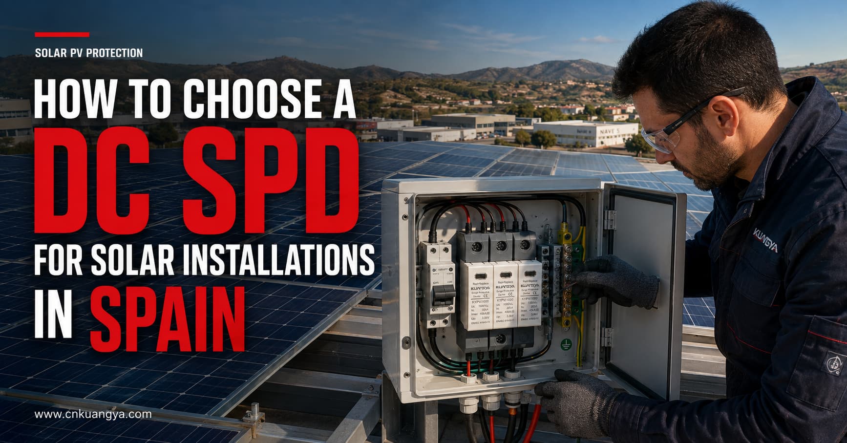
Солнечные фотоэлектрические системы подвержены воздействию переходных перенапряжений, вызванных близкими ударами молнии, коммутационными операциями и помехами, передаваемыми через подключенные электрические цепи. Эти явления могут привести к повреждению инверторов, оборудования мониторинга, сумматорных коробок и других чувствительных компонентов.
Выбор подходящего УЗИП постоянного тока для солнечных установок в Испании требует не только соответствия устройства номинальному напряжению системы. Проектировщики и монтажники также должны учитывать максимальное напряжение холостого хода фотоэлектрической системы, классификацию УЗИП, разрядную способность, уровень напряжения защиты, схему заземления системы, длину кабеля, место установки и применимые стандарты.
Однако выбор УЗИП постоянного тока включает в себя нечто большее, чем просто соответствие устройства номинальному напряжению системы. Проектировщики и монтажники также должны учитывать максимальное напряжение холостого хода фотоэлектрической системы, классификацию УЗИП, разрядную способность, уровень напряжения защиты, схему заземления системы, длину кабеля, место установки и применимые стандарты.
В данном руководстве объясняется, как выбрать УЗИП постоянного тока для солнечных установок в Испании, а также указана техническая информация, которую необходимо подтвердить перед запросом коммерческого предложения.
Фотоэлектрические модули и соединительные кабели обычно устанавливаются на больших открытых площадях. Длинные кабельные трассы постоянного тока могут служить путями, по которым индуцированные молнией и связанные с коммутацией переходные перенапряжения достигают инвертора.
Импульс перенапряжения не обязательно должен быть вызван прямым ударом молнии в фотоэлектрическую установку. Близкие разряды молнии могут индуцировать переходные напряжения в кабелях постоянного тока, в то время как коммутационные операции внутри установки также могут создавать электрические помехи.
УЗИП постоянного тока предназначено для:
УЗИП не заменяет предохранитель, автоматический выключатель, разъединитель, систему заземления или систему внешней молниезащиты. Каждое устройство выполняет свою защитную функцию и должно быть скоординировано в рамках комплексного проекта фотоэлектрической системы.
Низковольтные электроустановки в Испании регулируются «Электротехническим регламентом для низкого напряжения» (Reglamento Electrotécnico para Baja Tensión), широко известным как REBT. Применяемый проект также должен учитывать действующие технические инструкции, спецификации проекта, местные требования и стандарты, на которые ссылается регламент.
Официальный перечень стандартов Испании, связанных с REBT, включает:
Для международных фотоэлектрических систем также важны следующие документы МЭК (IEC):
Стандарт IEC 61643-31 применяется к устройствам защиты от перенапряжений (УЗИП), подключаемым к стороне постоянного тока фотоэлектрических установок с номинальным напряжением до 1500 В постоянного тока.
Требования к проекту могут различаться в зависимости от типа установки, оценки рисков, местоположения, конструкции инвертора, внешней системы молниезащиты, а также требований испанских органов власти или уполномоченного монтажника. Поэтому выбор продукции должен быть подтвержден проектировщиком или квалифицированным специалистом-электриком.
Первым параметром выбора является максимальное длительное рабочее напряжение УЗИП для фотоэлектрической системы, обычно обозначаемое как Ucpv.
Не выбирайте УЗИП, основываясь только на номинальном рабочем напряжении инвертора.
Максимальное напряжение фотоэлектрической цепочки зависит от:
Напряжение фотоэлектрического модуля возрастает при понижении температуры. Следовательно, максимальное напряжение холостого хода всей цепочки в холодных условиях может быть выше, чем его значение при стандартных условиях испытаний.
Параметр Ucpv устройства защиты от импульсных перенапряжений (УЗИП) должен соответствовать максимальному напряжению, которое может постоянно присутствовать на фотоэлектрической матрице.
| Фотоэлектрическая система | Стандартный класс напряжения УЗИП | Важная проверка |
|---|---|---|
| Малая бытовая фотоэлектрическая система | 600 В ПОСТОЯННОГО ТОКА | Проверка максимального напряжения холостого хода (Voc) стринга в холодном состоянии |
| Жилые или коммерческие фотоэлектрические системы | 1000 В пост. тока | Проверьте предельные значения напряжения инвертора и стринга |
| Коммерческие или промышленные фотоэлектрические системы | 1500 В пост. тока | Используйте УЗИП, специально разработанное для фотоэлектрических систем с напряжением 1500 В |
Это примеры применения, а не правила автоматического выбора. Конечное напряжение УЗИП должно основываться на расчетном максимальном напряжении фотоэлектрической системы и схеме подключения производителя.
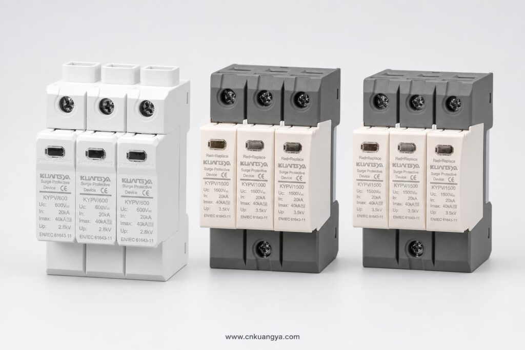
Выбор УЗИП с недостаточным значением Ucpv может привести к преждевременному срабатыванию, перегреву или отключению. Выбор номинального напряжения, неоправданно превышающего требуемое, может привести к повышению уровня защиты по напряжению и снижению эффективности защиты чувствительного оборудования.
УЗИП для фотоэлектрических систем обычно классифицируются в соответствии с импульсным током, на который они рассчитаны.
УЗИП типа 2 обычно используются для защиты от наведенных грозовых перенапряжений и коммутационных перенапряжений.
Типичные области применения включают:
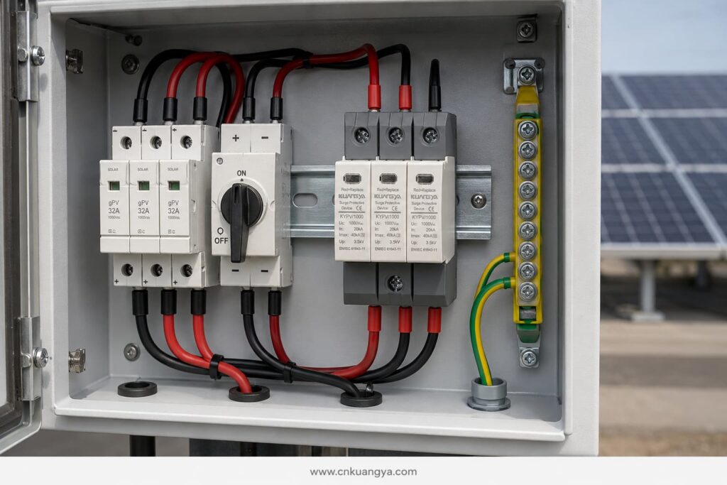
Устройства типа 2 обычно характеризуются номинальным разрядным током На сайте и максимальным разрядным током Imax, основанными на форме волны тока 8/20 мкс.
УЗИП типа 1 предназначено для отвода части тока молнии. Оно может потребоваться в случаях, когда проект молниезащиты указывает на возможность попадания тока молнии в электроустановку.
Выбор типа 1 обычно связан с:
Характеристики УЗИП типа 1 обычно выражаются через импульсный ток разряда Iimp, основанный на форме волны 10/350 мкс.
УЗИП типа 1+2 объединяет в одном устройстве защиту от токов молнии и наведенных перенапряжений.
Может рассматриваться для:
Тип УЗИП должен выбираться в соответствии с концепцией молниезащиты проекта. Его не следует выбирать только потому, что более высокий номер типа кажется более мощным.
Различные номинальные параметры УЗИП описывают разные аспекты производительности.
На сайте указывает ток, который УЗИП типа 2 может многократно отводить при заданных условиях испытаний, обычно с использованием формы волны 8/20 мкс.
Это один из основных номинальных параметров, используемых при сравнении УЗИП типа 2.
Imax это максимальный разрядный ток с формой волны 8/20 мкс, который УЗИП может выдержать при заданных условиях испытаний.
Высокое значение Imax само по себе не доказывает, что УЗИП подходит для конкретной установки. Его необходимо рассматривать в совокупности с In, Up, Ucpv, поведением при коротком замыкании, схемой подключения и применимым стандартом испытаний.
Iimp используется для устройств типа 1 и типа 1+2 и представляет собой способность выдерживать ток молниевого импульса с формой волны 10/350 мкс.
При необходимости защиты типа 1 сравните значение Iimp на полюс или режим защиты в соответствии со спецификацией проекта.
Вверх указывает остаточное напряжение, возникающее на УЗИП во время заданного испытания на разряд.
Уровень Up должен быть ниже уровня импульсного выдерживаемого напряжения защищаемого оборудования. Соединительные кабели также добавляют напряжение во время скачка, поэтому эффективный уровень защиты на инверторе может быть выше, чем значение, указанное в каталоге УЗИП.
Именно поэтому крайне важны короткие и прямые подключения УЗИП.
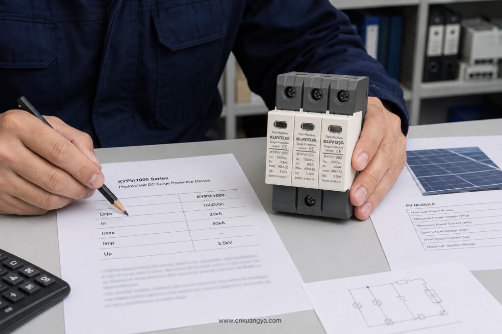
Цепь постоянного тока фотоэлектрической системы может быть изолированной, функционально заземленной или сконфигурированной в соответствии с конкретной топологией инвертора. УЗИП должен использовать схему подключения, подходящую для данной системы.
Перед выбором количества полюсов или режимов защиты подтвердите:
Не следует полагать, что УЗИП переменного тока с аналогичным напряжением можно использовать на стороне постоянного тока фотоэлектрической системы. Фотоэлектрические системы имеют специфические характеристики постоянного напряжения и токов повреждения. Устройство должно быть спроектировано и испытано для применения в фотоэлектрических системах постоянного тока в соответствии со стандартом IEC/UNE-EN 61643-31.
УЗИП для фотоэлектрических систем должно безопасно отключаться по истечении срока службы.
Важные параметры включают:
Внешний резервный предохранитель не должен выбираться только на основе физических размеров УЗИП. Следуйте техническому паспорту производителя УЗИП и проверьте совместимость с током фотоэлектрической цепи и характеристиками неисправностей системы.
УЗИП защищает от переходных перенапряжений. Предохранитель gPV или автоматический выключатель постоянного тока защищает от перегрузки по току и короткого замыкания. Одно устройство не может заменить другое.
Типичные места установки УЗИП постоянного тока включают:
Наиболее подходящая схема зависит от длины кабеля, условий эксплуатации, проекта молниезащиты, уровня устойчивости оборудования к перенапряжениям и оценки проектных рисков.
Для компактных крышных установок с короткими трассами кабелей постоянного тока, УЗИП типа 2, установленное рядом с инвертором, может обеспечить необходимый уровень защиты, если это допускается проектом.
Для более длинных трасс между фотоэлектрическим массивом и инвертором может потребоваться установка согласованных УЗИП на обоих концах. Это снижает напряжение, которое может возникнуть вдоль кабеля, и улучшает защиту оборудования в каждой точке.
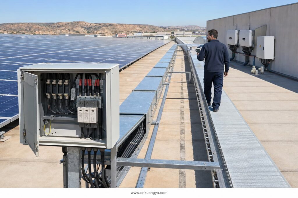
В некоторых отраслевых руководствах по проектированию расстояние около 10 метров используется как точка, при которой следует рассмотреть дополнительное согласование. Это не должно рассматриваться как универсальное правило для каждой установки в Испании. Окончательное размещение должно соответствовать применимым стандартам проектирования, оценке рисков, прокладке кабелей и инструкциям производителя оборудования.
Даже правильно подобранное УЗИП может обеспечить низкий уровень защиты, если оно установлено с использованием длинных или неправильно проложенных кабелей.
Во время скачка напряжения индуктивность кабеля создает дополнительное напряжение. Таким образом, более длинные проводники могут увеличить общее напряжение, достигающее инвертора.
Правила качественного монтажа включают:
Цель состоит в том, чтобы сократить общую длину соединений и минимизировать эффективный уровень защиты оборудования.
DIN-rail SPD modules do not automatically provide outdoor protection. Their environmental protection depends on the enclosure in which they are installed.
For rooftop and outdoor PV systems in Spain, check:
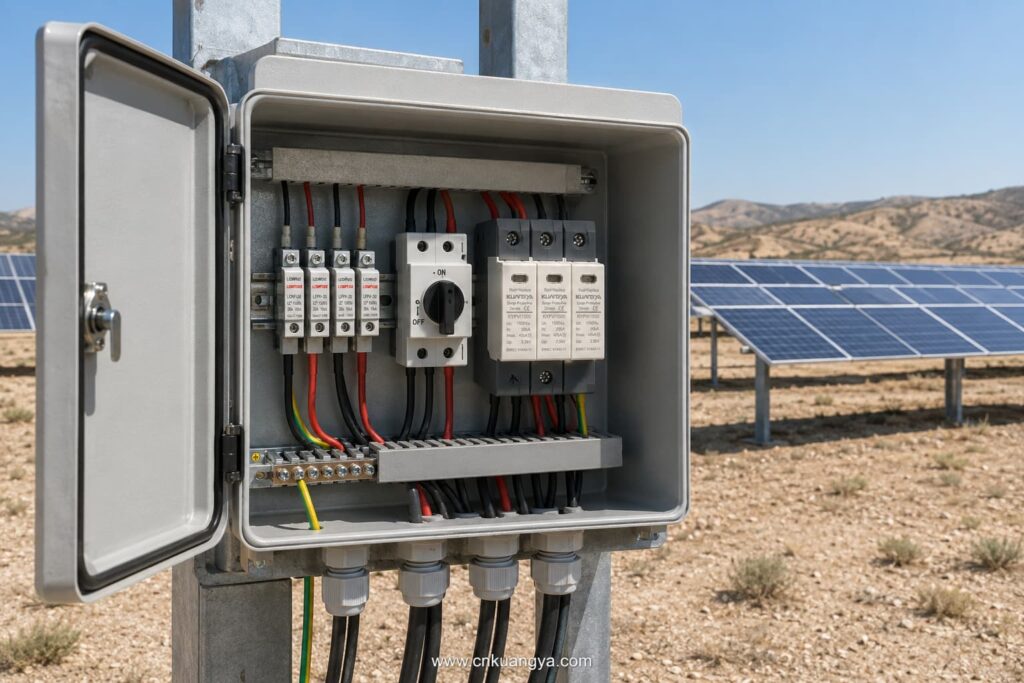
The SPD’s declared ratings apply under the operating conditions stated in its data sheet. High internal cabinet temperatures should be considered, especially in outdoor enclosures exposed to direct sunlight.
SPDs are not permanent, maintenance-free components. Their protective elements can deteriorate after repeated surge events.
Useful maintenance features include:
The module should be inspected according to the maintenance plan and after significant lightning activity or a known surge event.
Replace the module when:
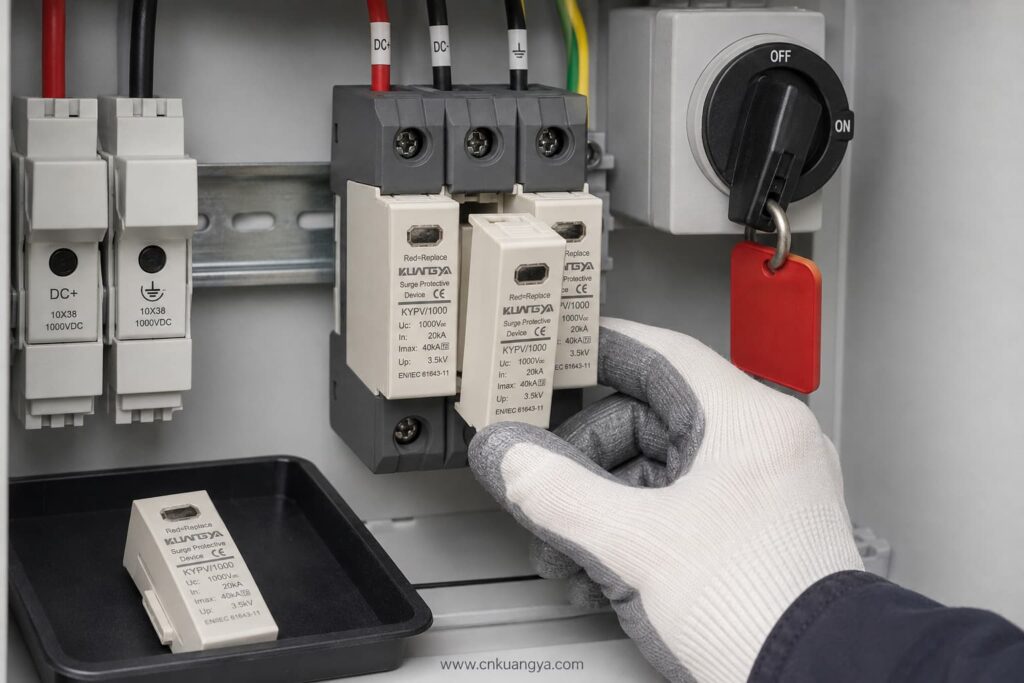
Always isolate the relevant DC circuit and follow safe working procedures before inspection or replacement.
| Project Condition | SPD Selection to Evaluate |
|---|---|
| Residential rooftop PV without expected lightning-current entry | Type 2 PV DC SPD |
| Commercial rooftop with long DC cable routes | Coordinated Type 2 SPDs at suitable locations |
| Building with an external lightning protection system | Type 1 or Type 1+2, depending on the lightning protection design |
| Utility-scale 1,500 V PV array | PV-specific 1,500 V SPD with suitable Type and discharge ratings |
| Combiner box exposed to induced surges | Type 2 PV DC SPD |
| Inverter requiring combined lightning and surge protection | Type 1+2 PV DC SPD if specified by the design |
This table is a preliminary guide only. It does not replace the project risk assessment or the work of an authorised electrical designer.
Providing complete technical information helps the supplier select the correct product and prevents delays.
Send the following details:
If the SPD type is not yet confirmed, provide the PV module data, number of modules per string, minimum design temperature, inverter model, system drawing, and lightning protection information.
Avoid these common errors:
Selecting a suitable УЗИП постоянного тока для солнечных установок в Испании requires coordination between the PV system voltage, lightning risk, SPD classification, installation location, earthing arrangement, and applicable Spanish requirements.
The most important steps are:
KUANGYA supplies DC SPDs for solar PV applications in 600 V, 1,000 V, and 1,500 V configurations, including Type 2 and Type 1+2 options.
View the KUANGYA DC SPD range for photovoltaic systems or contact us with your system voltage, SPD type, discharge-current requirements, wiring configuration, quantity, and project location to request a data sheet and B2B quotation.
Not automatically. Type 2 is widely used for induced lightning and switching surges, but the final selection depends on the lightning protection system, risk assessment, equipment location, and project requirements.
Only if the SPD’s Ucpv is suitable for the maximum calculated PV voltage under the lowest expected temperature. Do not rely only on the nominal system description.
In is the nominal discharge current used to evaluate repeated Type 2 surge performance. Imax is the maximum 8/20 μs discharge current the SPD can withstand under specified test conditions.
It is used where the design requires both partial lightning-current discharge and Type 2 surge-limiting performance at the same installation point.
Common locations include the combiner box and inverter DC input. Long cable routes or exposed systems may require coordinated SPDs at more than one location.
UNE-EN 61643-31 is the principal Spanish standard covering requirements and test methods for SPDs used in photovoltaic installations. The complete installation must also follow the REBT and other applicable technical requirements.
If your project has already reached the stage of deciding between Type 1, Type 2 and Type 1+2 protection, continue with our detailed guide to Type 1 vs Type 2 SPD for solar PV in Spain.
This article provides general technical guidance. Final SPD selection and installation should be verified by the responsible project designer or an authorised electrical professional in accordance with current Spanish requirements.

