Zona industriale di WengYang Yueqing Wenzhou 325000
Orario di lavoro
Da lunedì a venerdì: dalle 7.00 alle 19.00
Fine settimana: 10.00 - 17.00
Zona industriale di WengYang Yueqing Wenzhou 325000
Orario di lavoro
Da lunedì a venerdì: dalle 7.00 alle 19.00
Fine settimana: 10.00 - 17.00

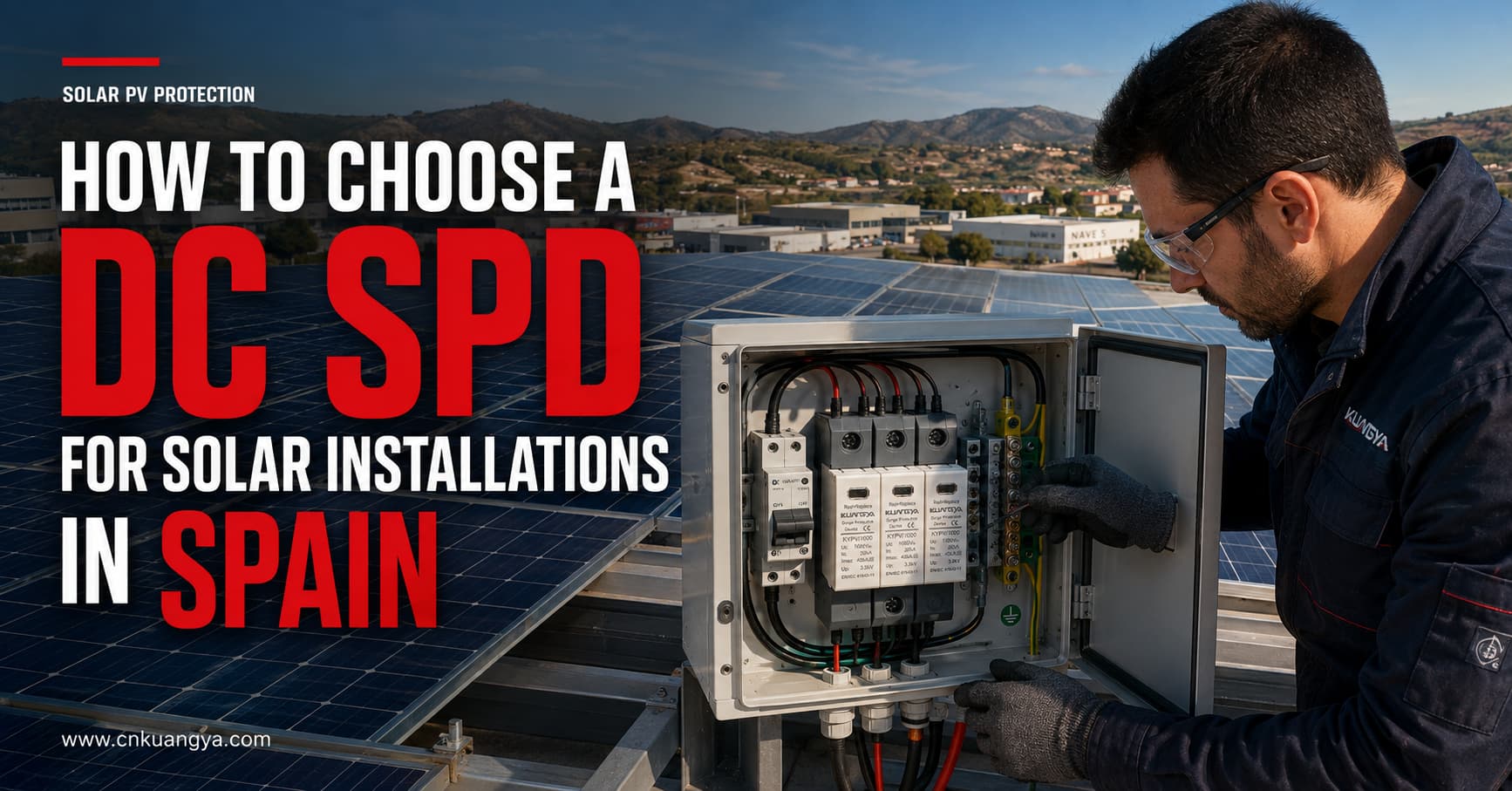
Gli impianti solari fotovoltaici sono esposti a sovratensioni transitorie causate da attività fulminante nelle vicinanze, operazioni di commutazione e disturbi trasmessi attraverso i circuiti elettrici collegati. Questi eventi possono danneggiare inverter, apparecchiature di monitoraggio, quadri di parallelo (combiner box) e altri componenti sensibili.
La scelta del corretto SPD CC per impianti solari in Spagna richiede molto più del semplice abbinamento di un dispositivo alla tensione nominale del sistema. Progettisti e installatori devono considerare anche la tensione massima a circuito aperto del fotovoltaico, la classificazione dell'SPD, la capacità di scarica, il livello di protezione dalla tensione, il sistema di messa a terra, la lunghezza dei cavi, il luogo di installazione e le normative applicabili.
Tuttavia, la scelta di un SPD CC comporta molto più del semplice abbinamento di un dispositivo alla tensione nominale del sistema. Progettisti e installatori devono considerare anche la tensione massima a circuito aperto del fotovoltaico, la classificazione dell'SPD, la capacità di scarica, il livello di protezione dalla tensione, il sistema di messa a terra, la lunghezza dei cavi, il luogo di installazione e le normative applicabili.
Questa guida spiega come scegliere un SPD CC per impianti solari in Spagna e identifica le informazioni tecniche da confermare prima di richiedere un preventivo.
I moduli fotovoltaici e i relativi cavi di collegamento sono solitamente installati su ampie aree esposte. I lunghi percorsi dei cavi in DC possono fungere da vie attraverso le quali le sovratensioni transitorie, indotte da fulmini o causate da manovre di commutazione, raggiungono l'inverter.
Una sovratensione non deve necessariamente originarsi da un fulmine che colpisce direttamente l'impianto fotovoltaico. Fulmini nelle vicinanze possono indurre tensioni transitorie nei cavi DC, mentre le operazioni di commutazione all'interno dell'impianto possono anch'esse creare disturbi elettrici.
Un dispositivo di protezione contro le sovratensioni (SPD) in DC è progettato per:
Un SPD non sostituisce un fusibile, un interruttore automatico, un sezionatore, un sistema di messa a terra o un sistema di protezione contro i fulmini esterno. Ogni dispositivo svolge una diversa funzione di protezione e deve essere coordinato come parte integrante del progetto fotovoltaico completo.
Gli impianti elettrici a bassa tensione in Spagna sono regolati dal Reglamento Electrotécnico para Baja Tensión, comunemente noto come REBT. Il progetto applicabile deve inoltre considerare le istruzioni tecniche vigenti, le specifiche di progetto, i requisiti locali e gli standard richiamati dal regolamento.
L'elenco ufficiale spagnolo degli standard associati al REBT include:
Per le applicazioni fotovoltaiche internazionali, sono importanti anche i seguenti documenti IEC:
La norma IEC 61643-31 si applica agli SPD collegati al lato CC di impianti fotovoltaici con tensioni nominali fino a 1.500 V CC.
I requisiti del progetto possono variare in base al tipo di installazione, alla valutazione del rischio, all'ubicazione, al design dell'inverter, al sistema di protezione contro i fulmini esterno e ai requisiti delle autorità spagnole o dell'installatore autorizzato. La scelta del prodotto deve pertanto essere confermata dal progettista o da un professionista elettrico qualificato.
Il primo parametro di selezione è la tensione massima di funzionamento continuo dell'SPD per il sistema fotovoltaico, normalmente identificata come Ucpv.
Non selezionare un SPD basandosi esclusivamente sulla tensione operativa nominale dell'inverter.
La tensione massima di una stringa fotovoltaica dipende da:
La tensione del modulo fotovoltaico aumenta al diminuire della temperatura. Pertanto, la tensione a circuito aperto massima in condizioni di freddo dell'intera stringa può essere superiore al suo valore in condizioni di prova standard.
La Ucpv dello scaricatore di sovratensioni (SPD) deve essere idonea alla tensione massima che può presentarsi in modo continuo ai capi dell'impianto fotovoltaico.
| Impianto fotovoltaico | Classe di tensione SPD comune | Verifica importante |
|---|---|---|
| Piccolo impianto fotovoltaico residenziale | 600 V CC | Verificare la tensione a circuito aperto (Voc) massima della stringa in condizioni di freddo |
| Fotovoltaico residenziale o commerciale | 1.000 V DC | Verificare i limiti di tensione dell'inverter e delle stringhe |
| Fotovoltaico commerciale o su scala industriale | 1.500 V DC | Utilizzare un SPD specificamente progettato per sistemi fotovoltaici a 1.500 V |
Questi sono esempi di applicazione, non regole di selezione automatica. La tensione finale dell'SPD deve basarsi sulla tensione fotovoltaica massima calcolata e sullo schema di collegamento del produttore.
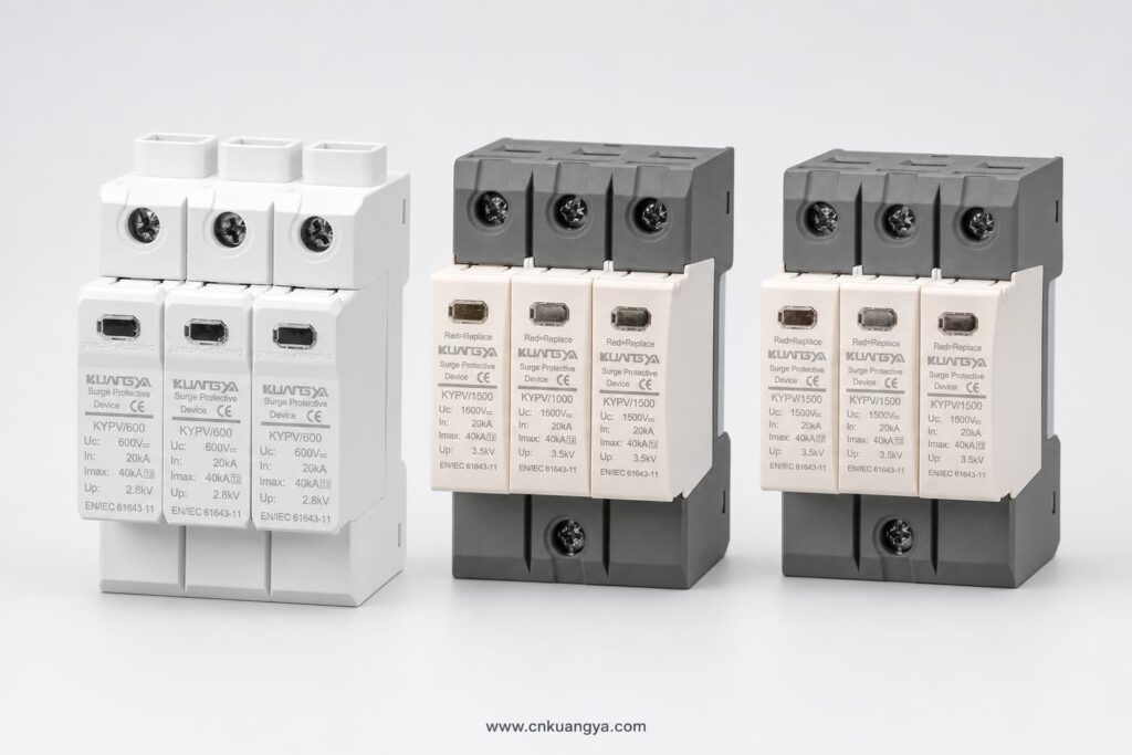
La selezione di un SPD con una Ucpv insufficiente può causare un funzionamento prematuro, surriscaldamento o disconnessione. La selezione di una tensione nominale inutilmente superiore a quella richiesta può comportare un livello di protezione dalla tensione più elevato e una protezione meno efficace per le apparecchiature sensibili.
Gli SPD per impianti fotovoltaici sono solitamente classificati in base alla corrente di scarica che sono progettati per gestire.
Un SPD di Tipo 2 viene comunemente utilizzato per proteggere da sovratensioni indotte da fulmini e sovratensioni di manovra.
Le applicazioni tipiche includono:
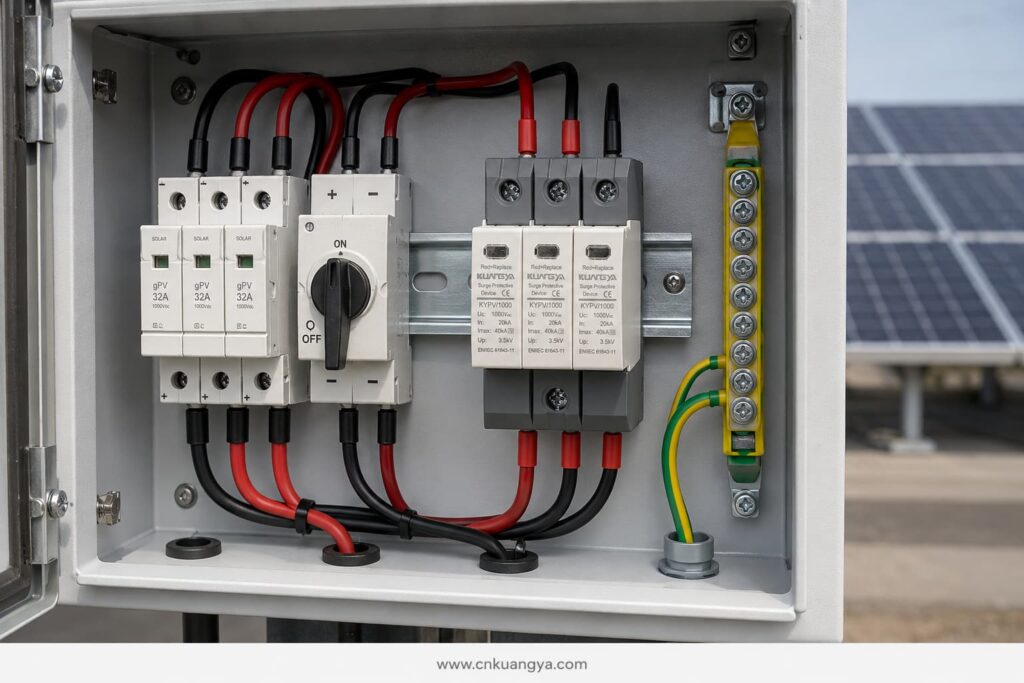
I dispositivi di Tipo 2 sono normalmente specificati utilizzando la corrente nominale di scarica In e la corrente massima di scarica Imax, basate su una forma d'onda di corrente 8/20 μs.
Un SPD di Tipo 1 è progettato per scaricare correnti parziali di fulmine. Può essere richiesto laddove il progetto di protezione contro i fulmini indichi che la corrente di fulmine può entrare nell'impianto elettrico.
La selezione del Tipo 1 è tipicamente associata a:
La capacità di Tipo 1 è normalmente espressa utilizzando la corrente di scarica impulsiva Iimp, basata su una forma d'onda 10/350 μs.
Un SPD di Tipo 1+2 combina la protezione contro le correnti di fulmine e le sovratensioni indotte in un unico dispositivo.
Può essere preso in considerazione per:
Il tipo di SPD deve essere selezionato in base al concetto di protezione contro i fulmini del progetto. Non dovrebbe essere scelto solo perché un numero di tipo più alto sembra più potente.
Diverse classificazioni SPD descrivono diversi aspetti delle prestazioni.
In indica la corrente che un SPD di Tipo 2 può scaricare ripetutamente nelle condizioni di prova specificate, utilizzando normalmente una forma d'onda 8/20 μs.
È uno dei principali valori nominali utilizzati per confrontare gli SPD di Tipo 2.
Imax è la corrente massima di scarica 8/20 μs che l'SPD può gestire nelle condizioni di prova specificate.
Un valore elevato di Imax da solo non dimostra che un SPD sia adatto a una particolare installazione. Deve essere considerato insieme a In, Up, Ucpv, comportamento al cortocircuito, schema di collegamento e norma di prova applicabile.
Iimp è utilizzata per i dispositivi di Tipo 1 e Tipo 1+2 e rappresenta la capacità di corrente impulsiva da fulmine utilizzando una forma d'onda 10/350 μs.
Quando è richiesta una protezione di Tipo 1, confrontare il valore Iimp per polo o per modalità di protezione in base alle specifiche di progetto.
Su indica la tensione residua che si manifesta ai capi dell'SPD durante la prova di scarica specificata.
Il valore Up deve essere inferiore al livello di tenuta all'impulso dell'apparecchiatura da proteggere. Anche i cavi di collegamento aggiungono tensione durante una sovratensione, pertanto il livello di protezione effettivo all'inverter può essere superiore al valore di catalogo dell'SPD.
Ecco perché sono essenziali collegamenti dell'SPD brevi e diretti.
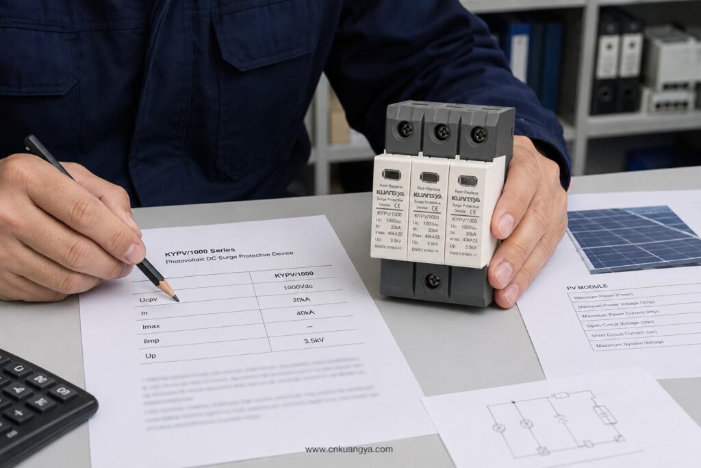
Un circuito CC fotovoltaico può essere flottante, messo a terra funzionalmente o configurato secondo una specifica topologia dell'inverter. L'SPD deve utilizzare una disposizione di collegamento adatta a tale sistema.
Prima di selezionare il numero di poli o le modalità di protezione, confermare:
Non dare per scontato che un SPD AC con una tensione simile possa essere utilizzato sul lato DC fotovoltaico. I sistemi fotovoltaici presentano caratteristiche specifiche di tensione continua e corrente di guasto. Il dispositivo deve essere progettato e testato per applicazioni fotovoltaiche in corrente continua secondo la norma IEC/UNE-EN 61643-31.
Un SPD fotovoltaico deve essere in grado di disconnettersi in sicurezza se raggiunge la fine della sua vita utile.
I parametri importanti includono:
Il fusibile di backup esterno non deve essere selezionato solo in base alle dimensioni fisiche dell'SPD. Seguire la scheda tecnica del produttore dell'SPD e verificare la compatibilità con la corrente della stringa FV e le caratteristiche di guasto del sistema.
L'SPD protegge dalle sovratensioni transitorie. Il fusibile gPV o l'interruttore DC protegge dalle condizioni di sovracorrente e cortocircuito. Un dispositivo non può sostituire l'altro.
Le posizioni tipiche per gli SPD in DC includono:
La disposizione più idonea dipende dalla lunghezza dei cavi, dall'esposizione, dal progetto di protezione contro i fulmini, dal livello di tenuta dell'apparecchiatura e dalla valutazione del rischio del progetto.
Per un'installazione compatta su tetto con percorsi brevi dei cavi in CC, un SPD di Tipo 2 vicino all'inverter può fornire la protezione richiesta quando consentito dal progetto.
Per percorsi più lunghi tra l'impianto fotovoltaico e l'inverter, potrebbero essere necessari SPD coordinati su entrambe le estremità. Ciò riduce lo stress di tensione che può svilupparsi lungo il cavo e migliora la protezione delle apparecchiature in ciascuna posizione.
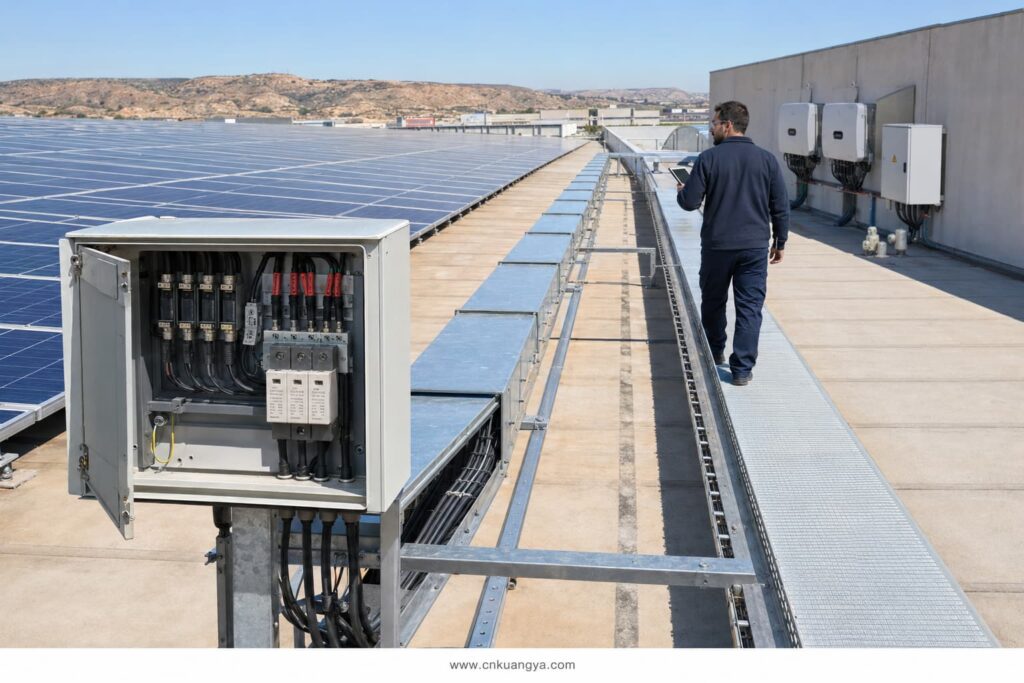
Alcune linee guida di progettazione del settore utilizzano circa 10 metri come punto in cui considerare un ulteriore coordinamento. Questa non deve essere considerata una regola universale per ogni installazione in Spagna. Il posizionamento finale deve seguire lo standard di progettazione applicabile, la valutazione del rischio, il percorso dei cavi e le istruzioni del produttore dell'apparecchiatura.
Anche un SPD correttamente dimensionato può fornire una protezione scarsa se installato con cavi lunghi o posati in modo errato.
Durante una sovratensione, l'induttanza del cavo crea una tensione aggiuntiva. Conduttori più lunghi possono quindi aumentare la tensione totale che raggiunge l'inverter.
Una buona pratica di installazione include:
L'obiettivo è ridurre la lunghezza totale del collegamento e minimizzare il livello di protezione efficace presso l'apparecchiatura protetta.
DIN-rail SPD modules do not automatically provide outdoor protection. Their environmental protection depends on the enclosure in which they are installed.
For rooftop and outdoor PV systems in Spain, check:
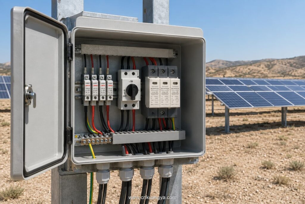
The SPD’s declared ratings apply under the operating conditions stated in its data sheet. High internal cabinet temperatures should be considered, especially in outdoor enclosures exposed to direct sunlight.
SPDs are not permanent, maintenance-free components. Their protective elements can deteriorate after repeated surge events.
Useful maintenance features include:
The module should be inspected according to the maintenance plan and after significant lightning activity or a known surge event.
Replace the module when:
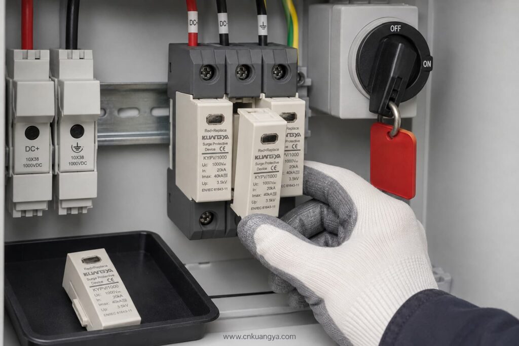
Always isolate the relevant DC circuit and follow safe working procedures before inspection or replacement.
| Project Condition | SPD Selection to Evaluate |
|---|---|
| Residential rooftop PV without expected lightning-current entry | Type 2 PV DC SPD |
| Commercial rooftop with long DC cable routes | Coordinated Type 2 SPDs at suitable locations |
| Building with an external lightning protection system | Type 1 or Type 1+2, depending on the lightning protection design |
| Utility-scale 1,500 V PV array | PV-specific 1,500 V SPD with suitable Type and discharge ratings |
| Combiner box exposed to induced surges | Type 2 PV DC SPD |
| Inverter requiring combined lightning and surge protection | Type 1+2 PV DC SPD if specified by the design |
This table is a preliminary guide only. It does not replace the project risk assessment or the work of an authorised electrical designer.
Providing complete technical information helps the supplier select the correct product and prevents delays.
Send the following details:
If the SPD type is not yet confirmed, provide the PV module data, number of modules per string, minimum design temperature, inverter model, system drawing, and lightning protection information.
Avoid these common errors:
Selecting a suitable SPD CC per impianti solari in Spagna requires coordination between the PV system voltage, lightning risk, SPD classification, installation location, earthing arrangement, and applicable Spanish requirements.
The most important steps are:
KUANGYA supplies DC SPDs for solar PV applications in 600 V, 1,000 V, and 1,500 V configurations, including Type 2 and Type 1+2 options.
View the KUANGYA DC SPD range for photovoltaic systems or contact us with your system voltage, SPD type, discharge-current requirements, wiring configuration, quantity, and project location to request a data sheet and B2B quotation.
Not automatically. Type 2 is widely used for induced lightning and switching surges, but the final selection depends on the lightning protection system, risk assessment, equipment location, and project requirements.
Only if the SPD’s Ucpv is suitable for the maximum calculated PV voltage under the lowest expected temperature. Do not rely only on the nominal system description.
In is the nominal discharge current used to evaluate repeated Type 2 surge performance. Imax is the maximum 8/20 μs discharge current the SPD can withstand under specified test conditions.
It is used where the design requires both partial lightning-current discharge and Type 2 surge-limiting performance at the same installation point.
Common locations include the combiner box and inverter DC input. Long cable routes or exposed systems may require coordinated SPDs at more than one location.
UNE-EN 61643-31 is the principal Spanish standard covering requirements and test methods for SPDs used in photovoltaic installations. The complete installation must also follow the REBT and other applicable technical requirements.
If your project has already reached the stage of deciding between Type 1, Type 2 and Type 1+2 protection, continue with our detailed guide to Type 1 vs Type 2 SPD for solar PV in Spain.
This article provides general technical guidance. Final SPD selection and installation should be verified by the responsible project designer or an authorised electrical professional in accordance with current Spanish requirements.

