منطقة ونغ يانغ الصناعية يويتشينغ ونتشو 325000
ساعات العمل
من الاثنين إلى الجمعة: 7 صباحاً - 7 مساءً
عطلة نهاية الأسبوع 10 صباحاً - 5 مساءً
منطقة ونغ يانغ الصناعية يويتشينغ ونتشو 325000
ساعات العمل
من الاثنين إلى الجمعة: 7 صباحاً - 7 مساءً
عطلة نهاية الأسبوع 10 صباحاً - 5 مساءً

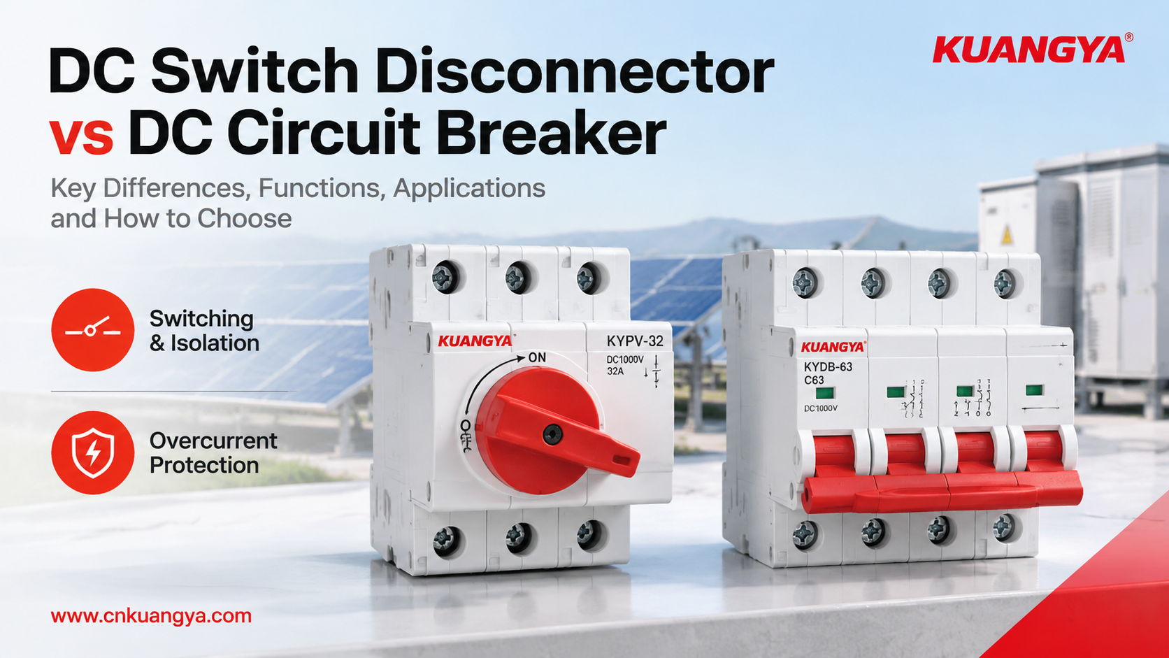
في نظام الطاقة الشمسية الكهروضوئية، فاصل قاطع التيار المستمر مقابل قاطع دائرة التيار المستمر تساعد المقارنة المهندسين والمشترين على فهم وظيفتين مختلفتين: التبديل والعزل مقابل الحماية التلقائية من التيار الزائد. على الرغم من أن هذه الأجهزة قد تبدو متشابهة، إلا أن اختيار الجهاز الخاطئ يمكن أن يترك الدائرة دون الحماية التي تحتاجها أو يجعل الصيانة أكثر صعوبة.
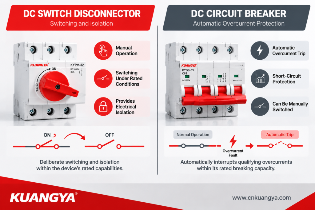
الفرق بين فاصل قاطع التيار المستمر مقابل قاطع دائرة التيار المستمر يعود إلى وظائفهما المقصودة: يوفر فاصل القاطع التبديل والعزل ضمن ظروف التشغيل المقدرة له، بينما تم تصميم قاطع الدائرة لقطع التيارات الزائدة والدوائر القصيرة المحددة تلقائيًا.
ومع ذلك، فإن التمييز ليس دائمًا بسيطًا كما يوحي اسم المنتج. تجمع بعض الأجهزة بين وظائف التبديل والعزل، وتعتمد قدراتها الفعلية على تقييماتها وتصميمها والمعايير المطبقة.
يقارن هذا الدليل بين الجهازين، ويشرح ستة اختلافات عملية، ويوضح كيفية تقييمهما في أنظمة الطاقة الشمسية الكهروضوئية (PV)، وصناديق التجميع، وتطبيقات التيار المستمر الأخرى.
النقطة الرئيسية: قاطع الدائرة المفتاح ليس جهاز حماية تلقائي من الدائرة القصيرة، ولا ينبغي افتراض أن قاطع الدائرة يوفر تلقائيًا كل وظيفة عزل مطلوبة للصيانة.
يتم تشغيل قاطع الدائرة المفتاح للتيار المستمر يدويًا بشكل عام لتوصيل أو فصل دائرة تحت ظروف محددة. يمكن لقاطع الدائرة للتيار المستمر فتح دائرة تلقائيًا عندما تكتشف آلية الحماية الخاصة به تيارًا زائدًا ضمن خصائص التشغيل الخاصة به.
| نقطة المقارنة | مفصل تبديل التيار المستمر | قاطع دارة التيار المستمر |
|---|---|---|
| الوظيفة الأساسية | التبديل والعزل الكهربائي، وفقًا لتقييمه | الحماية من التيار الزائد وفصل الدوائر |
| فصل الأحمال العادية | نعم، إذا كانت مصنفة للواجب المقصود | نعم، ضمن ظروف التشغيل المقدرة لها |
| فصل تلقائي للحمل الزائد | غير متوفرة عادةً | متوفرة في الموديلات المصممة للحماية من الحمل الزائد |
| انقطاع الدائرة القصيرة | ليست وظيفتها الأساسية المستقلة | نعم، ضمن قدرة الفصل المقدرة له |
| وظيفة العزل | يعتمد على قدرة العزل المعلنة للجهاز | يعتمد على تصميمه وعلاماته والمتطلبات المطبقة |
| التشغيل النموذجي | مقبض يدوي أو آلية دوارة | التشغيل اليدوي والتعثر التلقائي |
| أحكام القفل | قد يدعم قفلًا في وضع الإيقاف | يعتمد على الطراز والملحقات |
| عائلة معايير IEC ذات الصلة | IEC 60947-3 | IEC 60947-2 لقواطع الدائرة الصناعية |
| تطبيق نموذجي للطاقة الشمسية الكهروضوئية | الفصل المخطط له وعزل الصيانة | حماية الفروع أو المغذيات المناسبة |
يصف المقارنة وظائف المنتج النموذجية بدلاً من كل جهاز في السوق. تحقق دائمًا من ورقة بيانات وشهادة الطراز المحدد.
عند تقييم فاصل قاطع التيار المستمر مقابل قاطع دائرة التيار المستمر, ، لا تقارن المنتجات بناءً على الجهد المقنن أو التيار فقط. تحقق مما إذا كان الجهاز مصمماً لتبديل الأحمال، أو العزل الكهربائي، أو الفصل التلقائي، أو قطع دائرة القصر. يجب أن تتوافق هذه الوظائف مع المتطلبات الفعلية لدائرة التيار المستمر (DC).
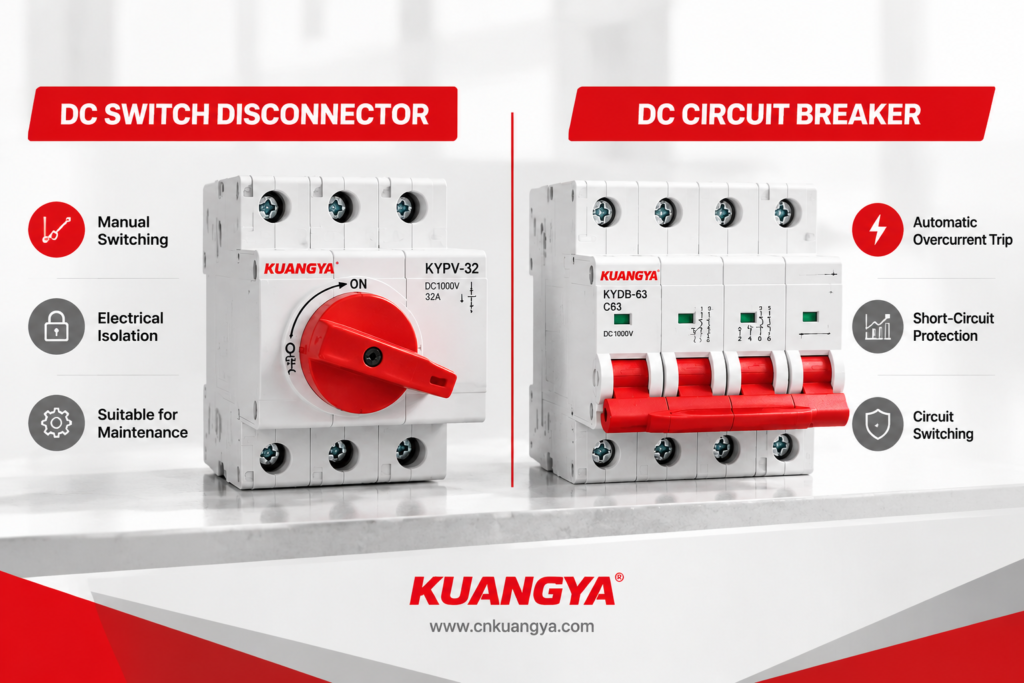
هام: لا ينبغي التعامل مع جهاز فصل أساسي مخصص للعزل فقط كمفتاح لقطع الأحمال. وبالمثل، لا ينبغي توقع أن يقوم مفتاح الفصل بقطع دائرة القصر ما لم يسمح تصنيفه المحدد أو مجموعة الحماية المعتمدة بذلك.
أهم تمييز هو ما صُمم كل جهاز للقيام به.
يوفر مفتاح الفصل للتيار المستمر وسيلة متعمدة لفتح الدائرة. للحصول على خيارات المنتجات وتفاصيل التطبيق، استكشف موقعنا مفاتيح فصل التيار المستمر للتطبيقات الشمسية الكهروضوئية وتخزين الطاقة وتطبيقات التيار المستمر الأخرى. يمكن أن يساعد في إنشاء نقطة عزل محددة قبل الفحص أو الصيانة أو استبدال المعدات، شريطة أن يكون الجهاز مناسبًا للتطبيق.
قاطع دائرة التيار المستمر يحمي دائرة مصممة بشكل مناسب ضد ظروف التيار الزائد المحددة. اعتمادًا على خصائص الفصل الخاصة به، يمكنه الاستجابة للأحمال الزائدة والدوائر القصيرة وقطع التيار ضمن قدرته المقدرة.
ضع في اعتبارك المثال التالي:
يقوم صندوق تجميع الطاقة الشمسية بتغذية دائرة تيار مستمر (DC) متصلة بعاكس (Inverter). أثناء الصيانة، يحتاج الفني إلى عزل الدائرة ذات الصلة. وفي حال حدوث تيار غير طبيعي، تحتاج الدائرة أيضاً إلى معدات حماية مناسبة لقطع التيار عند حدوث عطل.
هذه متطلبات مترابطة ولكنها مختلفة. يجب أن يحدد التصميم جهاز العزل المناسب والحماية من التيار الزائد بدلاً من توقع قيام مكون واحد بوظائف لم يتم تصنيفه لأدائها.
ليست كل المفاتيح مناسبة لفتح دائرة تيار مستمر (DC) تحت الحمل.
لا يحتوي التيار المستمر على نقاط عبور دورية للصفر كما هو الحال في التيار المتردد. عند فصل نقاط تلامس التيار المستمر، يمكن للقوس الكهربائي أن يستمر في توصيل التيار ما لم يكن الجهاز مصمماً لقطعه في ظل الظروف المحددة.
يمكن لمفتاح الفصل (Switch Disconnector) المصنف لواجب تبديل التيار المستمر ذي الصلة فتح الدائرة ضمن حدودها المعلنة. أما مفتاح الفصل المخصص للعزل بدون حمل فقد يتطلب قطع التيار بواسطة جهاز آخر مناسب أولاً.
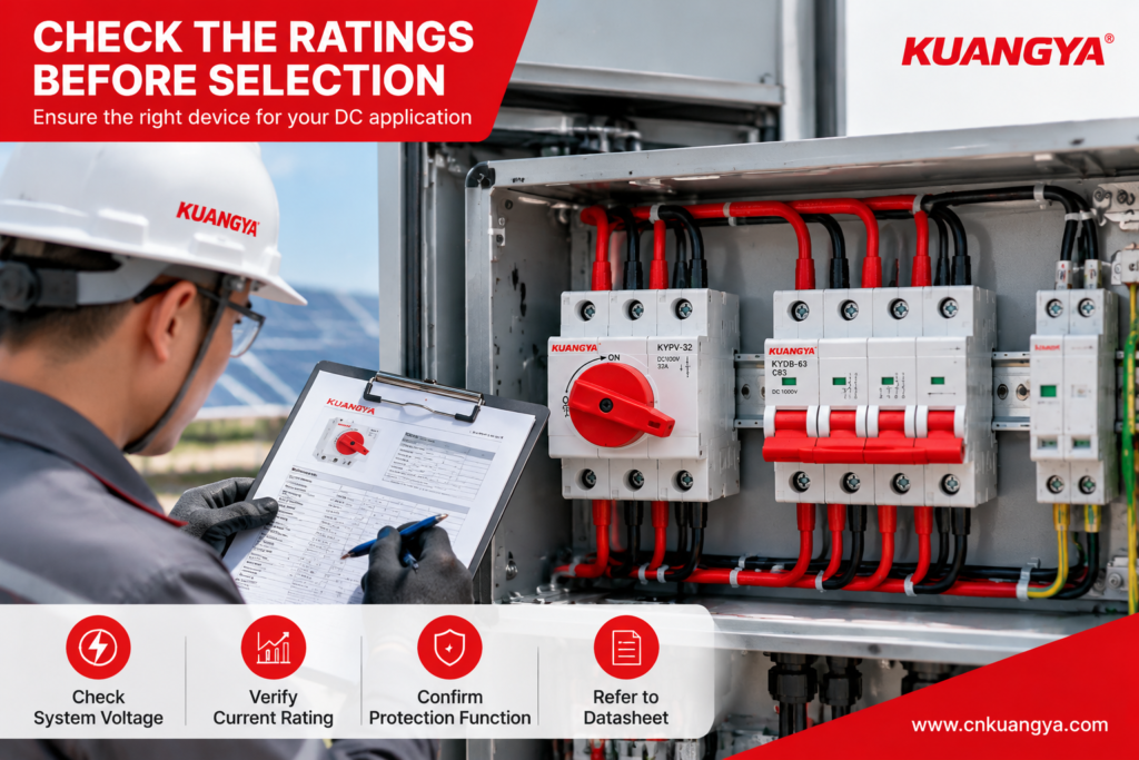
قبل اختيار الجهاز، تحقق مما يلي:
لا تفترض أن المقبض الدوار، أو الجهد العالي المطبوع على الملصق، أو علامة التشغيل/الإيقاف المرئية تثبت أن الجهاز قادر على قطع جميع أنواع أحمال التيار المستمر.
هنا يصبح التمييز مهماً بشكل خاص.
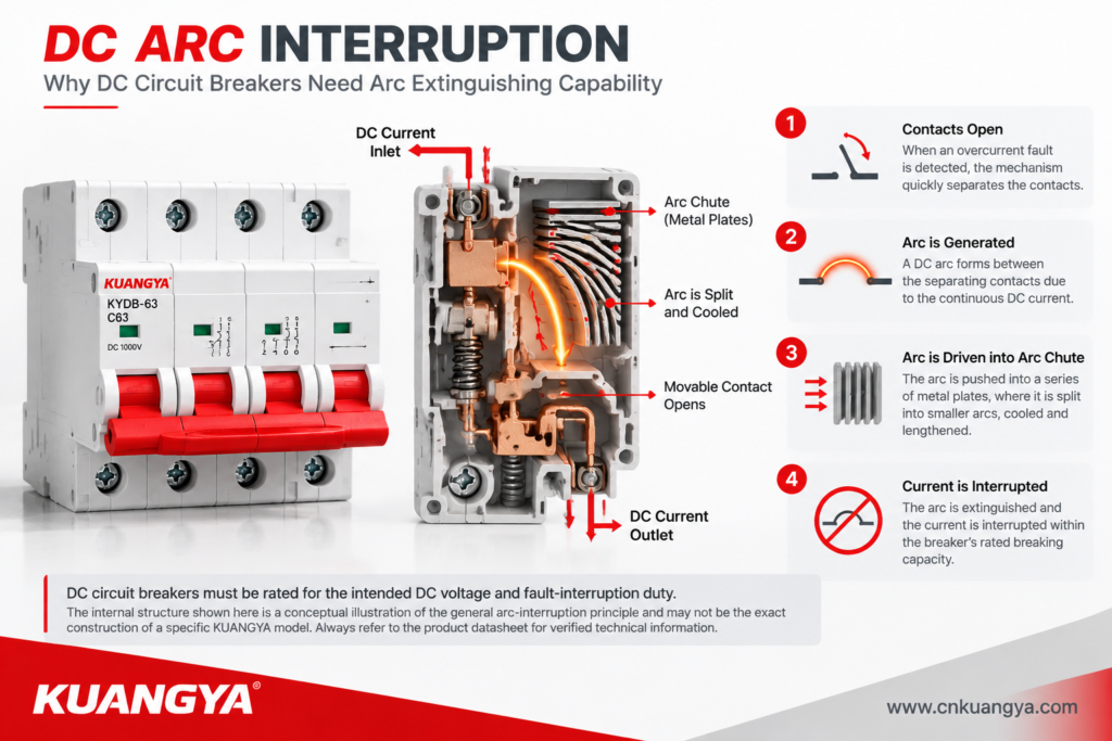
تم تصميم قاطع دائرة التيار المستمر لقطع تيارات العطل المحددة ضمن سعة القطع المقدرة وظروف التشغيل الخاصة به.
عند تقييم قاطع دائرة لتطبيق تيار مستمر، راجع سعة القطع المقدرة ومدى توافقه مع تيار العطل المحتمل للنظام. انظر إلى مجموعة قواطع التيار المستمر المصغرة (DC MCB) الخاصة بنا للحصول على خيارات المنتجات والمواصفات المقدرة.
في المقابل، لا يهدف مفتاح الفصل عادةً إلى توفير حماية تلقائية مستقلة من قصر الدائرة. قد يكون له قدرة تحمل محددة لفترة قصيرة أو تصنيف مشروط لقصر الدائرة عند استخدامه مع جهاز حماية مخصص.
هذه التصنيفات تعني أشياء مختلفة.
| التصنيف أو الميزة | ما يخبرك به | ما لا يعنيه تلقائياً |
|---|---|---|
| الجهد التشغيلي المقدر | الجهد الذي صُمم الجهاز للعمل عنده في ظل ظروف محددة | أن الجهاز يمكنه قطع أي تيار عطل عند ذلك الجهد |
| التيار المقنن | التيار المسموح به في ظل الظروف المذكورة | أن الأحمال الزائدة ستؤدي إلى فصل تلقائي |
| القدرة الاستيعابية | تيار العطل الذي يمكن لجهاز الحماية قطعه في ظل ظروف محددة | أن الجهاز مناسب لكل جهد تيار مستمر أو ترتيب دائرة |
| تيار التحمل لفترة قصيرة | تيار العطل الذي يمكن للجهاز تحمله لمدة زمنية محددة | أنه يمكنه فصل العطل بشكل مستقل |
| تصنيف تيار القصر المشروط | الأداء عند استخدامه مع ترتيب الحماية المحدد | أنه يمكن استبدال أي مصهر أو قاطع دائرة بآخر |
بالنسبة لقاطع الفصل DC، تحقق من قدرة تحمل الدائرة القصيرة المعلنة أو القدرة المشروطة والجهاز الواقي المطلوب في المنبع.
بالنسبة لقاطع الدائرة DC، تحقق من قدرة الفصل المقدرة لتيار مستمر وتأكد من أنها كافية لتيار الدائرة القصيرة المتوقع في نقطة التركيب.
يتم تشغيل قاطع الفصل التقليدي يدويًا. لا يكتشف عادةً الحمل الزائد ويتعثر تلقائيًا.
يمكن لقاطع الدائرة المزود بوظائف حماية مناسبة فتح دائرة عندما يكتشف آلية التعثر الخاصة به خطأ مؤهلًا.
يؤثر هذا الاختلاف على تشغيل النظام.
| الوضع | مفصل التبديل | قاطع دارة التيار المستمر |
|---|---|---|
| الصيانة المخطط لها | يوفر نقطة عزل يدوية مناسبة | قد يوفر التبديل والعزل إذا كان مناسبًا بشكل خاص |
| الحمل الزائد المستمر | Does not normally trip automatically | Can trip if its protection characteristics detect the overload |
| ماس كهربائي | Must not be relied upon as standalone fault protection | Can interrupt the fault within its rated capability |
| المراقبة عن بُعد | Requires suitable auxiliary contacts or additional equipment | May support auxiliary contacts or electronic monitoring, depending on model |
| Automatic fault response | غير متوفرة عادةً | Available according to the protection design |
A device’s ability to be switched remotely is not the same as its ability to provide automatic fault protection. Remote actuation, status monitoring, and protective tripping should be evaluated separately.
A 2-pole device is not automatically equivalent to a 4-pole device, and a voltage rating printed on a product should not be interpreted without checking the specified wiring arrangement.
Some DC switching devices use multiple contacts in series to achieve their declared voltage or interruption capability. In such cases, the manufacturer’s wiring diagram must be followed.
For example, a device rated for a particular DC voltage with a specified series-pole connection may not retain that rating when wired differently.
When comparing a DC switch disconnector with a DC circuit breaker, verify:
Do not choose a device based on “2P,” “4P,” or “1500V DC” alone. The complete combination of voltage, current, pole arrangement, and switching duty must match the intended application.
Maintenance safety involves more than turning a handle to OFF.
A suitable isolation arrangement should help personnel identify the correct circuit, prevent unintended reconnection, and follow the applicable safe-working procedure.
A DC switch disconnector may provide a lockable OFF position, but this feature must be confirmed for the specific model. A circuit breaker may also support locking accessories, although its suitability as the required isolation device must be verified separately.
For a planned maintenance task, consider the following:
An OFF indication alone is not proof that an electrical circuit is safe to touch.
In many photovoltaic installations, the switch disconnector and circuit breaker serve complementary roles.
A typical protection arrangement may include:
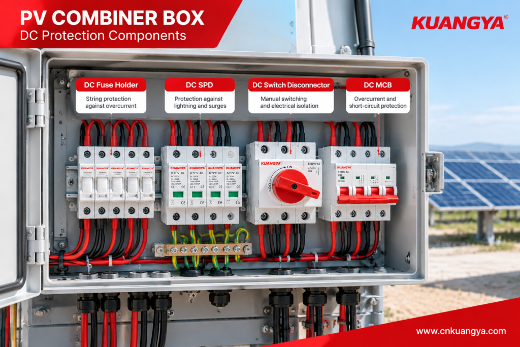
The exact arrangement depends on the system architecture, inverter requirements, prospective fault current, earthing arrangement, and applicable standards. For a closer look at how fuses, SPDs, disconnect switches, and other components work together, read our solar combiner box protection and maintenance guide. Not every installation requires all four devices in the same location.
| المكوّن | الغرض الرئيسي | Selection Check |
|---|---|---|
| gPV fuse and fuse holder | PV string overcurrent protection | Rated voltage, current, fuse characteristic, and fault-interruption capability |
| DC SPD | الحماية من الجهد الزائد العابر | PV-specific rating, protection level, and applicable SPD standard |
| مفتاح فصل التيار المستمر | التبديل والعزل | Rated DC switching duty, isolation capability, and connection arrangement |
| قاطع دارة التيار المستمر | Overcurrent protection where required | Trip characteristics, rated breaking capacity, and system compatibility |
A combiner box with a fuse, SPD, and switch disconnector does not automatically provide every protective function that a circuit breaker would provide. Each component must be selected for its intended role.
For related technical guidance, see our Solar DC Protection Guide و PV Combiner Box Guide.
The following cases are illustrative engineering scenarios based on common equipment-selection and system-coordination issues. They are not presented as documented KUANGYA customer incidents or laboratory test results.
الوضع
A panel designer selects a DC switch disconnector because its voltage and current ratings appear to match the circuit. The design does not include a suitable protective device for the relevant fault condition.
What is wrong?
The selected switch may be suitable for manual switching and isolation but may not have the capability to interrupt the prospective short-circuit current.
Corrective action
Lesson: A matching voltage and current label does not prove that a switch can clear a short circuit.
الوضع
A buyer chooses an AC-rated switching device because its current rating appears sufficient for a solar DC circuit.
What is wrong?
The device may not have been tested or rated to interrupt the specified DC current. Its arc-extinguishing design and contact arrangement may be unsuitable for the application.
Corrective action
Use a device with an explicit DC rating for the actual system voltage, current, and switching duty. Follow the manufacturer’s approved wiring diagram.
Lesson: AC and DC ratings are not interchangeable unless the manufacturer explicitly declares the relevant capability.
الوضع
A maintenance team assumes that switching a circuit breaker to OFF automatically satisfies all site isolation requirements.
What is wrong?
The breaker may not provide every required isolation, locking, or work-control feature for the particular installation. Other energy sources or backfeed paths may also remain present.
Corrective action
Check the device’s isolation suitability, locking provisions, circuit arrangement, and site procedures. Use the designated isolation method and verify the absence of voltage before work.
Lesson: Protection, isolation, and safe-work procedures are related but distinct requirements.
Use the following guide as a starting point, then confirm the choice against the applicable standard and the manufacturer’s documentation.
| Application Requirement | Appropriate Direction |
|---|---|
| Manual disconnection for planned maintenance | A suitable DC switch disconnector or isolator |
| Automatic overload protection | A suitably rated DC circuit breaker or other approved protective device |
| انقطاع الدائرة القصيرة | A protective device with sufficient DC breaking capacity |
| Both switching and isolation | A switch disconnector rated for the required duty, or another approved arrangement |
| PV string reverse-current protection | A correctly selected gPV fuse where required by the design |
| الحماية من الجهد الزائد العابر | A suitably rated DC SPD |
| Isolation and overcurrent protection | A coordinated combination of devices, unless an approved integrated solution provides the required functions |
For photovoltaic projects, the decision should be based on the system’s maximum DC voltage, current, prospective fault current, required isolation points, and applicable local requirements.
A device that is suitable for one part of a PV installation may not be suitable for another.
IEC 60947-3 covers switches, disconnectors, switch-disconnectors, and fuse-combination units within its scope. Buyers should check the applicable edition and the device’s declared ratings before selecting a product. IEC 60947-2 specifies requirements for circuit breakers within its scope, including relevant DC applications. Check the applicable edition and the manufacturer’s documentation to verify that the selected device meets the project’s requirements.
The applicable edition, product scope, and any relevant product-specific requirements should be checked for the intended application.
For more information about DC isolation principles and photovoltaic applications, see our DC switch disconnector technical guide.
Before issuing a purchase order, ask the supplier to confirm the following:
| Checkpoint | Information to Request |
|---|---|
| Product identity | Exact model and intended function |
| تصنيف الجهد | Rated DC voltage and any limitations |
| Current rating | Rated operational or continuous current under stated conditions |
| Switching duty | Permitted load-breaking conditions and utilization category |
| Fault performance | Breaking capacity for breakers; applicable withstand or conditional rating for disconnectors |
| Pole arrangement | Approved wiring diagram and pole configuration |
| العزل | Declared isolation suitability and operating indication |
| Locking | Whether the OFF position can be secured, if required |
| المعايير | Applicable standard, edition, and supporting conformity documentation |
| الملاءمة البيئية | Temperature limits, enclosure protection, terminals, and derating |
| Traceability | Model-specific datasheet, markings, and relevant test documentation |
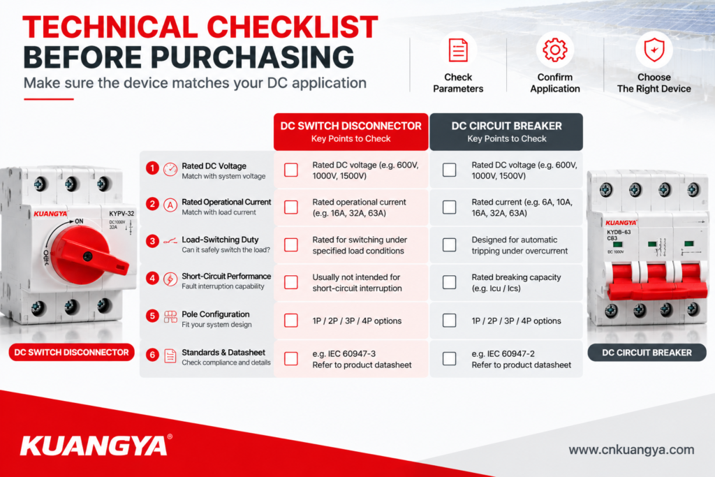
Avoid comparing suppliers solely by voltage, current, or unit price. Two products with similar front-panel markings may have different switching capabilities and short-circuit ratings.
No. A switch disconnector is intended for switching and isolation within its declared ratings. A DC circuit breaker provides automatic overcurrent protection within its rated protective capability. Their functions may overlap in some respects, but the devices are not automatically interchangeable.
Not as a general rule. A switch disconnector does not normally provide standalone automatic overload and short-circuit protection. A suitable protective device must be included where required by the system design.
Not automatically. Confirm that the breaker is suitable for the required isolation function, operating conditions, and maintenance procedures.
Each device must be rated for the actual maximum system voltage and its intended duty. A nominal 1500V system label alone is insufficient; verify the device ratings and approved connection arrangement.
IEC 60947-3 is relevant to switches, disconnectors, and switch-disconnectors. IEC 60947-2 is relevant to industrial circuit breakers. Other standards or requirements may apply depending on the product and installation.
Provide the application, maximum DC voltage, operating current, prospective fault current if known, required poles, switching duty, installation environment, quantity, and any required certifications or documentation. Include the system wiring diagram when possible.
اختيار المناسب فاصل قاطع التيار المستمر مقابل قاطع دائرة التيار المستمر solution starts with understanding the function each device needs to perform. A switch disconnector provides switching and isolation within its rated capabilities, while a circuit breaker provides automatic overcurrent protection within its rated breaking capacity. The final choice should match the system voltage, operating current, fault conditions, and applicable standards.
For solar PV systems, the right choice depends on the maximum DC voltage, operating current, prospective fault current, required isolation functions, and applicable standards. Always verify the manufacturer’s datasheet and ensure that all protective devices work together as intended.
KUANGYA provides DC switch disconnectors and DC protection components for photovoltaic and other electrical applications. If you are selecting components for a new project, contact our team with your system specifications to discuss a suitable solution.
Explore our مفصل تبديل التيار المستمر و DC MCB product ranges for more information.