Zona industriale di WengYang Yueqing Wenzhou 325000
Orario di lavoro
Da lunedì a venerdì: dalle 7.00 alle 19.00
Fine settimana: 10.00 - 17.00
Zona industriale di WengYang Yueqing Wenzhou 325000
Orario di lavoro
Da lunedì a venerdì: dalle 7.00 alle 19.00
Fine settimana: 10.00 - 17.00

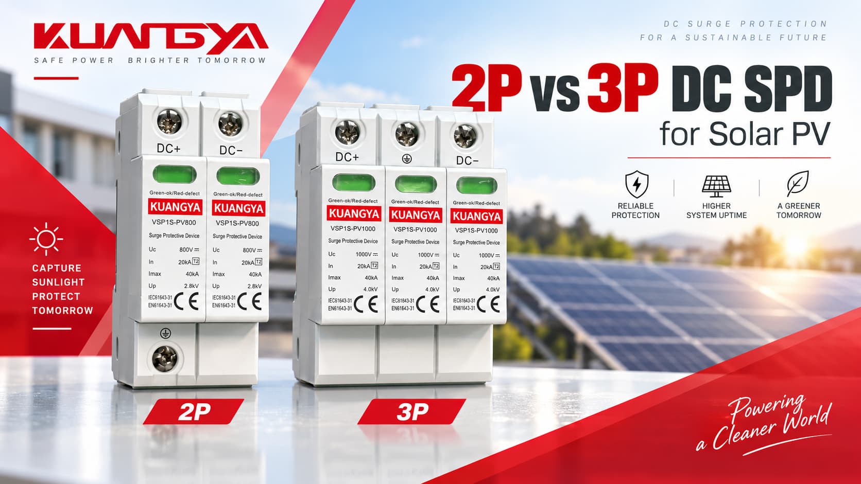
La scelta tra SPD CC 2P e 3P per il fotovoltaico solare causa spesso confusione. Una delle domande più comuni è:
Dovrei usare un SPD CC 2P o 3P?
A prima vista, la risposta sembra semplice. Una stringa FV ha conduttori CC positivi e negativi, quindi un SPD a 2 poli può sembrare sufficiente. Allora perché molti scaricatori di sovratensione fotovoltaici utilizzano tre moduli di protezione o una disposizione a tre poli?
Il motivo è che 2P e 3P non descrivono sempre lo stesso circuito di protezione interno da un produttore all'altro.
La scelta corretta dipende da:
Questa guida spiega la differenza tra SPD DC 2P e 3P, mostra esempi reali dei produttori e fornisce un metodo di selezione pratico per i sistemi solari fotovoltaici.
A Un SPD CC 2P non è automaticamente idoneo solo perché un circuito FV ha due conduttori attivi, e un Un SPD CC 3P non è automaticamente migliore solo perché dispone di un modulo aggiuntivo.
L'SPD corretto deve essere selezionato in base alla topologia elettrica e allo schema di collegamento approvato dal produttore.
| Domanda | Risposta breve |
|---|---|
| Una stringa FV ha due conduttori attivi? | Solitamente sì: CC+ e CC− |
| Ciò significa sempre che è richiesto un SPD 2P? | No |
| Il terzo modulo di un SPD 3P è semplicemente un “polo PE”? | Non necessariamente |
| Un SPD 3P è più potente di un SPD 2P? | Non intrinsecamente |
| Gli SPD 2P e 3P sono intercambiabili? | Solo se il produttore consente esplicitamente il circuito |
| Cosa conta di più? | Modalità di protezione, messa a terra del sistema, Ucpv, Iscpv e cablaggio approvato |
| Quale norma copre gli SPD CC per impianti fotovoltaici? | IEC 61643-31 |
| Quale norma disciplina la selezione e l'applicazione degli SPD per impianti fotovoltaici? | IEC 61643-32 |
La regola più sicura è:
Non selezionare un SPD fotovoltaico basandoti solo sul conteggio dei moduli. Leggi lo schema elettrico del produttore e conferma che l'SPD sia approvato per la topologia del tuo impianto fotovoltaico.
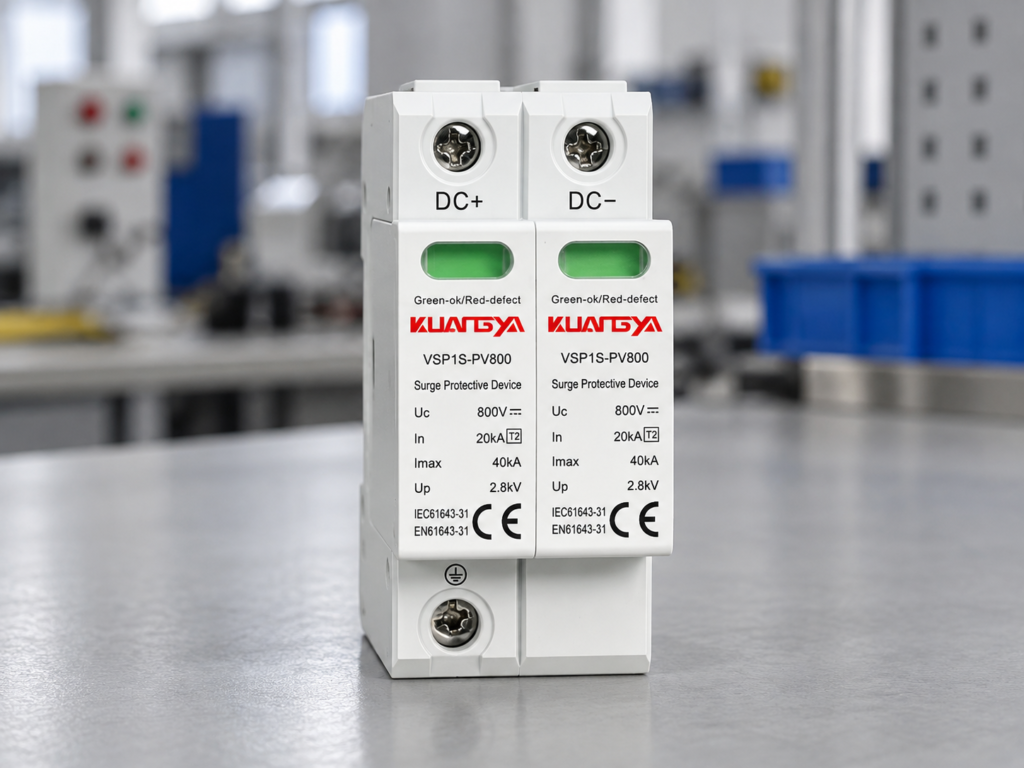
Nella terminologia elettrica quotidiana, “P” significa solitamente polo.
Tuttavia, la terminologia degli SPD fotovoltaici è meno immediata di quella degli interruttori automatici.
A seconda del produttore, la descrizione del prodotto può riferirsi a:
Questi termini sono correlati, ma sono non sempre intercambiabili.
Ad esempio, un produttore potrebbe descrivere un dispositivo come un SPD fotovoltaico a 2 poli, mentre un altro prodotto che protegge gli stessi conduttori DC+ e DC− può contenere fisicamente tre elementi di protezione sostituibili.
Questo è uno dei motivi principali per cui gli acquirenti non dovrebbero confrontare gli SPD fotovoltaici solo in base all'aspetto.
Questi tre concetti dovrebbero essere distinti.
| Termine | Cosa descrive | Perché è importante |
|---|---|---|
| Conduttore protetto | Il conduttore elettrico che viene protetto | Solitamente DC+ e DC− in una stringa FV |
| Polo/modulo | Elemento SPD fisico o elettrico | Terminologia specifica del produttore |
| Modo di protezione | Percorso attraverso il quale viene limitata la sovratensione | Determina quali condizioni di sovratensione l'SPD può gestire |
| Collegamento PE | Collegamento alla terra di protezione | Fornisce un riferimento/percorso di scarica per le sovratensioni |
| Circuito a Y | Circuito di protezione interno disposto in configurazione a Y | Comune negli SPD per impianti fotovoltaici |
| Posizione della base | Posizione fisica del modulo su guida DIN | Non sempre corrisponde al numero di conduttori protetti |
Ciò significa che:
Due conduttori CC protetti non richiedono necessariamente solo due cartucce SPD fisiche.
Lo stesso principio si applica anche al lato AC: il numero di moduli da solo non definisce il circuito interno, come spiegato nel nostro Confronto tra SPD 3+1 e 4+0.
Gli impianti fotovoltaici creano diverse condizioni particolari che non esistono in un normale quadro di distribuzione AC da 230/400 V.
Un SPD per fotovoltaico deve operare in presenza di:
A differenza della corrente alternata, la corrente continua non attraversa naturalmente lo zero a ogni semiperiodo.
Per questo motivo, l'interruzione del guasto e la progettazione interna degli SPD sono particolarmente importanti sul lato in corrente continua.
IEC 61643-31 copre specificamente gli SPD destinati al lato in corrente continua di impianti fotovoltaici fino a 1500 V CC.
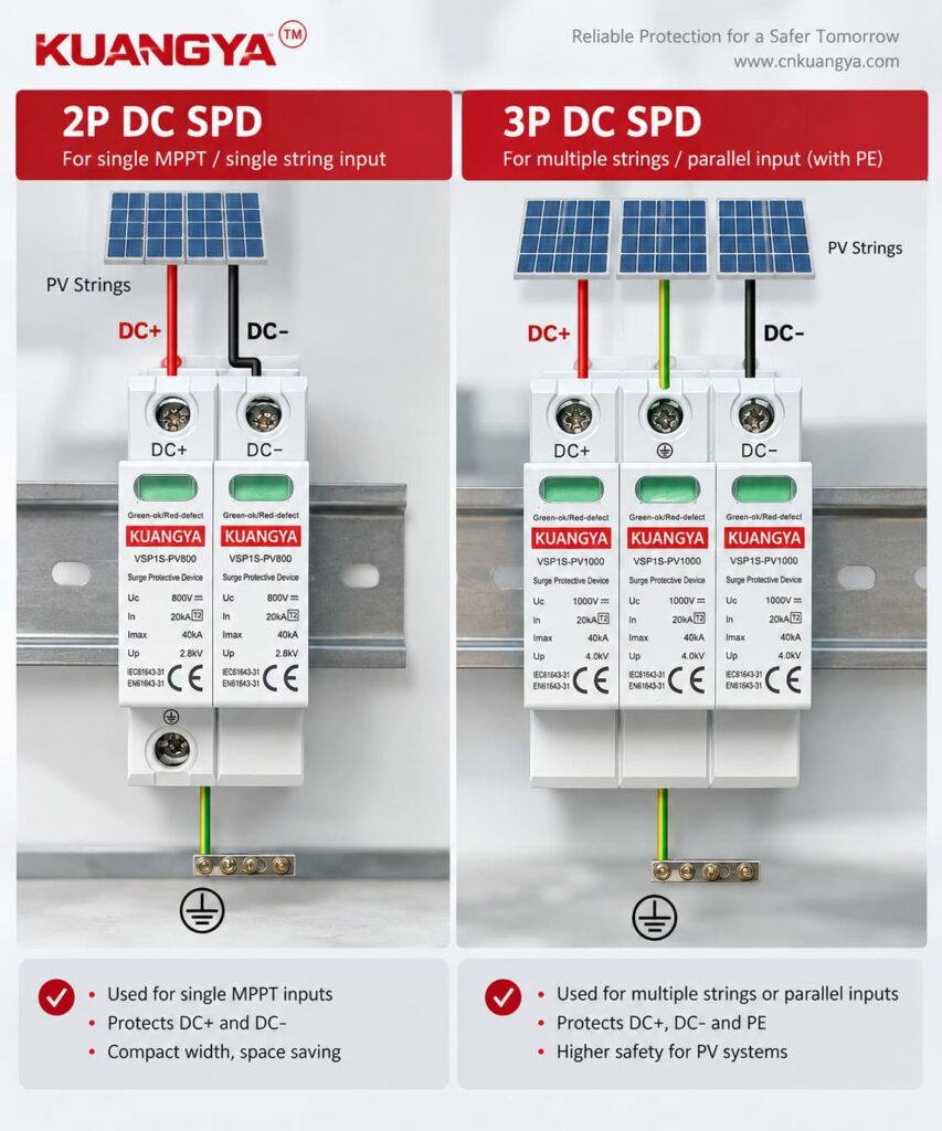
Un SPD fotovoltaico potrebbe dover limitare la tensione tra diversi punti.
Le modalità di protezione tipiche includono:
| Modalità di protezione | Descrizione |
|---|---|
| DC+ → PE | Sovratensione tra il conduttore positivo e la terra |
| DC− → PE | Sovratensione tra il conduttore negativo e la terra |
| DC+ → DC− | Sovratensione differenziale tra i due conduttori DC |
A correctly designed PV SPD can provide several of these protection paths through its internal network.
This is why looking only at the number of visible modules can be misleading.
For example, Phoenix Contact publishes PV SPDs using a Y configuration that provide protection modes between:
even though the manufacturer’s naming may refer to a “2+V” arrangement. Phoenix Contact lists these modes explicitly for its 1000 V PV devices.
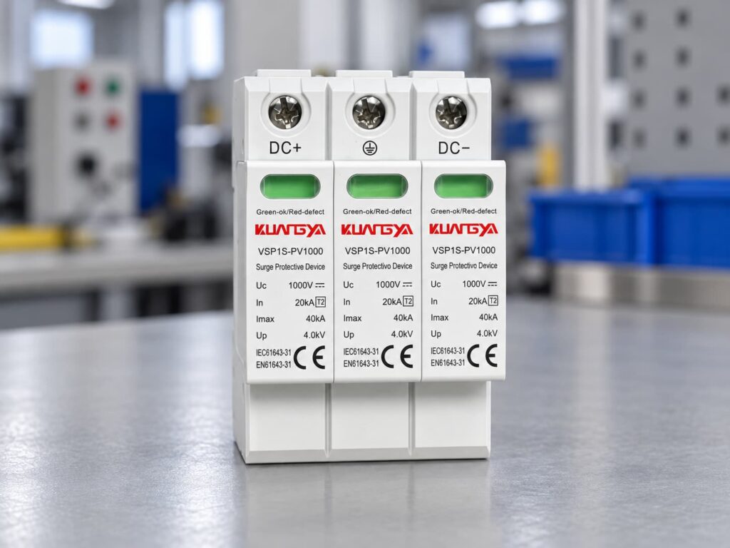
A Y-circuit is a common protective arrangement used in photovoltaic surge protection.
Instead of simply placing one MOV from positive to earth and another MOV from negative to earth, the SPD uses a coordinated internal network.
Conceptually:
DC+
↓
Elemento di protezione
↓
Common protection point
↓
Elemento di protezione
↓
PE
and another path connects the DC− conductor into the protective network.
The exact circuit varies by manufacturer.
The important point is that the internal network can provide protection for both:
while also addressing PV-specific fault conditions.
OBO, for example, describes its 1000 V PV surge protection solution as using an error-resistant Y circuit.
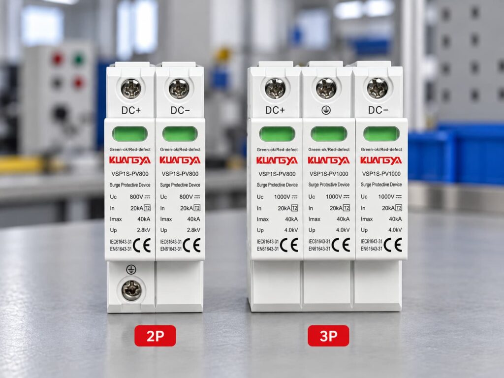
The following table provides a useful engineering comparison, but the manufacturer’s wiring diagram always takes priority.
| Caratteristica | 2P DC SPD | 3P / Three-Module DC SPD |
|---|---|---|
| Physical size | Often smaller | Usually wider |
| Number of visible modules | Often 2 | Often 3 |
| DC conductors protected | Typically DC+ and DC− | Typically DC+ and DC− |
| Collegamento PE | May be included | Usually included |
| Internal circuit | Depends on manufacturer | Often PV-specific Y circuit |
| Suitable for floating PV | Model-dependent | Common, but still model-dependent |
| Suitable for grounded PV | Model-dependent | Model-dependent |
| Differential protection | Check datasheet | Check datasheet |
| Common-mode protection | Check datasheet | Common on PV-specific designs |
| Costo | Often lower | Often slightly higher |
| DIN rail width | Di solito più piccoli | Usually larger |
| Better protection? | Non automaticamente | Non automaticamente |
The key difference is therefore not simply “two modules versus three modules.”
The real difference is the approved protection circuit behind those modules.
OBO publishes a V20 1000 V DC photovoltaic surge protective device described as:
V20-C 2-PH-1000
The manufacturer identifies it as:
2-pole for earthed PV systems.
Published specifications include approximately:
| Specifiche | OBO V20-C 2-PH-1000 |
|---|---|
| Applicazione | Earthed PV systems |
| Pole version | 2 |
| Maximum continuous DC voltage | 1000 V CC |
| Tipo | Tipo 2 |
| Nominal discharge current In | 20 kA |
| Maximum discharge current Imax | 40 kA |
| Voltage protection level Up | ≤4.0 kV |
| Installazione | Guida DIN da 35 mm |
This is a good example of why the phrase “2P DC SPD” requires context.
OBO specifically associates this configuration with earthed photovoltaic systems rather than presenting it as a universal solution for every PV system.
OBO also offers:
This product is described as:
3-pole for PV systems.
Its published data includes:
| Specifiche | OBO V20-C 3-PH-1000 |
|---|---|
| Pole version | 3 |
| Maximum continuous voltage | 1000 V CC |
| Tipo | Tipo 2 |
| Nominal discharge current In | 20 kA |
| Maximum discharge current Imax | 40 kA |
| Voltage protection level Up | ≤4.0 kV |
| Circuit | PV Y circuit |
| Installazione | Guida DIN da 35 mm |
OBO also describes this product family as using an error-resistant Y circuit for PV applications.
Notice something important:
The 2-pole and 3-pole products can have very similar headline ratings:
Yet their intended system configurations are different.
This demonstrates why voltage and kA values alone are not enough to select an SPD.
Phoenix Contact’s VAL-MS 1000DC-PV/2+V-FM provides another useful example.
Its VALVETRAB PV devices use a Y configuration and provide protection modes including:
One published Type 2 model for a 1000 V DC PV system has:
| Parametro | Published Value |
|---|---|
| Ucpv | 1000 V CC |
| Iscpv | 2000 A |
| In | 20 kA |
| Imax | 40 kA |
| Su | ≤3.3 kV |
| Circuit | Y configuration |
| Protection modes | L+/L−, L+/PE, L−/PE |
Phoenix Contact describes this product as being suitable for a two-position isolated 1000 V DC system, yet the internal circuit still provides three protection relationships.
Again, this proves that:
Number of active PV conductors ≠ number of internal surge protection elements.
ABB provides perhaps the clearest example of why terminology can confuse buyers.
ABB’s OVR PV Type 2 series specifies:
Protected lines: 2
but the protection modes include:
ABB lists PV models for both:
For its 1000 V Type 2 product, published characteristics include:
| Parametro | ABB OVR PV T2 40-1000 |
|---|---|
| Protected lines | 2 |
| Ucpv | 1000 V CC |
| Imax | 40 kA |
| In | 20 kA |
| Su | 4 kV |
| Iscpv | 10 kA |
| Protection modes | DC+/DC−, DC+/G, DC−/G |
For its 1500 V version:
| Parametro | ABB OVR PV T2 40-1500 |
|---|---|
| Protected lines | 2 |
| Ucpv | 1500 V CC |
| Imax | 40 kA |
| In | 15 kA |
| Su | 5 kV |
| Iscpv | 10 kA |
ABB’s data demonstrates an important distinction:
“Protected lines: 2” does not mean the SPD only provides two possible surge paths.
DEHN also publishes a 1000 V photovoltaic Type 2 SPD described as a:
two-pole surge arrester
for protecting one MPP input.
One DEHNcube YPV SCI 1000 model has published characteristics including:
| Parametro | Published Value |
|---|---|
| Applicazione | One MPP input |
| SPD type | Tipo 2 |
| Ucpv | 1000 V |
| Iscpv | 1 kA |
| In | 12,5 kA |
| Imax | 25 kA |
| Su | ≤4 kV |
| Grado di protezione | IP65 |
DEHN also emphasizes a PV-specific Y circuit and its DC disconnection technology.
The lesson is again the same:
“2-pole” alone does not tell you whether the device matches your PV architecture.
| Manufacturer Example | Manufacturer Terminology | PV Voltage | Key Point |
|---|---|---|---|
| OBO V20-C 2-PH-1000 | A 2 poli | 1000 V | Specified for earthed PV systems |
| OBO V20-C 3-PH-1000 | A 3 poli | 1000 V | PV Y-circuit design |
| Phoenix Contact VALVETRAB | 2+V / Y configuration | 1000 V | Protects L+/L− and both lines to PE |
| ABB OVR PV | 2 protected lines | 1000/1500 V | Multiple protection modes despite two protected conductors |
| DEHNcube YPV SCI | A 2 poli | 1000 V | PV-specific design for one MPP input |
This is why professional SPD selection should be based on the manufacturer’s protection circuit, not only a marketplace listing that says “2P” or “3P.”
This is one of the most common questions.
La risposta breve è:
Non necessariamente.
PE means protective earth.
In a PV SPD, PE may be connected to one or more internal surge protection components, but the PE terminal is not always counted as an additional “pole” in the product name.
Manufacturer terminology varies.
Ad esempio:
Pertanto:
Never assume that a “3P SPD” means “DC+, DC− and PE are three equivalent poles.”
They are not equivalent conductors.
Not automatically.
A three-module product can be highly suitable for one PV topology and incorrect for another.
Likewise, a two-pole product specifically designed for a particular grounded system may be exactly what the manufacturer requires.
A better comparison is:
| Bad Selection Question | Better Selection Question |
|---|---|
| Which has more poles? | Which topology is approved for my PV system? |
| Which has more modules? | Which protection modes are provided? |
| Which has the larger kA number? | Are In, Imax/Iimp and Up suitable for the application? |
| Which one is cheaper? | Does it comply with the required PV SPD standard? |
| Is 3P stronger? | Is the device designed for my earthing arrangement? |
The internal circuit matters more than the number printed after “P.”
Before choosing between different SPD arrangements, determine how the PV DC side is referenced to earth.
Two broad situations may occur.
Neither DC+ nor DC− is intentionally bonded directly to PE under normal operating conditions.
This arrangement is common in many modern PV inverter systems.
The SPD must be suitable for the insulation and monitoring concept of the inverter and PV generator.
One part of the DC system is intentionally referenced to earth according to the system design.
A manufacturer may provide a specific SPD arrangement for this configuration.
For example, OBO explicitly markets its 2-pole 1000 V model for earthed PV systems.
This is why installers should never convert between configurations simply to reduce the number of SPD modules.
Another common misunderstanding is mixing up:
pole configuration
with:
Type 1, Type 1+2 or Type 2.
They describe different characteristics.
| Termine | Significato |
|---|---|
| 2P / 3P | Pole or module arrangement |
| Tipo 1 | Lightning-current-capable SPD test category |
| Tipo 2 | Surge protection tested with 8/20 µs current waveform |
| Tipo 1+2 | Combined lightning-current and surge protection functionality |
| Ucpv | Maximum continuous PV operating voltage |
| In | Corrente nominale di scarica |
| Imax | Corrente massima di scarica |
| Iimp | Impulse discharge current |
| Su | Livello di protezione contro le sovratensioni |
| Iscpv | PV short-circuit current rating |
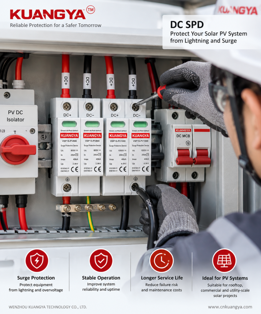
A 3P Type 2 SPD e una 3P Type 1+2 SPD are therefore not the same device.
Likewise, a 2P Type 2 cannot be replaced with a 3P Type 1+2 simply because the second product appears “bigger.”
No.
The PV voltage does affect SPD selection, but it does not by itself determine pole arrangement.
For example, PV SPDs are available for:
The key voltage parameter is normally Ucpv, the maximum continuous operating voltage of the PV SPD.
For a detailed method of selecting 600V, 1000V, or 1500V protection, see our DC SPD voltage selection guide for solar PV systems.
Ucpv must be suitable for the maximum voltage that can appear in the PV array.
PV module open-circuit voltage rises when cell temperature falls.
Therefore, the system’s maximum possible string voltage may be higher than the simple STC Voc calculation.
A simplified selection process is:
Maximum string voltage ≈ number of modules in series × module Voc × low-temperature correction factor
The exact correction should follow:
The selected SPD must have a Ucpv rating appropriate for the resulting maximum PV voltage.
Consider a commercial PV installation with:
Approximate maximum string voltage:
18 × 49 × 1.12 = 987.8 V
A 600 V SPD would clearly be unsuitable.
The designer would need a PV SPD whose Ucpv safely accommodates the calculated voltage according to the manufacturer’s selection rules.
But after establishing the voltage requirement, the designer must still determine:
Only then should pole configuration be selected.
Imagine two products listed online:
At first glance, Product B may appear “better.”
But that conclusion is impossible without knowing:
| Required Information | Product A | Product B |
|---|---|---|
| Ucpv | ? | ? |
| In | ? | ? |
| Imax | 40 kA | 40 kA |
| Iimp | ? | ? |
| Su | ? | ? |
| Iscpv | ? | ? |
| Circuit topology | ? | ? |
| Grounded/floating system approval | ? | ? |
| IEC 61643-31 | ? | ? |
| Internal disconnection | ? | ? |
If these values are missing, the pole count provides very little useful information.
For PV SPD procurement, we recommend checking parameters in approximately this order:
| Priority | Parametro | Perché è importante |
|---|---|---|
| 1 | Applicazione | Must be designed for PV DC |
| 2 | Ucpv | Must withstand continuous PV voltage |
| 3 | System topology | Grounded/floating arrangement |
| 4 | Protection modes | Confirms actual surge paths |
| 5 | Tipo | Type 1, Type 1+2 or Type 2 |
| 6 | Su | Determines clamping/protection level |
| 7 | In | Normal surge discharge capability |
| 8 | Imax / Iimp | Surge or lightning-current capability |
| 9 | Iscpv | PV short-circuit withstand/failure capability |
| 10 | Disconnection system | Important for safe end-of-life behavior |
| 11 | Backup protection | Must match manufacturer requirements |
| 12 | Pole/module arrangement | Select only after topology is confirmed |
If you are not familiar with these ratings, our guide to DC SPD specifications such as Ucpv, In, Imax, Up and Iscpv explains what each value means and how they differ.
This order avoids one of the most common purchasing mistakes: choosing an SPD by voltage, kA and pole count while ignoring the internal circuit.
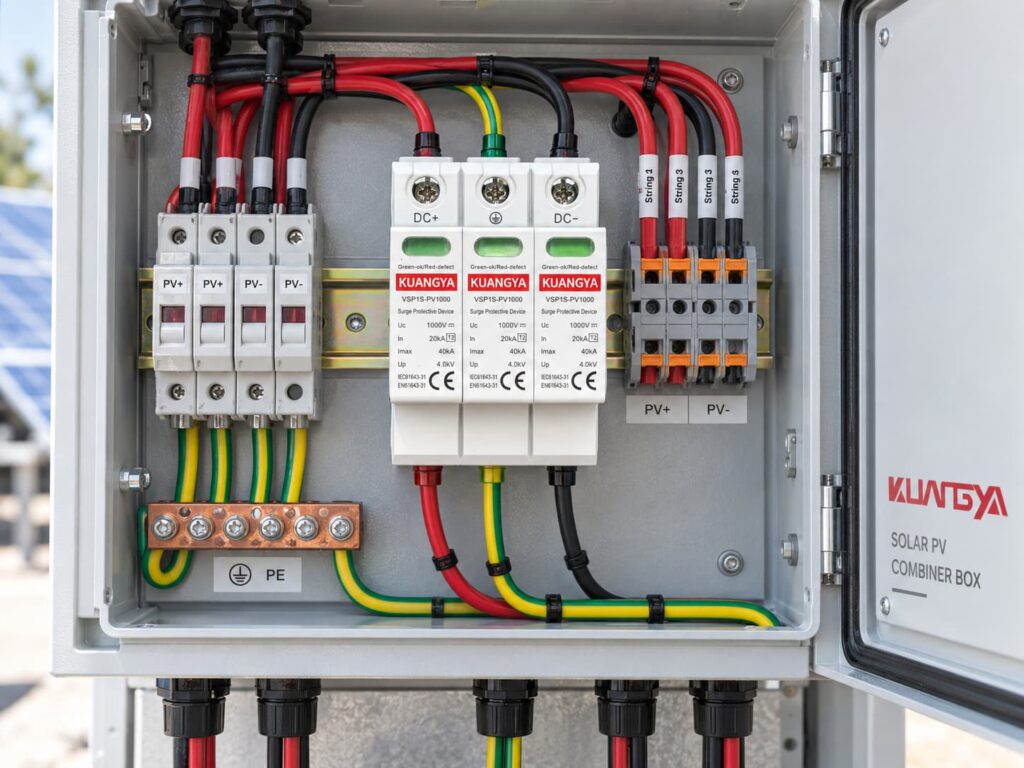
The PV combiner box is one of the most common locations for a DC SPD.
A typical combiner box may include:
The correct SPD configuration depends on the electrical design rather than simply the number of incoming strings.
Ad esempio:
Six PV strings entering one combiner box does not mean you need six SPDs.
Similarly:
Two output conductors do not automatically mean the SPD must be 2P.
The SPD protects the electrical node according to its approved circuit arrangement.
Sometimes yes.
If an inverter contains multiple independent MPPT inputs, the surge protection arrangement should be evaluated for each input group.
Factors include:
OBO, for example, publishes PV generator connection boxes designed for one, two and three MPPT configurations, showing that MPPT architecture can directly affect surge-protection layout.
Do not assume so.
Replacement is appropriate only when all of the following are verified:
If the original product uses a Y circuit and the replacement uses a different internal topology, matching the voltage and kA ratings alone is not enough.
The same rule applies.
More modules do not automatically make a product compatible.
A different internal circuit may:
Therefore, substitutions should be based on the electrical specification, not physical appearance.
“The PV string has DC+ and DC−, therefore I need a 2P SPD.”
This is too simplistic.
Check the manufacturer’s approved circuit.
PE is not simply another current-carrying pole.
The manufacturer’s internal SPD architecture determines how it is used.
A three-module device is not automatically safer or stronger.
Two 1000 V SPDs may have completely different:
A large Imax number makes an attractive product label, but it is only one parameter.
Always evaluate In, Up, Iscpv, Ucpv and circuit topology together.
For photovoltaic generator DC-side SPDs, IEC 61643-31 is the key product standard.
IEC 61643-32 addresses selection and application principles for SPDs connected to the DC side of PV systems.
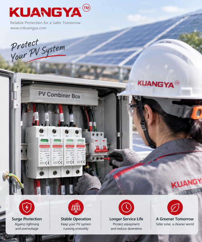
A practical 2P vs 3P DC SPD selection should start with the PV system topology rather than the number of modules.
Do not substitute an AC SPD simply because its voltage looks similar. If you are comparing AC and DC protection devices, read Can an AC SPD Be Used on a DC System? before making a substitution.
Determine maximum cold-weather string Voc.
Then select an SPD with a suitable Ucpv rating.
Determine whether:
Check the inverter manual.
Typical requirements may include:
Verify these in the SPD datasheet.
This depends on the lightning protection concept and installation architecture.
Do not use pole count as a substitute for SPD type.
Never evaluate these values individually.
This is the point where the real answer to 2P vs 3P normally becomes clear.
Check whether the SPD requires:
Follow the SPD manufacturer’s data.
For a more detailed explanation, see our guide to SPD backup fuse and circuit breaker selection.
Keep SPD connecting conductors short.
The distance between the PV array, SPD, and inverter can also affect the overall protection concept. See our detailed guide to SPD distance from the inverter in solar PV systems.
For commercial projects, request:
Before ordering a 2P or 3P PV SPD, send the supplier this information:
| Informazioni da fornire | Esempio |
|---|---|
| Applicazione | Solare fotovoltaico |
| Maximum DC voltage | 1000 V CC |
| Maximum string Voc | 920 V |
| Sistema di messa a terra | Floating / isolated |
| SPD type | Tipo 2 |
| Required In | 20 kA |
| Required Imax | 40 kA |
| Installazione | Scatola combinatore FV |
| Contatto remoto | Required / not required |
| Quantità | 500 pcs |
| Target standard | IEC 61643-31 |
A professional supplier should then confirm the suitable circuit rather than simply responding with “2P” or “3P.”
Use this table only as a preliminary guide.
| Situazione | Cosa fare |
|---|---|
| Supplier only says “2P 1000 V 40 kA” | Ask for wiring diagram and IEC data |
| Supplier only says “3P is better” | Ask for the protection circuit |
| PV DC side is floating | Use an SPD specifically approved for the floating/isolated topology |
| PV DC side is intentionally grounded | Use the manufacturer’s approved grounded-system configuration |
| System is 1500 V | Verify Ucpv and all 1500 V-specific ratings |
| Inverter already contains SPD | Check whether external SPD is still required based on cable length and protection architecture |
| Ingressi MPPT multipli | Evaluate each MPPT circuit separately |
| Existing 3-module SPD needs replacement | Match electrical topology, not just physical size |
| PE connection is unclear | Do not install until the manufacturer’s diagram is confirmed |
The following 2P vs 3P DC SPD FAQs address several common questions from PV installers, system designers, and buyers.
It can be, provided the SPD is specifically designed and approved for that PV topology.
The number “2P” alone is not enough information to make the decision.
Because the SPD may use multiple internal protective elements to provide coordinated protection between DC+, DC− and PE.
The physical module count does not necessarily equal the number of active conductors.
Not universally.
Manufacturers use different terminology.
Always check the internal wiring diagram.
Not automatically.
Safety depends on correct circuit design, voltage rating, fault-current capability, disconnection system and correct installation.
Do not do this unless the manufacturer’s instructions explicitly show that connection method.
Unused or incorrectly connected protection elements can change the intended surge protection circuit.
No, unless the manufacturer explicitly rates the product for the actual maximum continuous PV voltage.
A 1000 V Ucpv device is not suitable for a PV system that can exceed its approved continuous voltage.
Non necessariamente.
First determine whether the numbers refer to:
Then compare Up, Ucpv, Iscpv and the complete protection circuit.
Non necessariamente.
Some inverters contain integrated SPDs.
Whether additional external protection is required depends on:
If your inverter already includes surge protection, see Does a Solar Inverter With a Built-In SPD Still Need an External SPD? for a detailed explanation of when additional protection may still be required.
IEC 61643-31 covers SPDs intended for the DC side of photovoltaic installations up to 1500 V DC.
IEC 61643-32 provides selection and application principles for PV surge protective devices.
The most important point in a 2P vs 3P DC SPD comparison is that the difference is not simply the number of modules.
A photovoltaic SPD must be selected as part of an electrical protection system.
Before choosing a 2P or 3P configuration, confirm:
Real products from OBO, Phoenix Contact, ABB and DEHN show that manufacturers use different terms such as 2-pole, 3-pole, 2+V, two protected lines and Y configuration for PV surge protection.
That is why professional selection should start with the circuit diagram and datasheet—not the number of visible cartridges.
For solar PV projects, the correct question is therefore not:
“Is 2P or 3P better?”
È:
“Which SPD circuit is designed for my PV system topology?”
Always follow the latest product datasheet, inverter manufacturer instructions and applicable local electrical regulations when designing or installing surge protection.

