منطقة ونغ يانغ الصناعية يويتشينغ ونتشو 325000
ساعات العمل
من الاثنين إلى الجمعة: 7 صباحاً - 7 مساءً
عطلة نهاية الأسبوع 10 صباحاً - 5 مساءً
منطقة ونغ يانغ الصناعية يويتشينغ ونتشو 325000
ساعات العمل
من الاثنين إلى الجمعة: 7 صباحاً - 7 مساءً
عطلة نهاية الأسبوع 10 صباحاً - 5 مساءً

آخر تحديث: 14 يوليو 2026 | الإصدار 1.0
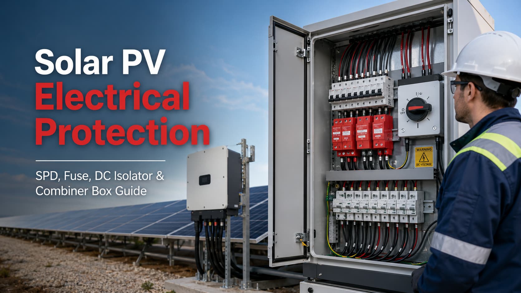
لا يعتمد نظام الطاقة الشمسية الموثوق به على جهاز حماية واحد. الحماية الفعالة الحماية الكهربائية للطاقة الشمسية الكهروضوئية تتطلب حماية منسقة عبر مسار التيار المستمر بالكامل - بدءاً من الوحدات والسلاسل الكهروضوئية وصولاً إلى صندوق التجميع، والعاكس، ونظام توزيع التيار المتردد.
منطق الحماية الأساسي هو:
وحدة كهروضوئية ← سلسلة كهروضوئية ← مصهر (فيوز) gPV ← صندوق تجميع ← جهاز حماية من زيادة التيار (SPD) للتيار المستمر ← عازل تيار مستمر ← عاكس ← حماية التيار المتردد
يعالج كل مكون خطراً كهربائياً مختلفاً:
أهم مبدأ هندسي هو ببساطة:
لا يمكن للمنصهر (Fuse) أن يحل محل جهاز الحماية من زيادة التيار (SPD)، ولا يمكن لجهاز الحماية من زيادة التيار أن يحل محل المنصهر. كما أن عازل التيار المستمر (DC isolator) ليس جهاز حماية من التيار الزائد، وتعتمد سلامة صندوق التجميع (Combiner box) على المكونات الموجودة بداخله ومدى التنسيق بينها.
يتم تناول تصميم مصفوفات الطاقة الشمسية الكهروضوئية الحديثة من خلال IEC 62548-1:2023+AMD1:2025, ، والذي يغطي توصيلات مصفوفة الطاقة الشمسية، والحماية الكهربائية، وأحكام التبديل والتأريض. الإصدار الموحد الحالي هو IEC 62548-1:2023 مع التعديل 1:2025. IEC 60364-7-712:2025 يتناول متطلبات التركيبات الكهربائية المرتبطة بأنظمة إمداد الطاقة الكهروضوئية.
يشرح هذا الدليل كيفية عمل وظائف الحماية هذه معاً، وكيف يمكن للمهندسين ومقاولي الهندسة والمشتريات والبناء (EPC) ومكاملي الأنظمة ومصممي الكهرباء بناء بنية حماية أكثر تنسيقاً لأنظمة الطاقة الشمسية الكهروضوئية.
الحماية الكهربائية للطاقة الشمسية الكهروضوئية هي التطبيق المنسق لأجهزة الحماية الكهربائية وتدابير التصميم المستخدمة لتقليل المخاطر الناجمة عن التيار الزائد، والدوائر القصيرة، والتيار العكسي، والجهد الزائد العابر، وفشل العزل، وعمليات التبديل، والقوس الكهربائي، وأعطال المعدات في الأنظمة الكهروضوئية.
لا يعد تركيب النظام الكهروضوئي مجرد مجموعة من الألواح الشمسية المتصلة بعاكس.
إنه نظام توليد كهربائي ذو خصائص تشغيل فريدة.
على عكس دائرة حمل التيار المتردد التقليدية، تنتج المصفوفة الكهروضوئية الكهرباء كلما توفر ضوء الشمس الكافي. وبالتالي، قد يظل جانب التيار المستمر نشطاً حتى عند فصل مصدر التيار المتردد.
لهذا الاختلاف عواقب وخيمة على تصميم الحماية.
يجب أن تأخذ استراتيجية الحماية الكاملة في الاعتبار ما يلي:
لا يمكن لأي مكون حماية فردي التعامل مع كل هذه المخاطر.
يستخدم النظام المصمم جيداً عدة طبقات من الحماية، حيث يؤدي كل جهاز وظيفة محددة.
هذا هو أساس التنسيق. الحماية الكهربائية للطاقة الشمسية الكهروضوئية.
تخلق الأنظمة الكهروضوئية ظروفاً كهربائية تختلف جوهرياً عن دوائر المباني العادية.
فتح قاطع التيار المتردد (AC) الرئيسي لا يؤدي بالضرورة إلى إزالة الجهد عن مصفوفة الألواح الكهروضوئية.
عندما يصل ضوء الشمس إلى الألواح، يمكن للسلاسل الاستمرار في توليد جهد التيار المستمر.
وبالتالي، قد يواجه موظفو الصيانة موصلات حية بين:
ولهذا السبب، تعد إجراءات العزل ووضع العلامات واختيار المعدات والصيانة المناسبة أمراً ضرورياً.
يمر التيار المتردد طبيعياً عبر الصفر مرتين خلال كل دورة كهربائية. يمكن أن يساعد هذا الانعدام الطبيعي للتيار في إخماد القوس الكهربائي.
لا يمتلك التيار المستمر نفس نقطة العبور الصفرية الدورية.
ونتيجة لذلك، لا ينبغي افتراض أن أجهزة التبديل المخصصة لتطبيقات التيار المتردد (AC) مناسبة تلقائياً لدوائر التيار المستمر (DC) ذات الجهد العالي في الأنظمة الكهروضوئية.
يجب أن يكون الجهاز المستخدم في نظام تيار مستمر بجهد 1000 فولت أو 1500 فولت مصمماً ومصنفاً خصيصاً لجهد التيار المستمر والتيار وواجب التبديل ذي الصلة.
ينطبق هذا على:
غير صحيح اختيار مفتاح الفصل للتيار المستمر (DC) قد يؤدي إلى ارتفاع درجة الحرارة، أو الفشل في قطع التيار، أو حدوث قوس كهربائي مستمر.
تمتلك سلسلة الخلايا الكهروضوئية الواحدة تيار خطأ محدوداً.
ومع ذلك، عند توصيل سلاسل متعددة على التوازي، قد تقوم السلاسل السليمة بتغذية التيار إلى السلسلة التي بها عطل.
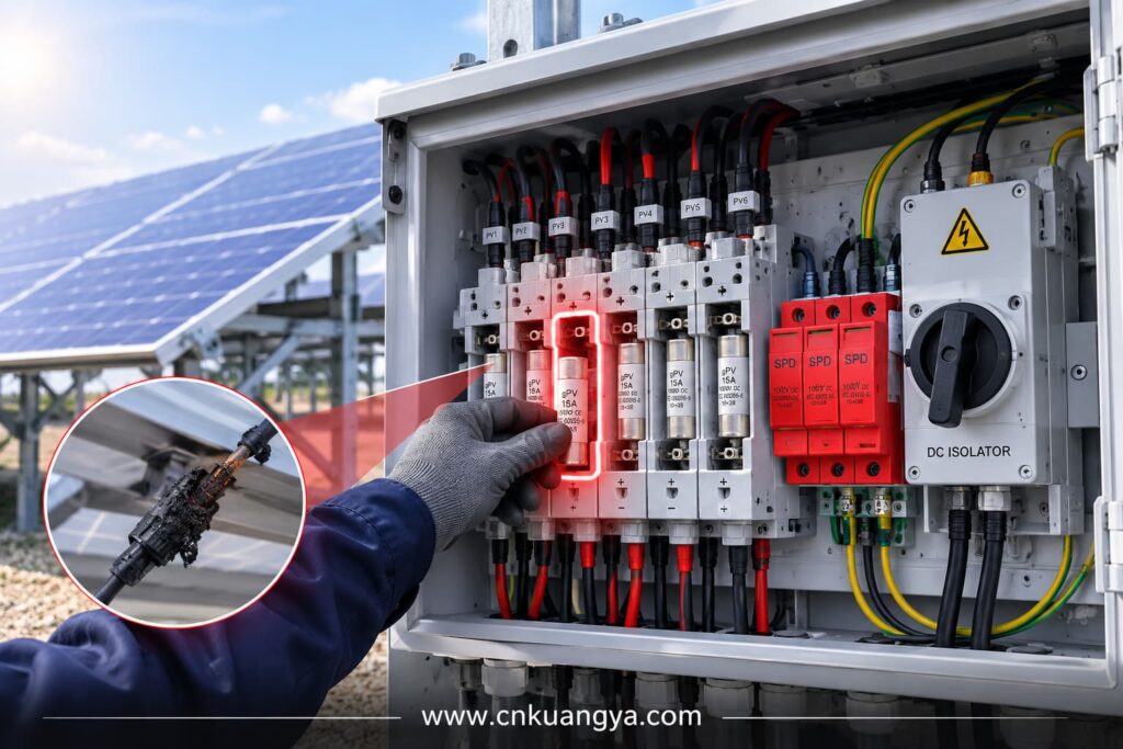
يمكن أن يتجاوز هذا التيار العكسي:
هذا أحد الأسباب الرئيسية لاستخدام مصهرات (فيوزات) gPV في مصفوفات الطاقة الشمسية الكبيرة.
السؤال الهندسي ليس ببساطة:
“ما مقدار التيار الذي تنتجه لوحة شمسية واحدة؟”
السؤال الأكثر أهمية هو:
“ما مقدار تيار العطل الذي يمكن أن توفره السلاسل المتوازية الأخرى إلى سلسلة تالفة واحدة؟”
هذا الفرق هو جوهر التنسيق الصحيح للمصهرات.
غالباً ما تشتمل التركيبات الشمسية على:
These characteristics can increase exposure to transient overvoltages.
A nearby lightning event does not have to strike a solar panel directly to create damaging voltage impulses.
Electromagnetic coupling into long conductors can produce transient overvoltages capable of stressing:
This is why surge protection must be considered as a system design issue rather than simply an optional accessory.
Electrical components in PV systems may be exposed to:
A protection device that is correctly rated electrically can still fail if the installation environment is ignored.
موثوقة الحماية الكهربائية للطاقة الشمسية الكهروضوئية therefore depends on both electrical coordination and suitable environmental design.
A simplified PV protection path can be represented as follows:
الألواح الكهروضوئية
↓
PV Strings
↓
String Protection / gPV Fuses
↓
صندوق التجميع الكهروضوئي
↓
الحماية من زيادة التيار المستمر
↓
DC Isolation
↓
عاكس الطاقة الشمسية
↓
AC Surge and Overcurrent Protection
↓
Distribution System / Grid
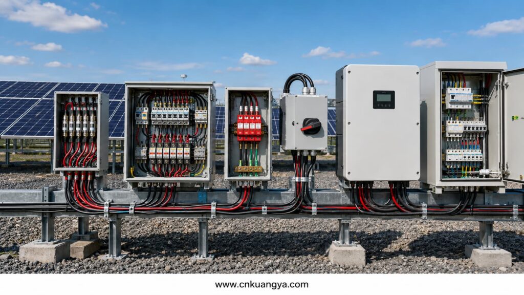
The exact architecture changes according to system size.
For example, a small residential string inverter system may not use a separate external combiner box.
A large commercial or utility-scale plant may include:
The protection principle, however, remains the same.
Every risk should be assigned to the device designed to control it.
| Electrical Risk | Primary Protection Function |
|---|---|
| Reverse string overcurrent | مصهر gPVV |
| Short-circuit or overcurrent | Fuse or suitable protective device |
| Lightning-induced transient | SPD |
| Switching transient | SPD |
| Maintenance disconnection | عازل التيار المستمر |
| Multiple-string collection | صندوق التجميع |
| Localized component fault | Coordinated protection and isolation |
| Inverter input surge | DC-side SPD |
| AC-side surge | AC SPD |
| التعرض البيئي | Suitable enclosure and component ratings |
The most common design problems occur when these functions are confused, especially when engineers fail to distinguish between a DC fuse and DC SPD.
A gPV fuse is specifically intended for photovoltaic applications.
Its purpose is primarily to protect:
against damaging overcurrents under the conditions that can occur in photovoltaic systems.
PV fuse-links are addressed by IEC 60269-6, which provides supplementary requirements for fuse-links used to protect PV strings and arrays in DC circuits up to 1500V.
The designation gPV is important.
A conventional AC fuse should not automatically be substituted for a fuse designed for photovoltaic DC applications.
PV systems can operate under:
The fuse must be designed and tested for the application.
Not every PV string automatically requires a fuse.
The need for string overcurrent protection depends on system design, including:
Consider a system with many parallel strings.
If one string develops a short circuit, the remaining strings may contribute reverse current into the faulted circuit.
The fuse should disconnect the faulted string before the current causes unacceptable thermal damage to cables, connectors or modules.
In a system with only one string, or in some limited parallel configurations, the available reverse current may not justify individual string fusing.
بناءً على ذلك:
The number of PV strings alone should not be used as the only fuse-selection rule.
The engineer must evaluate the possible fault current and the withstand limits of the protected circuit.
A proper gPV fuse selection process should consider at least five parameters.
The fuse voltage rating must be suitable for the maximum possible system voltage.
Common PV fuse voltage classes include:
The selected rating must account for the maximum PV array voltage under expected operating conditions.
Cold weather is particularly important because PV module open-circuit voltage can increase as cell temperature decreases.
A system with a normal operating voltage below 1000V may still experience a higher maximum calculated voltage under low-temperature conditions.
For typical 1000V PV string applications, KUANGYA also provides 10×38 gPV fuse links for solar systems.
The fuse current rating should coordinate with:
Selecting a fuse only because its rated current is slightly above normal operating current is not a sufficient engineering method.
The selected fuse must carry legitimate operating current without nuisance operation while still providing meaningful protection during an abnormal overcurrent condition.
PV module manufacturers generally specify a maximum protective fuse rating or similar limitation.
The selected fuse must not exceed the protection limits established for the module and system design.
A larger fuse may appear to reduce nuisance operation, but oversizing can reduce protection effectiveness.
The fuse must be capable of safely interrupting the available fault current.
Although PV string currents are often lower than industrial short-circuit currents on large AC networks, the breaking capacity should still be verified rather than assumed.
Fuse performance can be influenced by:
A combiner box installed outdoors in a hot climate may experience a much higher internal temperature than the surrounding ambient air.
Protection selection should reflect the actual installation environment.
One common mistake is increasing the fuse rating whenever nuisance operation occurs.
This may hide the actual problem.
Repeated fuse operation can indicate:
Simply installing a larger fuse can allow damaging current to continue for longer.
Correct protection requires investigation, not automatic upsizing.
A surge protective device limits transient overvoltage by diverting surge current away from sensitive equipment.
On the DC side of a PV installation, SPDs may help protect:
IEC 61643-31 covers SPDs intended for the DC side of photovoltaic installations up to 1500V DC, while IEC 61643-32 provides principles for SPD selection, installation and coordination in PV systems.
For an overview of the complete standard family, see our guide to IEC 61643 and Surge Protective Devices.
An SPD is not designed to perform the same function as a fuse.
It does not primarily protect against sustained overcurrent.
It responds to transient overvoltage events.
Transient overvoltages may result from:
A lightning strike near a PV installation can induce a surge into long DC conductors through electromagnetic coupling.
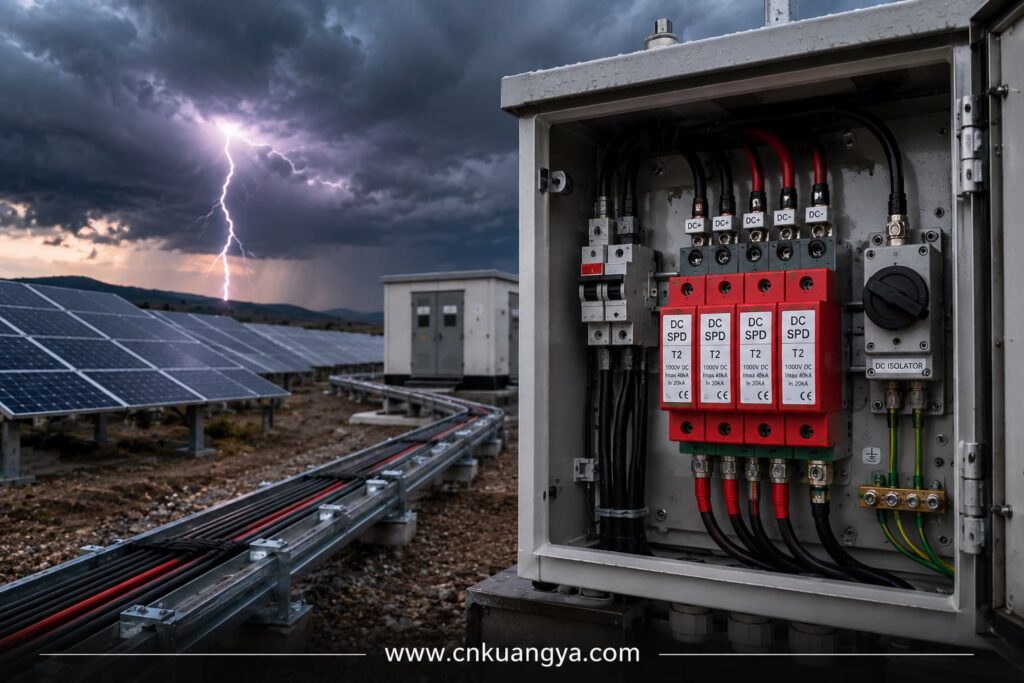
Systems exposed to direct lightning effects require a broader lightning protection assessment and appropriate coordination between the external lightning protection system and electrical SPDs.
Switching operations within electrical networks can also create transient overvoltages.
Long DC cable routes can increase exposure to induced transient energy and create greater separation between protected equipment and the SPD.
A simplified distinction is:
Used where the installation must manage partial lightning current or where the lightning protection design requires Type 1 capability.
Used primarily to protect against induced and switching overvoltages.
Many PV installations use Type 2 DC SPDs where the risk assessment and system design do not require Type 1 capability.
However, device type should not be selected only by habit.
يعتمد الاختيار الصحيح على:
The SPD must withstand the maximum expected DC voltage of the PV array without entering an unsafe operating condition.
An SPD should not be selected only because its label says “solar.”
Its voltage characteristics must match the system.
Engineers working with 600V to 1500V photovoltaic systems can also review KUANGYA’s Type 2 PV surge protective device for typical DC-side protection applications.
The SPD should limit the transient voltage to a level compatible with the withstand capability of downstream equipment.
Protection coordination matters.
An SPD with an unsuitable protection level may not provide the intended protection to sensitive inverter electronics.
This parameter indicates the SPD’s capability under standardized surge-current conditions.
It should be selected according to the expected surge environment and system design.
Depending on SPD type, the device may be characterized for different surge waveforms and current capabilities.
Engineers should compare actual standardized parameters rather than selecting products solely on marketing descriptions such as “heavy duty.”
The required SPD configuration depends on the PV system topology and earthing arrangement.
Common PV SPD configurations may include different numbers of poles or protective paths.
The system topology must be understood before the SPD is selected.
A correctly selected SPD can still provide poor protection if it is installed incorrectly.
تشمل العوامل المهمة ما يلي:
Long connecting conductors introduce additional inductive voltage during fast surge events.
As a practical engineering principle:
Keep SPD connection paths as short and direct as the installation permits.
When the PV array and inverter are separated by a long cable distance, a single SPD at only one end may not always provide the desired protection for both ends.
The system should be evaluated as a complete electrical path.
A DC isolator provides a means of disconnecting part of the PV DC circuit.
It supports:
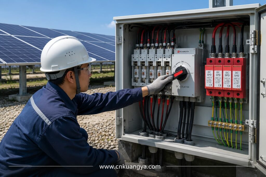
A DC isolator does لا automatically replace:
Its primary function is isolation.
This distinction is essential.
High-voltage DC switching can produce sustained electrical arcs.
A DC isolator used in a PV system must therefore be suitable for:
Using an AC-rated switch in a high-voltage DC application can be extremely dangerous.
The physical appearance of two switches may be similar, while their internal switching capability is very different.
A high-resistance connection creates localized heating.
Over time, thermal cycling can worsen the connection and damage:
An isolator rated for a lower DC voltage may fail to interrupt the circuit safely.
Some multi-pole DC isolators depend on a specific pole arrangement to achieve their intended voltage rating.
Incorrect connection can reduce switching capability.
Outdoor isolators may fail because of:
PV systems operate through daily heating and cooling cycles.
Mechanical connections that were initially acceptable can deteriorate if installation quality is poor.
The appropriate location depends on the system architecture.
Possible locations include:
The objective is to provide practical and safe isolation of the relevant circuit section.
A disconnect that is technically present but difficult to access during maintenance may provide limited operational value.
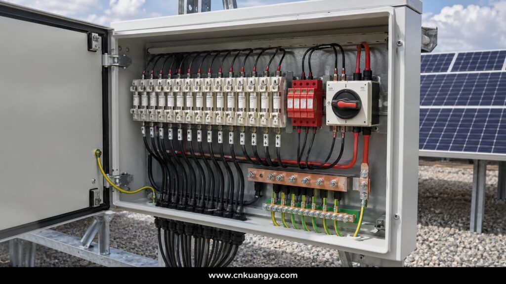
A صندوق التجميع الكهروضوئي collects the outputs of multiple strings and combines them into one or more larger DC output circuits.
Depending on the design, it may include:
The combiner box therefore sits at one of the most important coordination points in the PV DC system.
A common purchasing mistake is comparing combiner boxes mainly by:
The actual engineering quality depends on what is inside.
Important questions include:
A high IP rating alone does not guarantee electrical safety.
The fuse and SPD have fundamentally different jobs.
Responds to sustained abnormal overcurrent.
Responds to short-duration transient overvoltage.
أثناء التشغيل العادي:
During an overcurrent fault:
During a surge event:
This is why describing an SPD as a “surge fuse” is technically misleading.
The two devices should be coordinated but should never be treated as interchangeable, and their position within a solar combiner box wiring diagram should reflect their different protection functions.
A combiner box may contain many current-carrying components in a relatively small enclosure.
Heat can be produced by:
Outdoor solar heating can increase the internal temperature further.
Designers should consider:
Thermal problems often develop gradually.
A connection may operate for months before increasing resistance leads to severe overheating.
الفعالية solar inverter protection is particularly important because the inverter is one of the most valuable and electronically sensitive components in the PV system.
It is also connected to two different electrical environments:
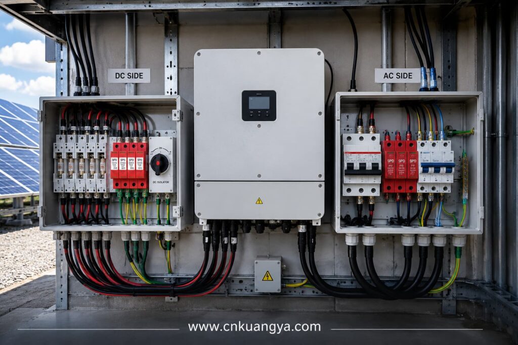
Protection should therefore be considered on both sides.
Potential risks include:
The upstream protection architecture may include:
The exact configuration depends on the inverter design and the PV array architecture.
The AC side may require:
Protecting only the DC side does not create a fully protected inverter.
Surges can reach connected equipment through more than one electrical path.
Modern PV plants may also include:
These circuits should not be ignored when assessing surge pathways.
A system can continue generating electricity while losing critical monitoring or communication capability.
For utility and commercial projects, that can create significant operational problems even when the main inverter remains functional.
This is the central concept of الحماية الكهربائية للطاقة الشمسية الكهروضوئية.
Protection devices should not be selected independently.
They must function as a coordinated system.
Use appropriate:
The goal is to protect the circuit against sustained abnormal current.
Use correctly selected:
The goal is to prevent transient voltage from exceeding equipment withstand capability.
Use:
The goal is to allow safe separation of equipment and circuit sections.
Use properly designed:
The goal is to combine protection functions in an organized and maintainable architecture.
Coordinate upstream protection with:
The goal is not merely to protect individual components.
The goal is to control how the entire system responds to abnormal electrical conditions.
Consider ten parallel PV strings connected to one combiner box.
One string develops a serious electrical fault.
Possible sequence:
The SPD does not perform the primary isolation function in this event.
The DC isolator does not automatically trip like a fuse.
Each device has a separate role.
Now consider a nearby lightning event.
Possible sequence:
The gPV fuse may not operate because the event is not simply a sustained string overcurrent.
Again, the correct protection depends on the correct device.
As PV plants move from 1000V to 1500V systems, protection-device coordination becomes increasingly important in large commercial and utility-scale projects.
Higher DC voltage can reduce current for a given power level and may reduce certain balance-of-system requirements.
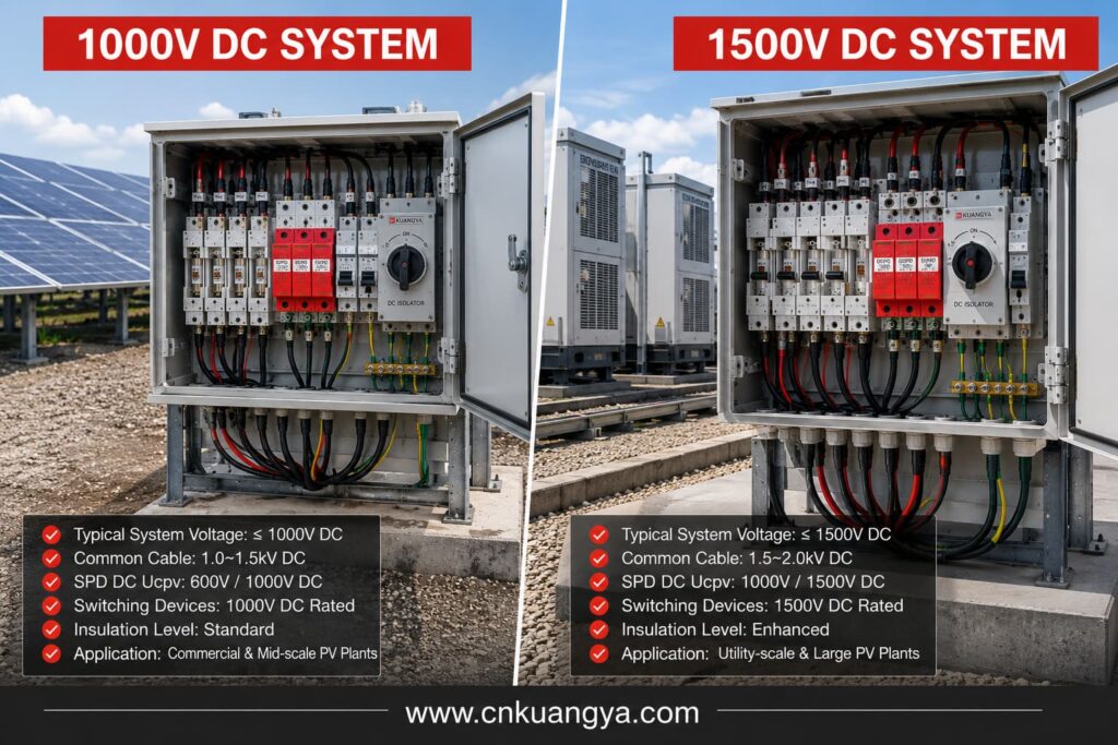
However, increasing system voltage also increases protection demands.
For a 1500V DC system, engineers must verify that all applicable components are suitable for the required voltage.
This may include:
A 1500V SPD does not make a combiner box a 1500V system if another internal component is rated for only 1000V.
The complete assembly is limited by its weakest relevant component.
Higher voltage places greater demands on:
Pollution and moisture can further influence insulation performance.
Interrupting a high-voltage DC circuit requires equipment designed for that duty.
The correct isolator or breaker should be selected according to the actual circuit configuration.
PV module voltage increases when module temperature decreases.
Designers should calculate the maximum array open-circuit voltage under the minimum expected temperature conditions.
Using only the module’s standard test condition voltage can lead to an underspecified protection system.
Many inverters include internal protective functions.
However, internal protection does not automatically eliminate the need for external:
The full system architecture must be evaluated.
An AC fuse should not be assumed suitable for high-voltage DC interruption.
Use a fuse specifically designed and rated for the PV application.
System voltage is only one parameter.
Engineers should also review:
Long conductors can reduce effective surge protection.
Connection paths should be designed to be short and direct.
An isolator and an overcurrent protective device are not automatically the same thing.
The device function must match the protection requirement.
A larger fuse may reduce protection.
The cause of repeated fuse operation should be investigated.
High internal temperature can affect:
Thermal design should be evaluated under realistic outdoor conditions.
One lower-rated component can compromise the entire high-voltage assembly.
The inverter is connected to both DC and AC electrical systems.
A complete protection assessment should consider both.
Large PV systems should have a clear protection architecture showing:
Protection should be designed as a system rather than purchased as a collection of unrelated products.
A structured engineering workflow reduces selection errors.
Record:
Consider:
Verify that the result remains within the rating of every relevant DC component.
Determine:
Decide whether individual string fusing is required.
تحقق من ذلك:
Evaluate:
Then select the appropriate SPD type and ratings.
Determine where safe disconnection is required for:
Select appropriately rated DC isolators.
Coordinate:
Check:
Do not stop at the inverter DC terminals.
Evaluate:
Before commissioning, confirm that no component creates a weak point.
This final system-level review is what transforms individual devices into coordinated الحماية الكهربائية للطاقة الشمسية الكهروضوئية.
Protection devices require inspection throughout the life of the PV installation.
ابحث عن:
Check:
SPDs can degrade after repeated surge exposure.
Check for:
ابحث عن:
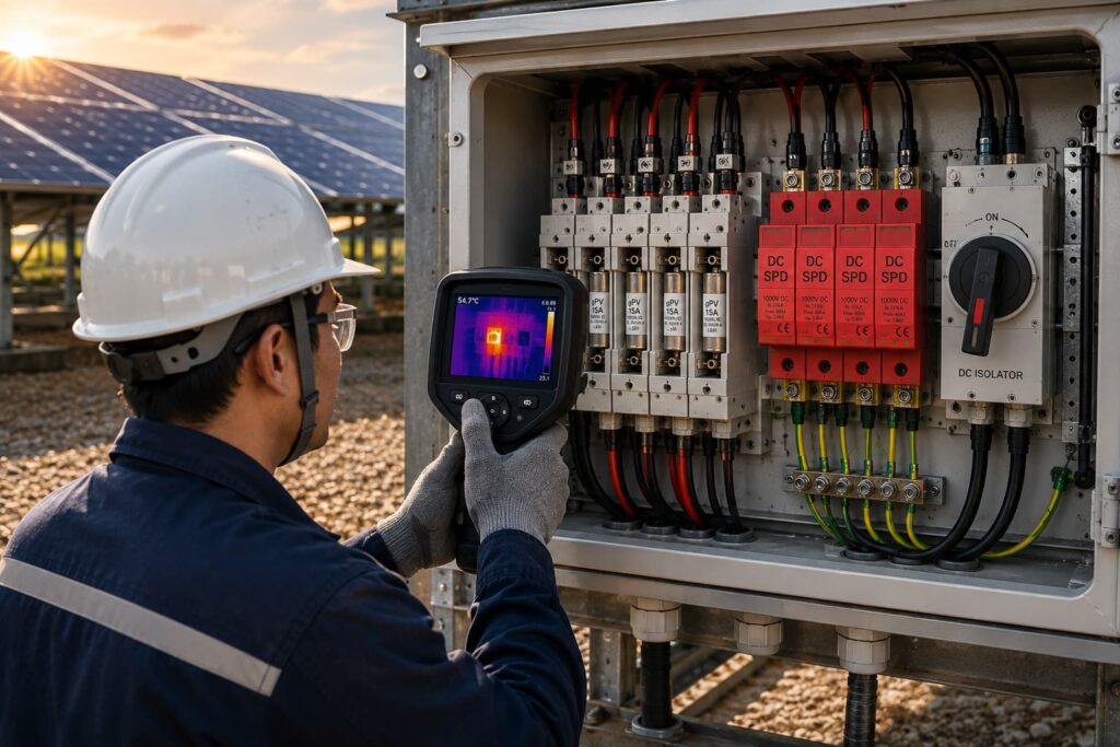
Thermal imaging can be useful for identifying developing high-resistance connections in operating equipment.
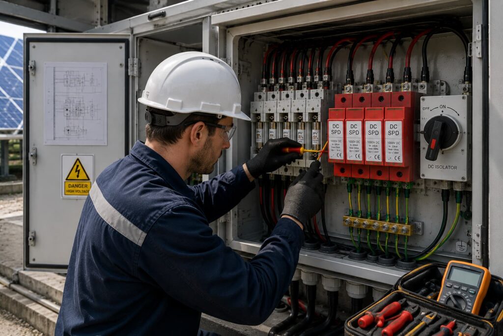
Before approving a PV protection design, verify the following.
Solar PV Electrical Protection is the coordinated use of fuses, SPDs, isolators, breakers, combiner boxes and other protective measures to reduce electrical risks throughout a photovoltaic system.
لا يوجد.
The requirement depends on the number of parallel strings, possible reverse current, conductor ratings, module limitations and applicable design rules.
The fault-current scenario should be evaluated rather than assuming that every string always requires a fuse.
Sometimes a correctly selected PV DC circuit breaker may perform an overcurrent protection function, but devices are not automatically interchangeable.
The correct solution depends on:
لا يوجد.
An SPD protects mainly against transient overvoltage.
A fuse protects against sustained abnormal overcurrent.
They perform different functions.
A fuse is not the primary protective device for transient overvoltage.
An appropriately selected SPD is used for surge protection.
A DC isolator primarily provides safe disconnection.
A circuit breaker may provide switching and protective functions depending on its design and ratings.
The terms should not be used interchangeably without checking the actual device function.
Possible locations include:
The correct arrangement depends on cable length, system architecture and surge protection design.
ليس دائماً.
Long cable distances, multiple system zones and exposure conditions may require protection at more than one location.
The complete surge path should be evaluated.
The SPD must be selected according to the actual maximum PV system voltage and its required electrical characteristics.
A 1500V system requires components suitable for the relevant maximum voltage, but simply choosing the highest voltage label is not automatically the best protection strategy.
A PV combiner box combines the outputs of multiple PV strings and may integrate:
لا يوجد.
Ingress protection is important, but electrical safety also depends on:
Depending on the project and jurisdiction, important references may include:
The applicable edition, national adoption and local electrical regulations should always be confirmed for the specific project.
موثوقة الحماية الكهربائية للطاقة الشمسية الكهروضوئية is not achieved by adding more protective devices without a system plan.
It is achieved by giving every device a clearly defined responsibility.
استخدم مصهر gPVV to address appropriate overcurrent and reverse-current risks.
استخدم DC SPD to limit transient overvoltages.
استخدم عازل التيار المستمر to provide safe electrical disconnection.
استخدم صندوق التجميع الكهروضوئي to integrate string collection and protection in a controlled electrical environment.
Then coordinate all of these elements with the inverter, cables, PV modules, AC system and project operating conditions.
The most important design question should never be:
“Which protection product should we add?”
The better question is:
“What electrical failure are we trying to control, which device is responsible for controlling it, and how does that device coordinate with the rest of the PV system?”
That system-level approach is the foundation of effective الحماية الكهربائية للطاقة الشمسية الكهروضوئية.
For modern 1000V and 1500V photovoltaic projects, protection coordination becomes increasingly important as system voltage, power density and equipment value increase.
A well-designed PV system should therefore treat protection as an integrated architecture:
Detect the risk.
Limit the fault.
Isolate the affected circuit.
Protect critical equipment.
Maintain safe operation.
That is the difference between installing individual protective components and engineering a complete solar PV electrical protection system.

