منطقة ونغ يانغ الصناعية يويتشينغ ونتشو 325000
ساعات العمل
من الاثنين إلى الجمعة: 7 صباحاً - 7 مساءً
عطلة نهاية الأسبوع 10 صباحاً - 5 مساءً
منطقة ونغ يانغ الصناعية يويتشينغ ونتشو 325000
ساعات العمل
من الاثنين إلى الجمعة: 7 صباحاً - 7 مساءً
عطلة نهاية الأسبوع 10 صباحاً - 5 مساءً

آخر تحديث: 17 يوليو 2026 | الإصدار 1.1
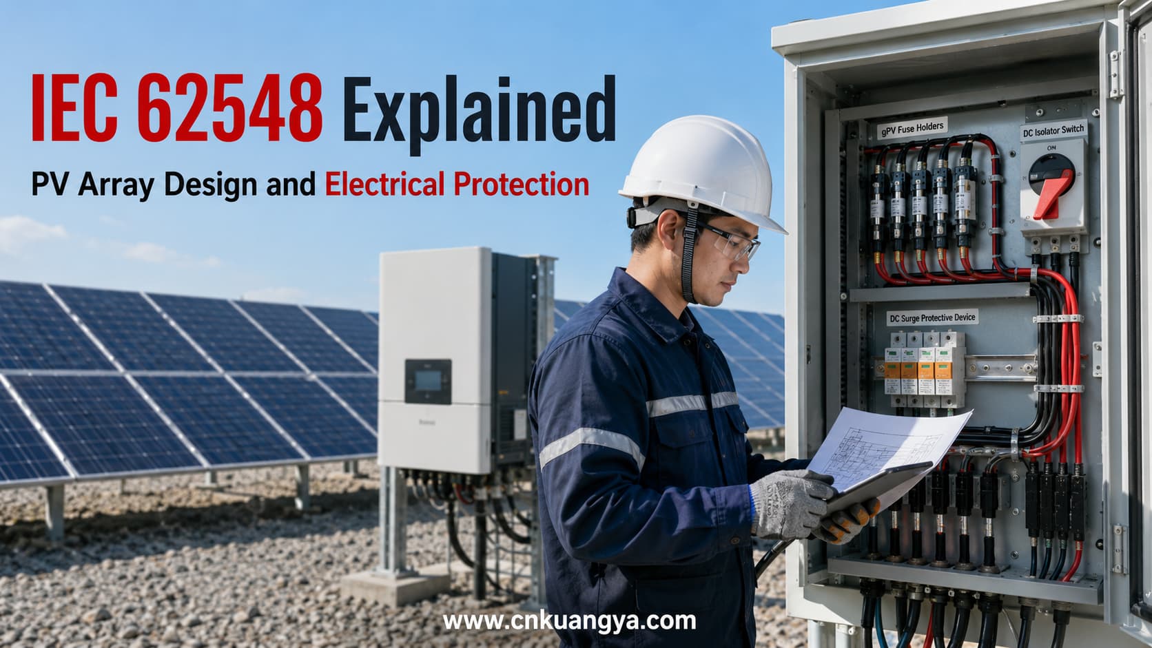
يعد معيار IEC 62548 مرجعاً دولياً رئيسياً لتصميم مصفوفات الطاقة الشمسية الكهروضوئية.
الإصدار الأساسي الحالي هو IEC 62548-1:2023, ، مع التعديل رقم 1 الذي نُشر في عام 2025.
من الناحية الهندسية العملية، يتناول معيار IEC 62548 موضوعات رئيسية في تصميم مصفوفات الطاقة الشمسية الكهروضوئية تشمل:
المبدأ الأكثر أهمية بسيط:
يجب تصميم مصفوفة الخلايا الكهروضوئية لتتحمل أقصى ظروف كهربائية وبيئية ممكنة، وليس فقط قيم التشغيل العادية.
يجب على المهندسين مراعاة جهد الدائرة المفتوحة في الطقس البارد، والتيار العكسي من التوصيلات المتوازية، وقدرة التبديل للتيار المستمر، وحالة الكابلات، وتنسيق الحماية.
يجب بالتالي التعامل مع معيار IEC 62548 كإطار عمل لتصميم المصفوفات الكهروضوئية (PV) وليس كقائمة مراجعة للمنتجات.
يشرح هذا الدليل المعيار بمصطلحات هندسية عملية.
IEC 62548 يُستخدم بشكل شائع عند مناقشة التصميم الكهربائي وسلامة المصفوفات الكهروضوئية.
الإصدار الحالي يحمل العنوان:
IEC 62548-1: المصفوفات الكهروضوئية (PV) – الجزء 1: متطلبات التصميم
يتناول المعيار مخاطر التصميم الناتجة عن الخصائص المحددة لأنظمة التيار المستمر الكهروضوئية.
تختلف المصفوفات الكهروضوئية عن الدوائر الكهربائية التقليدية لأنها قد:
تؤثر هذه الخصائص على اختيار:
يوفر المعيار IEC 62548 إطار عمل على مستوى النظام لمعالجة هذه القضايا.
لا تقتصر قيمته على مجرد تحديد المنتجات المتوافقة.
يساعد المعيار المهندسين على فهم كيفية تصميم مصفوفة الطاقة الشمسية الكهروضوئية بالكامل ضمن إطار منسق. نظام الحماية الكهربائية للطاقة الشمسية الكهروضوئية..
لا تزال العديد من المقالات التقنية القديمة تشير إلى. IEC 62548:2016..
بالنسبة للأعمال الهندسية الحالية، فإن المنشور الأساسي هو:
المنشور الموحد الحالي هو IEC 62548-1:2023+AMD1:2025.
المصطلح العام IEC 62548 لا يزال مستخدماً على نطاق واسع في الصناعة وعمليات البحث عبر الإنترنت.
ومع ذلك، يجب أن تحدد الوثائق الفنية الإصدار الفعلي المستخدم في المشروع.
وهذا مهم بشكل خاص في:
يجب على المهندسين أيضاً التحقق مما إذا كان المشروع يستخدم اعتماداً وطنياً أو إقليمياً لمعيار IEC.
بيان عام مثل:
مصمم وفقاً للمعيار IEC 62548
قد يكون أقل دقة من تحديد الإصدار ذي الصلة والمعيار المعتمد.
يركز المعيار IEC 62548-1 بشكل أساسي على تصميم المصفوفات الكهروضوئية.
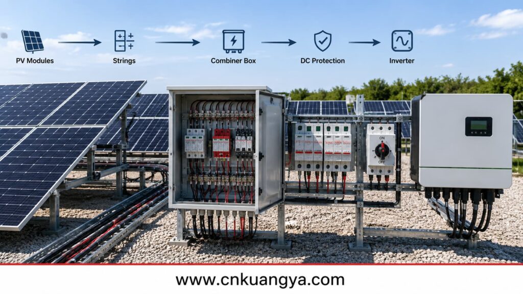
يشمل نطاقه موضوعات رئيسية مثل:
من الناحية العملية للنظام، يتبع المعيار مسار المصفوفة الكهروضوئية وصولاً إلى معدات تحويل الطاقة النهائية، والتي عادة ما تكون العاكس (Inverter).
لا ينبغي افتراض أنه يغطي كل نظام فرعي في مشاريع الطاقة الشمسية.
على سبيل المثال، تطرح أنظمة تخزين الطاقة بالبطاريات قضايا منفصلة مثل:
يجب أيضاً تنسيق متطلبات تركيب الأنظمة الكهروضوئية الأوسع مع IEC 60364-7-712:2025 والقواعد الكهربائية الوطنية المعمول بها.
يؤدي هذا إلى مبدأ هندسي هام:
لا ينبغي توقع أن يحدد معيار IEC واحد كل متطلبات الحماية لمحطة طاقة شمسية بأكملها.
يتناول معيار IEC 62548 في المقام الأول طبقة تصميم المصفوفة الكهروضوئية.
توفر معايير أخرى متطلبات أكثر تفصيلاً لمعدات محددة أو وظائف تركيب معينة.
يُعد أقصى جهد للخلايا الكهروضوئية أحد أوائل معايير التصميم التي يجب تحديدها.
جهد التشغيل الطبيعي لنظام تتبع نقطة القدرة القصوى (MPPT) في العاكس ليس هو نفسه أقصى جهد يمكن أن تنتجه مصفوفة الخلايا الكهروضوئية.
يعتمد أقصى جهد للتصميم على عوامل تشمل:
Cold weather is particularly important.
As module temperature decreases, open-circuit voltage generally increases.
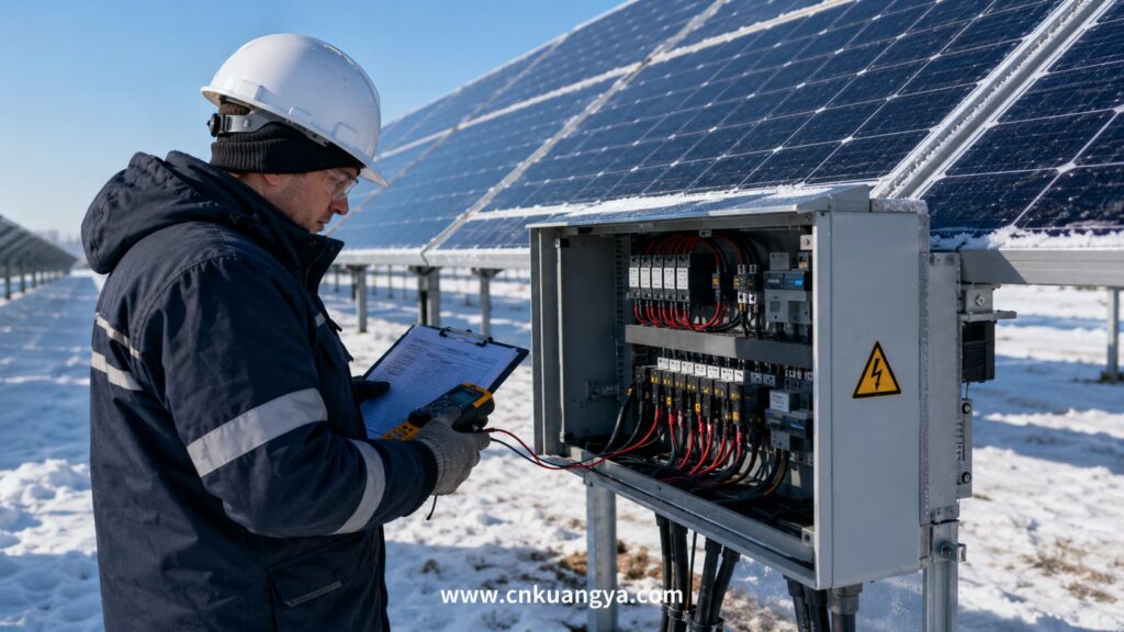
A string that appears acceptable under standard test conditions may exceed a device voltage limit under cold operating conditions.
The maximum voltage assessment affects:
A system described as “1500V DC” is not automatically suitable for 1500V operation simply because the inverter or SPD carries a 1500V rating.
Every relevant component in the DC path must be suitable for the calculated conditions.
The complete electrical path must be reviewed, not only the main equipment.
Series-connected modules primarily influence voltage.
Parallel-connected strings significantly affect current and fault conditions.
The engineer should review module data including:
However, normal operating current does not fully describe the fault condition.
Consider one PV string operating independently.
Its available current is limited by the electrical characteristics of that string.
Now consider multiple strings connected in parallel.
If one string develops a fault, healthy strings may contribute reverse current toward the damaged circuit.
The designer should assess whether this current could exceed the safe limits of:
This analysis directly affects the need for string overcurrent protection.
More parallel strings do not simply mean that a larger fuse should be installed.
The fault architecture must be evaluated.
Overcurrent protection is one of the most important areas of PV array design.
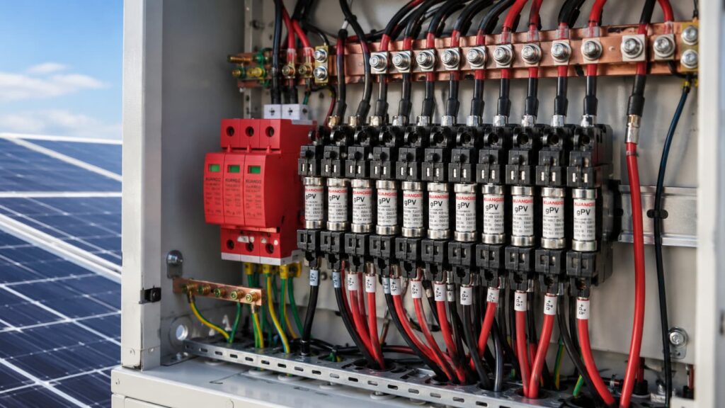
A gPV fuse is designed for photovoltaic DC circuit protection.
PV fuse-links for string and array protection are specifically addressed by IEC 60269-6.
PV circuits can involve:
These operating conditions differ from many conventional AC applications.
Understanding the difference between a gPV fuse and a standard fuse is important because ordinary AC fuses should not automatically be used as substitutes in PV DC circuits.
لا يوجد.
The need for string protection depends on factors such as:
The correct process is:
Analyze the fault condition first. Select the protective device second.
A gPV fuse review should include:
The fuse and fuse holder must be suitable for the maximum relevant DC voltage.
The fuse should carry normal PV operating current without nuisance operation while still protecting the circuit during abnormal overcurrent.
The module manufacturer’s protection limits should be checked.
The device must be capable of interrupting the applicable fault current.
Fuse behavior can be influenced by actual enclosure temperature.
A combiner box in direct sunlight may operate at a much higher internal temperature than the outdoor ambient temperature.
A fuse should not be selected independently from the protected circuit.
The protection relationship can be simplified as:
PV Source → Cable → Equipment Limit → Protective Device
The protective device should operate before an unacceptable current condition causes serious damage to the protected circuit.
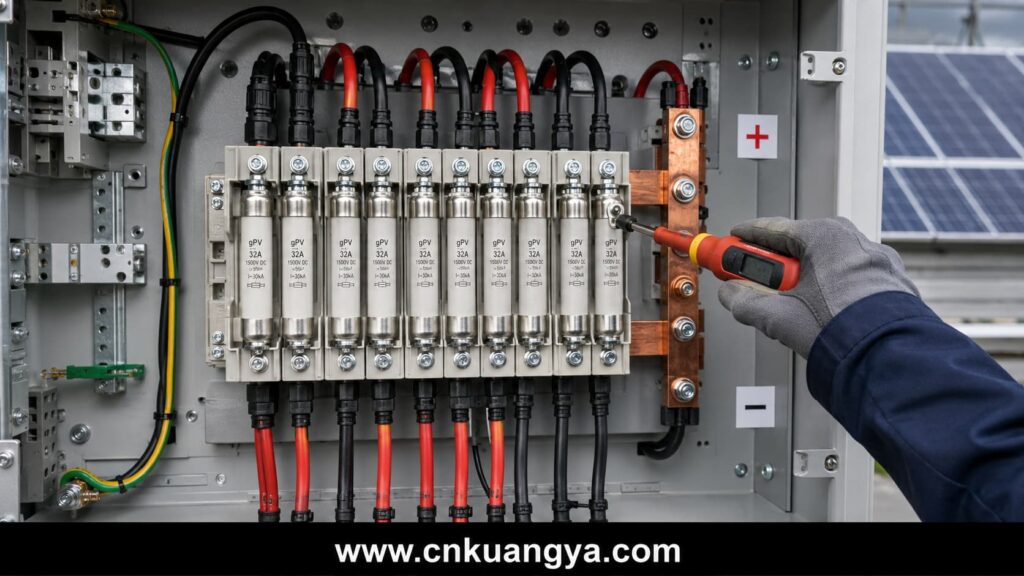
This is why fuse selection is an engineering coordination problem rather than a simple current-rating comparison.
For common 1000V PV string applications, engineers can also review KUANGYA’s 10×38 gPV fuse link for solar systems.
PV cable design is directly related to protection.
A fuse or breaker cannot correct fundamentally incorrect conductor selection.
Cable sizing should consider:
The design should reflect realistic installation conditions.
Cable insulation must be suitable for the maximum PV circuit voltage.
This becomes increasingly important in 1500V DC systems.
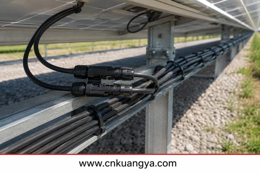
PV cable routing should consider:
Positive and negative conductors should also be routed in a way that avoids unnecessarily large loop areas.
Cable management is not only an installation-quality issue.
It influences long-term electrical reliability.
PV connectors are a common failure point.
Physically mating connectors should not automatically be assumed to be electrically compatible.
Differences in:
may increase contact resistance.
This can lead to:
Connector selection and installation should therefore form part of the PV electrical design review.
Safe isolation is a major requirement in PV array design.
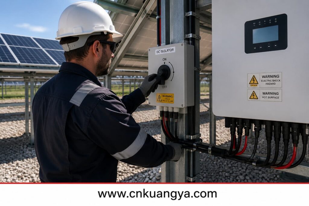
A DC isolator provides a means of separating part of the PV DC circuit.
It may support:
The device must be suitable for the actual PV DC application.
The two devices perform different functions.
A DC isolator primarily provides an isolation function.
An overcurrent protection device responds to abnormal current conditions.
A circuit breaker may provide switching and protective functions according to its design.
Engineers should select the device according to the required function rather than using the terms interchangeably.
PV DC switching is technically demanding because DC current does not have the natural periodic zero crossing found in AC systems.
The designer should verify:
Some multi-pole DC devices require a specific connection arrangement to achieve their intended rating.
Requirements for switches, disconnectors and switch-disconnectors are addressed by IEC 60947-3.
Incorrect wiring may reduce interruption capability.
A disconnect shown on a single-line diagram may still be poorly positioned in the actual installation.
Engineers should ask:
These factors should be evaluated together during اختيار مفتاح الفصل للتيار المستمر (DC), rather than checking voltage and current labels independently.
Safe isolation is both an electrical and operational design issue.
PV arrays may include extensive conductive structures such as:
The earthing and bonding strategy should be coordinated with:
Where protective bonding is required, the continuity of the bonding path should be maintained throughout the life of the installation.
Potential long-term problems include:
A good earthing arrangement does not eliminate the need for correctly selected SPDs.
Similarly, an SPD does not correct a poor bonding system.
These functions interact but are not interchangeable.
PV arrays often include long outdoor conductors.
These conductors can be exposed to transient overvoltages caused by:
IEC 62548 should be used together with more specific SPD standards where detailed surge protection design is required.
The IEC 61643 series includes:
For a wider explanation of the standard family, SPD classifications and selection parameters, read our complete IEC 61643 surge protective device guide.
Important selection parameters may include:
Selecting a product simply because it is described as a “solar SPD” is not sufficient.
SPD performance depends partly on installation.
Long connection conductors can add additional voltage during a fast transient event.
Connection paths should therefore be kept appropriately short and direct.
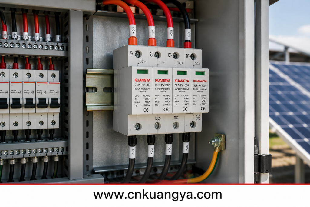
Long cable distances between the PV array, combiner equipment and inverter may also require protection at more than one location.
Surge protection should be evaluated across the complete electrical path.
For 600V to 1500V photovoltaic applications, KUANGYA provides a Type 2 PV surge protective device for combiner boxes, inverter DC inputs and PV distribution cabinets.
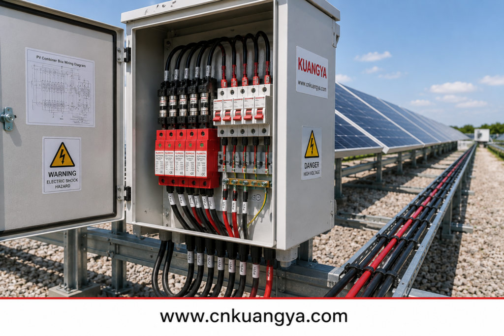
إن صندوق التجميع الكهروضوئي is a major coordination point in multi-string systems.
It may include:
The combiner box should reflect the overall PV array protection strategy.
مراجعة:
The combined output may carry significantly more current than one individual string.
The designer should verify:
Heat can be produced by:
Solar radiation can further increase enclosure temperature.
Component ratings and derating should reflect the actual internal operating environment.
A high ingress-protection rating is important, but it does not prove that a combiner box has been correctly designed.
Electrical safety also depends on:
The complete assembly should be evaluated.
الفعالية solar inverter protection requires the PV array voltage, current and external protection architecture to coordinate with the inverter or other power conversion equipment.
Important inverter parameters may include:
The MPPT range describes the inverter’s normal operating range.
It is not the same as the maximum permissible DC input voltage.
Cold-weather open-circuit voltage must be checked separately.
Modern PV modules may have relatively high operating and short-circuit currents.
A string arrangement can be acceptable from a voltage perspective while exceeding the inverter’s current limitations.
Both voltage and current must be reviewed.
Some inverters include:
These functions should be checked against actual manufacturer documentation.
Do not assume every inverter provides the same internal protection architecture.
Documentation, commissioning tests and inspection for grid-connected PV systems are addressed more specifically by IEC 62446-1.
Correct design does not eliminate installation errors.
Documentation, commissioning and inspection are therefore essential.
Important system documentation may include:
Documentation should match the installed system.
Inspection should look for:
The objective is to verify both electrical design and installation quality.
Many PV electrical failures develop gradually.
وتشمل الأمثلة على ذلك:
Preventive, corrective and performance-related maintenance practices are addressed by IEC 62446-2.
Periodic inspection can help identify problems before they become major failures.
The project should identify the applicable publication and edition.
Cold-weather open-circuit voltage must be evaluated.
String protection should reflect the actual fault architecture.
Voltage, module limitations and installation conditions also matter.
The device must be suitable for the actual DC switching duty.
Voltage rating alone does not define complete suitability.
Cable length affects voltage drop, surge exposure and mechanical design.
Internal protection must be reviewed against the external array design.
Current rating, thermal design and protection coordination also matter.
Individually compliant components do not automatically create a correctly coordinated PV array.
A practical PV array design workflow can be organized into eight steps.
Record:
Determine:
Consider project temperature conditions and module characteristics.
Check all relevant DC equipment.
مراجعة:
Assess whether string protection is required.
Select appropriately rated gPV fuses or other protective devices.
مراجعة:
Coordinate:
صحيح DC fuse and DC SPD coordination is essential because overcurrent protection and transient overvoltage protection address different fault conditions.
مراجعة:
PV Module → String → Cable → Protection → Combiner → Isolation → Inverter
No component should be evaluated independently from the surrounding circuit.
IEC 62548 is commonly used to refer to the international design requirements for photovoltaic arrays.
The current core publication is IEC 62548-1.
The current core edition is IEC 62548-1:2023, with Amendment 1 published in 2025.
The applicable edition and national adoption should be verified for each project.
The main scope focuses on PV array design.
Battery energy storage requires additional standards and system-specific protection assessment.
لا يوجد.
The need for string overcurrent protection depends on parallel-string configuration, reverse current and the electrical limits of the circuit.
IEC 62548-1 focuses on PV array design.
IEC 60364-7-712 addresses electrical installation requirements associated with PV power supply installations.
They are related but not interchangeable.
It addresses PV electrical protection at the array design level.
Detailed PV SPD requirements and selection principles are addressed more specifically by IEC 61643-31 and IEC 61643-32.
Only if the device is specifically suitable and rated for the actual DC voltage, current and switching duty.
An AC rating alone does not demonstrate suitability for PV DC use.
لا يوجد.
Its design principles apply to PV array design more broadly.
However, 1500V systems require particularly careful review of voltage ratings, insulation and DC switching.
لا يوجد.
The complete assembly must be reviewed for:
IEC 62548 should not be treated as a list of protection devices that must be installed in every photovoltaic system.
Its real engineering value is in system-level design.
Start with the PV module.
Define the string configuration.
Calculate the maximum voltage.
Evaluate current and reverse-current conditions.
Then coordinate:
Every protection device should address a specific electrical risk.
A gPV fuse should be selected because an overcurrent condition has been identified.
An SPD should be selected because surge risk has been evaluated.
A DC isolator should provide a clearly defined isolation function.
A combiner box should integrate multiple circuits without creating thermal or coordination problems.
The central engineering lesson is:
PV array safety depends on coordinated electrical design, not on selecting protective devices independently.
For modern photovoltaic systems, the complete DC path should always be reviewed:
PV Module → PV String → DC Cable → Overcurrent Protection → Combiner Box → Surge Protection → Isolation → Inverter
That is the practical purpose of IEC 62548.

