WengYang Industrial Zone Yueqing Wenzhou 325000
Work Hours
Monday to Friday: 7AM - 7PM
Weekend: 10AM - 5PM
WengYang Industrial Zone Yueqing Wenzhou 325000
Work Hours
Monday to Friday: 7AM - 7PM
Weekend: 10AM - 5PM

Last Updated: July 17, 2026 | Version 1.1
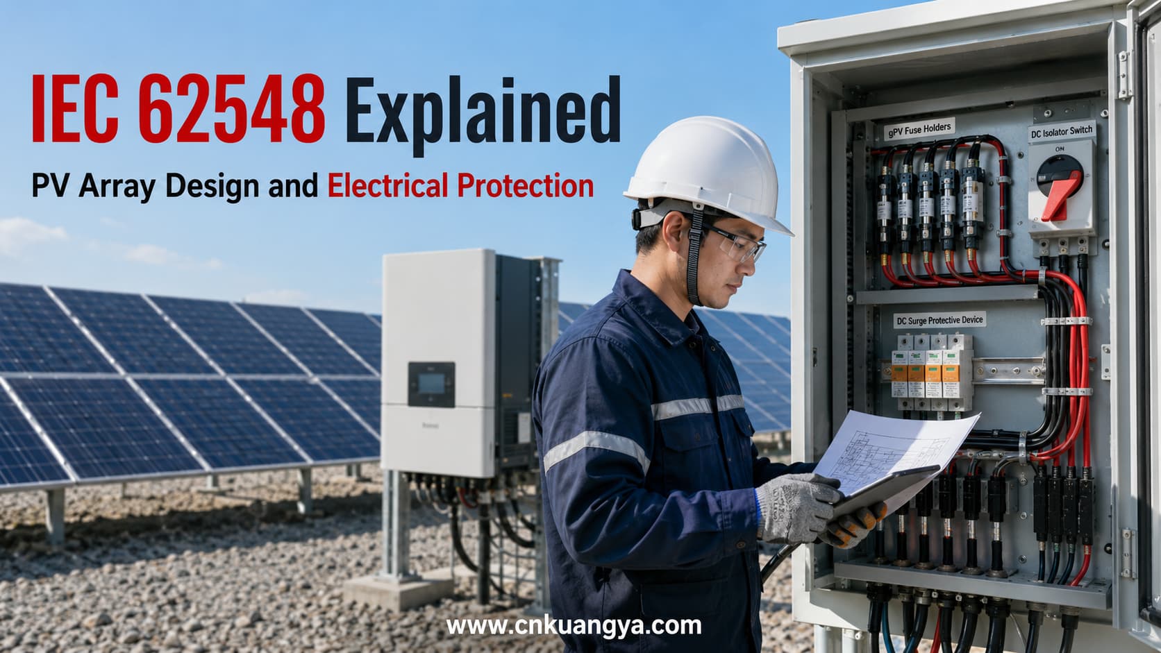
IEC 62548 is a key international reference for photovoltaic array design.
The current core publication is IEC 62548-1:2023, with Amendment 1 published in 2025.
In practical engineering terms, IEC 62548 addresses major PV array design topics including:
The most important principle is simple:
A PV array must be designed for its maximum possible electrical and environmental conditions, not only its normal operating values.
Engineers must consider cold-weather open-circuit voltage, reverse current from parallel strings, DC switching capability, cable conditions and protection coordination.
IEC 62548 should therefore be treated as a PV array design framework rather than a product checklist.
This guide explains the standard in practical engineering terms.
IEC 62548 is commonly used when discussing the electrical design and safety of photovoltaic arrays.
The current publication is titled:
IEC 62548-1: Photovoltaic (PV) arrays – Part 1: Design requirements
The standard addresses design risks created by the specific characteristics of PV DC systems.
Photovoltaic arrays differ from conventional electrical circuits because they may:
These characteristics affect the selection of:
IEC 62548 provides a system-level framework for addressing these issues.
Its value is not simply in identifying compliant products.
The standard helps engineers understand how the entire PV array should be designed within a coordinated Solar PV electrical protection system.
Many older technical articles still refer to IEC 62548:2016.
For current engineering work, the core publication is:
The current consolidated publication is IEC 62548-1:2023+AMD1:2025.
The general term IEC 62548 remains widely used in industry and online searches.
However, technical documentation should identify the actual edition used for a project.
This is especially important in:
Engineers should also verify whether the project uses a national or regional adoption of the IEC standard.
A generic statement such as:
Designed according to IEC 62548
may be less precise than identifying the relevant edition and adopted standard.
IEC 62548-1 focuses primarily on photovoltaic array design.
Its scope includes major subjects such as:
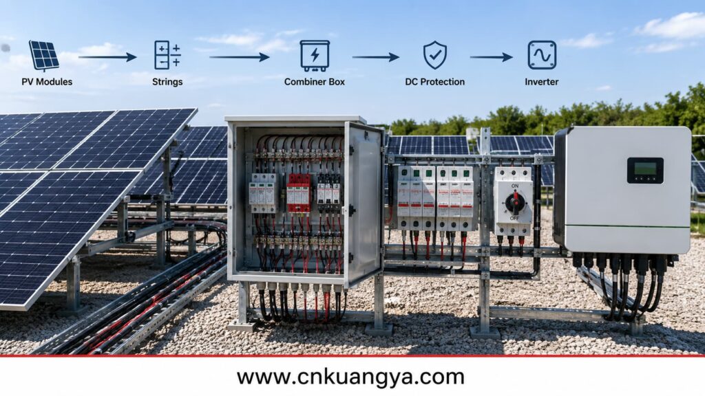
In practical system terms, the standard follows the PV array toward the final power conversion equipment, normally the inverter.
It should not be assumed to cover every subsystem in a solar project.
For example, battery energy storage introduces separate issues such as:
Broader PV installation requirements should also be coordinated with IEC 60364-7-712:2025 and the applicable national electrical rules.
This leads to an important engineering principle:
No single IEC standard should be expected to define every protection requirement for an entire solar power plant.
IEC 62548 primarily addresses the PV array design layer.
Other standards provide more detailed requirements for specific equipment or installation functions.
Maximum PV voltage is one of the first design parameters that should be established.
The normal MPPT operating voltage of an inverter is not the same as the maximum voltage that a PV array can produce.
The maximum design voltage depends on factors including:
Cold weather is particularly important.
As module temperature decreases, open-circuit voltage generally increases.
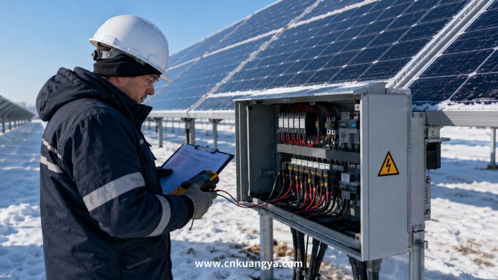
A string that appears acceptable under standard test conditions may exceed a device voltage limit under cold operating conditions.
The maximum voltage assessment affects:
A system described as “1500V DC” is not automatically suitable for 1500V operation simply because the inverter or SPD carries a 1500V rating.
Every relevant component in the DC path must be suitable for the calculated conditions.
The complete electrical path must be reviewed, not only the main equipment.
Series-connected modules primarily influence voltage.
Parallel-connected strings significantly affect current and fault conditions.
The engineer should review module data including:
However, normal operating current does not fully describe the fault condition.
Consider one PV string operating independently.
Its available current is limited by the electrical characteristics of that string.
Now consider multiple strings connected in parallel.
If one string develops a fault, healthy strings may contribute reverse current toward the damaged circuit.
The designer should assess whether this current could exceed the safe limits of:
This analysis directly affects the need for string overcurrent protection.
More parallel strings do not simply mean that a larger fuse should be installed.
The fault architecture must be evaluated.
Overcurrent protection is one of the most important areas of PV array design.
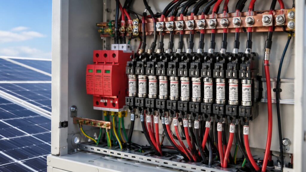
A gPV fuse is designed for photovoltaic DC circuit protection.
PV fuse-links for string and array protection are specifically addressed by IEC 60269-6.
PV circuits can involve:
These operating conditions differ from many conventional AC applications.
Understanding the difference between a gPV fuse and a standard fuse is important because ordinary AC fuses should not automatically be used as substitutes in PV DC circuits.
No.
The need for string protection depends on factors such as:
The correct process is:
Analyze the fault condition first. Select the protective device second.
A gPV fuse review should include:
The fuse and fuse holder must be suitable for the maximum relevant DC voltage.
The fuse should carry normal PV operating current without nuisance operation while still protecting the circuit during abnormal overcurrent.
The module manufacturer’s protection limits should be checked.
The device must be capable of interrupting the applicable fault current.
Fuse behavior can be influenced by actual enclosure temperature.
A combiner box in direct sunlight may operate at a much higher internal temperature than the outdoor ambient temperature.
A fuse should not be selected independently from the protected circuit.
The protection relationship can be simplified as:
PV Source → Cable → Equipment Limit → Protective Device
The protective device should operate before an unacceptable current condition causes serious damage to the protected circuit.
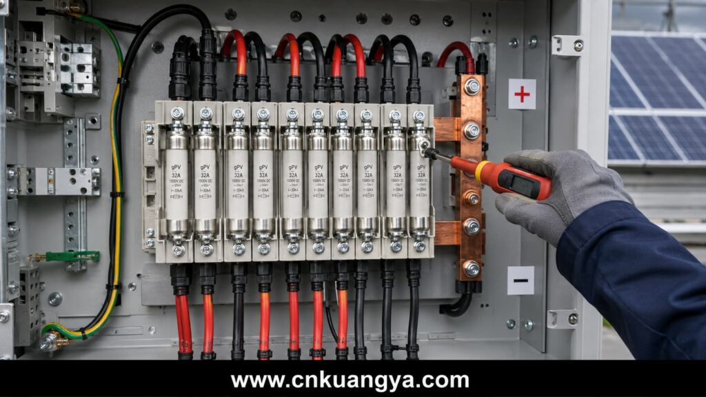
This is why fuse selection is an engineering coordination problem rather than a simple current-rating comparison.
For common 1000V PV string applications, engineers can also review KUANGYA’s 10×38 gPV fuse link for solar systems.
PV cable design is directly related to protection.
A fuse or breaker cannot correct fundamentally incorrect conductor selection.
Cable sizing should consider:
The design should reflect realistic installation conditions.
Cable insulation must be suitable for the maximum PV circuit voltage.
This becomes increasingly important in 1500V DC systems.
PV cable routing should consider:
Positive and negative conductors should also be routed in a way that avoids unnecessarily large loop areas.
Cable management is not only an installation-quality issue.
It influences long-term electrical reliability.
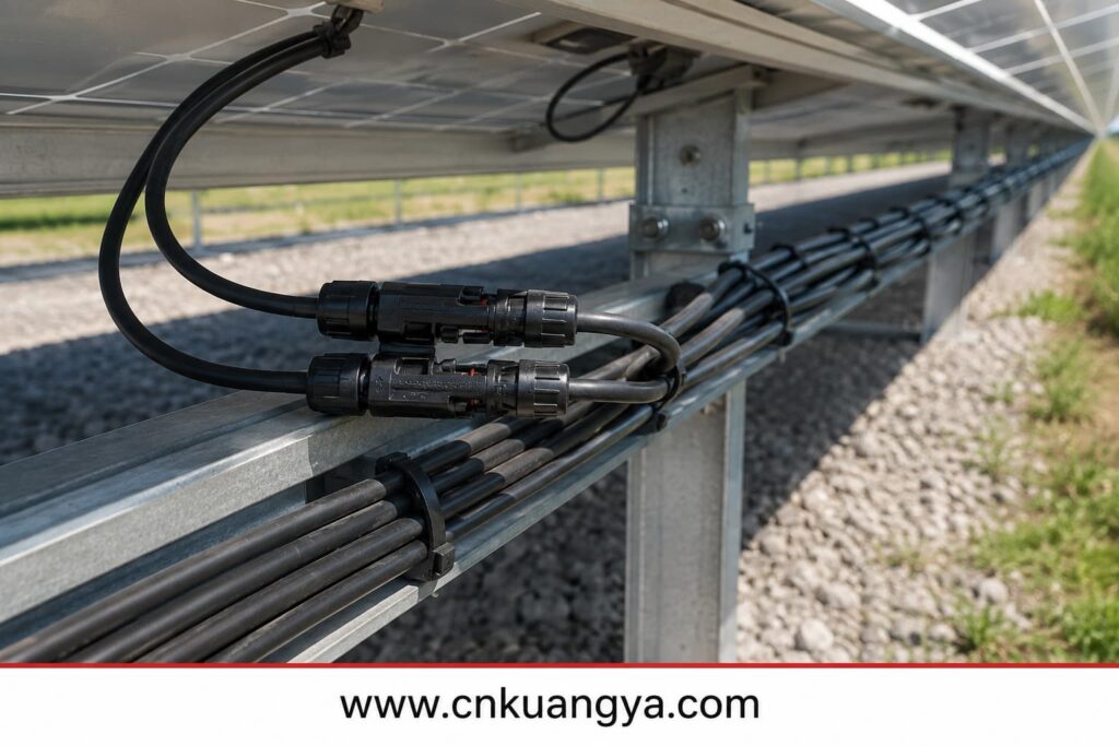
PV connectors are a common failure point.
Physically mating connectors should not automatically be assumed to be electrically compatible.
Differences in:
may increase contact resistance.
This can lead to:
Connector selection and installation should therefore form part of the PV electrical design review.
Safe isolation is a major requirement in PV array design.
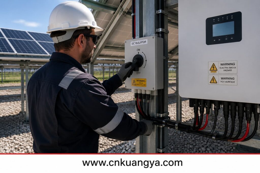
A DC isolator provides a means of separating part of the PV DC circuit.
It may support:
The device must be suitable for the actual PV DC application.
The two devices perform different functions.
A DC isolator primarily provides an isolation function.
An overcurrent protection device responds to abnormal current conditions.
A circuit breaker may provide switching and protective functions according to its design.
Engineers should select the device according to the required function rather than using the terms interchangeably.
PV DC switching is technically demanding because DC current does not have the natural periodic zero crossing found in AC systems.
The designer should verify:
Some multi-pole DC devices require a specific connection arrangement to achieve their intended rating.
Requirements for switches, disconnectors and switch-disconnectors are addressed by IEC 60947-3.
Incorrect wiring may reduce interruption capability.
A disconnect shown on a single-line diagram may still be poorly positioned in the actual installation.
Engineers should ask:
These factors should be evaluated together during DC switch-disconnector selection, rather than checking voltage and current labels independently.
Safe isolation is both an electrical and operational design issue.
PV arrays may include extensive conductive structures such as:
The earthing and bonding strategy should be coordinated with:
Where protective bonding is required, the continuity of the bonding path should be maintained throughout the life of the installation.
Potential long-term problems include:
A good earthing arrangement does not eliminate the need for correctly selected SPDs.
Similarly, an SPD does not correct a poor bonding system.
These functions interact but are not interchangeable.
PV arrays often include long outdoor conductors.
These conductors can be exposed to transient overvoltages caused by:
IEC 62548 should be used together with more specific SPD standards where detailed surge protection design is required.
The IEC 61643 series includes:
For a wider explanation of the standard family, SPD classifications and selection parameters, read our complete IEC 61643 surge protective device guide.
Important selection parameters may include:
Selecting a product simply because it is described as a “solar SPD” is not sufficient.
SPD performance depends partly on installation.
Long connection conductors can add additional voltage during a fast transient event.
Connection paths should therefore be kept appropriately short and direct.
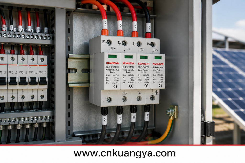
Long cable distances between the PV array, combiner equipment and inverter may also require protection at more than one location.
Surge protection should be evaluated across the complete electrical path.
For 600V to 1500V photovoltaic applications, KUANGYA provides a Type 2 PV surge protective device for combiner boxes, inverter DC inputs and PV distribution cabinets.
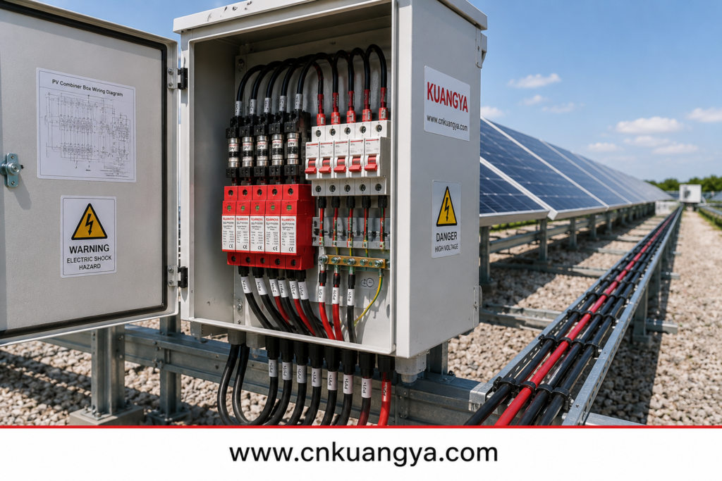
The PV combiner box is a major coordination point in multi-string systems.
It may include:
The combiner box should reflect the overall PV array protection strategy.
Review:
The combined output may carry significantly more current than one individual string.
The designer should verify:
Heat can be produced by:
Solar radiation can further increase enclosure temperature.
Component ratings and derating should reflect the actual internal operating environment.
A high ingress-protection rating is important, but it does not prove that a combiner box has been correctly designed.
Electrical safety also depends on:
The complete assembly should be evaluated.
Effective solar inverter protection requires the PV array voltage, current and external protection architecture to coordinate with the inverter or other power conversion equipment.
Important inverter parameters may include:
The MPPT range describes the inverter’s normal operating range.
It is not the same as the maximum permissible DC input voltage.
Cold-weather open-circuit voltage must be checked separately.
Modern PV modules may have relatively high operating and short-circuit currents.
A string arrangement can be acceptable from a voltage perspective while exceeding the inverter’s current limitations.
Both voltage and current must be reviewed.
Some inverters include:
These functions should be checked against actual manufacturer documentation.
Do not assume every inverter provides the same internal protection architecture.
Documentation, commissioning tests and inspection for grid-connected PV systems are addressed more specifically by IEC 62446-1.
Correct design does not eliminate installation errors.
Documentation, commissioning and inspection are therefore essential.
Important system documentation may include:
Documentation should match the installed system.
Inspection should look for:
The objective is to verify both electrical design and installation quality.
Many PV electrical failures develop gradually.
Examples include:
Preventive, corrective and performance-related maintenance practices are addressed by IEC 62446-2.
Periodic inspection can help identify problems before they become major failures.
The project should identify the applicable publication and edition.
Cold-weather open-circuit voltage must be evaluated.
String protection should reflect the actual fault architecture.
Voltage, module limitations and installation conditions also matter.
The device must be suitable for the actual DC switching duty.
Voltage rating alone does not define complete suitability.
Cable length affects voltage drop, surge exposure and mechanical design.
Internal protection must be reviewed against the external array design.
Current rating, thermal design and protection coordination also matter.
Individually compliant components do not automatically create a correctly coordinated PV array.
A practical PV array design workflow can be organized into eight steps.
Record:
Determine:
Consider project temperature conditions and module characteristics.
Check all relevant DC equipment.
Review:
Assess whether string protection is required.
Select appropriately rated gPV fuses or other protective devices.
Review:
Coordinate:
Correct DC fuse and DC SPD coordination is essential because overcurrent protection and transient overvoltage protection address different fault conditions.
Review:
PV Module → String → Cable → Protection → Combiner → Isolation → Inverter
No component should be evaluated independently from the surrounding circuit.
IEC 62548 is commonly used to refer to the international design requirements for photovoltaic arrays.
The current core publication is IEC 62548-1.
The current core edition is IEC 62548-1:2023, with Amendment 1 published in 2025.
The applicable edition and national adoption should be verified for each project.
The main scope focuses on PV array design.
Battery energy storage requires additional standards and system-specific protection assessment.
No.
The need for string overcurrent protection depends on parallel-string configuration, reverse current and the electrical limits of the circuit.
IEC 62548-1 focuses on PV array design.
IEC 60364-7-712 addresses electrical installation requirements associated with PV power supply installations.
They are related but not interchangeable.
It addresses PV electrical protection at the array design level.
Detailed PV SPD requirements and selection principles are addressed more specifically by IEC 61643-31 and IEC 61643-32.
Only if the device is specifically suitable and rated for the actual DC voltage, current and switching duty.
An AC rating alone does not demonstrate suitability for PV DC use.
No.
Its design principles apply to PV array design more broadly.
However, 1500V systems require particularly careful review of voltage ratings, insulation and DC switching.
No.
The complete assembly must be reviewed for:
IEC 62548 should not be treated as a list of protection devices that must be installed in every photovoltaic system.
Its real engineering value is in system-level design.
Start with the PV module.
Define the string configuration.
Calculate the maximum voltage.
Evaluate current and reverse-current conditions.
Then coordinate:
Every protection device should address a specific electrical risk.
A gPV fuse should be selected because an overcurrent condition has been identified.
An SPD should be selected because surge risk has been evaluated.
A DC isolator should provide a clearly defined isolation function.
A combiner box should integrate multiple circuits without creating thermal or coordination problems.
The central engineering lesson is:
PV array safety depends on coordinated electrical design, not on selecting protective devices independently.
For modern photovoltaic systems, the complete DC path should always be reviewed:
PV Module → PV String → DC Cable → Overcurrent Protection → Combiner Box → Surge Protection → Isolation → Inverter
That is the practical purpose of IEC 62548.

