웽양 공업구 웨칭 원저우 325000
근무 시간
월요일~금요일: 오전 7시~오후 7시
주말: 주말: 오전 10시 - 오후 5시
웽양 공업구 웨칭 원저우 325000
근무 시간
월요일~금요일: 오전 7시~오후 7시
주말: 주말: 오전 10시 - 오후 5시

태양광 발전 시스템은 인근 낙뢰 활동, 스위칭 작업 및 연결된 전기 회로를 통해 전달되는 외란으로 인한 과도 과전압에 노출됩니다. 이러한 현상은 인버터, 모니터링 장비, 접속반 및 기타 민감한 부품을 손상시킬 수 있습니다.
올바른 제품 선택 스페인 태양광 설비용 DC SPD 단순히 공칭 시스템 전압에 장치를 맞추는 것 이상의 고려가 필요합니다. 설계자와 설치자는 최대 태양광 개방 전압, SPD 등급, 방전 용량, 전압 보호 레벨, 시스템 접지 방식, 케이블 거리, 설치 위치 및 적용 표준을 반드시 고려해야 합니다.
그러나 DC SPD를 선택하는 것은 단순히 공칭 시스템 전압에 장치를 맞추는 것 이상의 과정이 필요합니다. 설계자와 설치자는 최대 태양광 개방 전압, SPD 등급, 방전 용량, 전압 보호 레벨, 시스템 접지 방식, 케이블 거리, 설치 위치 및 적용 표준을 반드시 고려해야 합니다.
본 가이드는 스페인 태양광 설비용 DC SPD를 선택하는 방법과 견적 요청 전 확인해야 할 기술 정보를 설명합니다.
태양광 모듈과 연결 케이블은 일반적으로 넓고 노출된 지역에 설치됩니다. 긴 DC 케이블 경로는 낙뢰 유도 및 스위칭 관련 과도 과전압이 인버터에 도달하는 경로가 될 수 있습니다.
서지는 반드시 태양광 어레이에 직접적인 낙뢰가 떨어져서 발생하는 것만은 아닙니다. 인근의 낙뢰가 DC 케이블에 과도 전압을 유도할 수 있으며, 설비 내부의 스위칭 작동 또한 전기적 장애를 일으킬 수 있습니다.
DC SPD의 설계 목적:
SPD는 퓨즈, 차단기, 절연체, 접지 시스템 또는 외부 피뢰 시스템을 대체하지 않습니다. 각 장치는 서로 다른 보호 기능을 수행하며 전체 태양광(PV) 설계의 일부로서 상호 조정되어야 합니다.
스페인의 저압 전기 설비는 일반적으로 REBT로 알려진 저압 전기 규정(Reglamento Electrotécnico para Baja Tensión)의 적용을 받습니다. 적용되는 설계는 현행 기술 지침, 프로젝트 사양, 지역 요구 사항 및 해당 규정에서 참조하는 표준을 고려해야 합니다.
REBT와 관련된 스페인의 공식 표준 목록은 다음과 같습니다:
국제 태양광(PV) 애플리케이션의 경우, 다음 IEC 문서들도 중요합니다:
IEC 61643-31은 정격 전압 최대 1,500V DC인 태양광(PV) 설비의 DC 측에 연결되는 서지 보호 장치(SPD)에 적용됩니다.
프로젝트 요구 사항은 설치 유형, 위험 평가, 위치, 인버터 설계, 외부 피뢰 시스템, 그리고 스페인 당국이나 공인 설치업체의 요구 사항에 따라 다를 수 있습니다. 따라서 제품 선정은 프로젝트 설계자나 자격을 갖춘 전기 전문가가 확인해야 합니다.
첫 번째 선정 매개변수는 PV 시스템용 SPD의 최대 연속 동작 전압이며, 일반적으로 다음과 같이 식별됩니다. Ucpv.
인버터의 공칭 동작 전압만 기준으로 SPD를 선정하지 마십시오.
PV 스트링의 최대 전압은 다음 요소에 따라 달라집니다.
PV 모듈 전압은 온도가 낮아질수록 상승합니다. 따라서 전체 스트링의 최대 저온 조건 개방 전압은 표준 시험 조건에서의 값보다 높을 수 있습니다.
SPD의 Ucpv는 PV 어레이 양단에 지속적으로 발생할 수 있는 최대 전압에 적합해야 합니다.
| PV 시스템 | 일반적인 SPD 전압 등급 | 중요 확인 사항 |
|---|---|---|
| 소규모 주거용 태양광 발전 시스템 | 600V DC | 저온 상태에서의 최대 스트링 개방전압(Voc) 확인 |
| 주거용 또는 상업용 태양광 발전(PV) | 1,000 V DC | 인버터 및 스트링 전압 제한 확인 |
| 상업용 또는 유틸리티급 태양광 발전(PV) | 1,500 V DC | 1,500 V 태양광 시스템 전용으로 설계된 서지 보호 장치(SPD) 사용 |
이는 적용 사례일 뿐이며 자동 선택 규칙이 아닙니다. 최종 SPD 전압은 계산된 최대 태양광 전압과 제조사의 결선도를 기준으로 결정되어야 합니다.
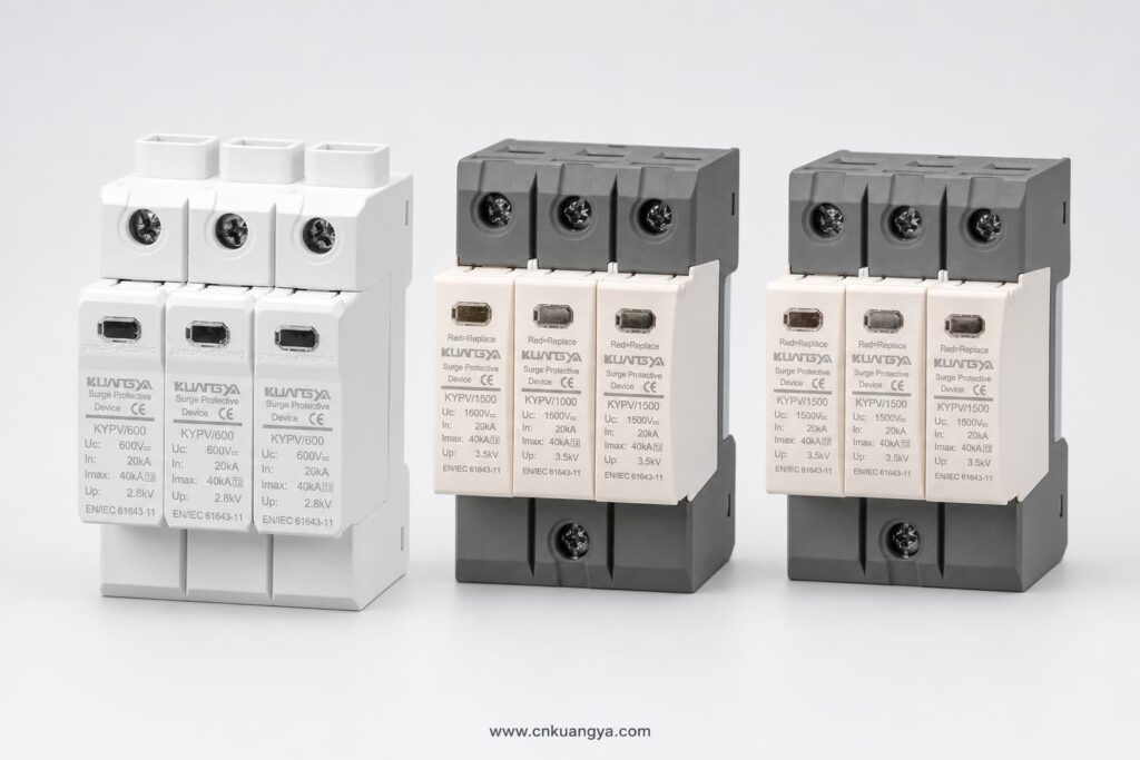
불충분한 Ucpv를 가진 SPD를 선택하면 조기 작동, 과열 또는 단선이 발생할 수 있습니다. 필요 이상으로 높은 전압 정격을 선택하면 전압 보호 레벨이 높아져 민감한 장비에 대한 보호 효과가 떨어질 수 있습니다.
PV SPD는 일반적으로 처리하도록 설계된 서지 전류에 따라 분류됩니다.
Type 2 SPD는 유도 낙뢰 서지 및 스위칭 과전압으로부터 보호하기 위해 일반적으로 사용됩니다.
일반적인 애플리케이션은 다음과 같습니다:
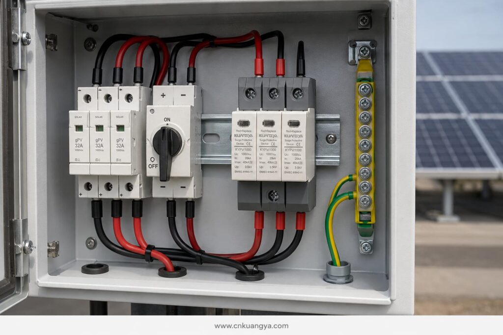
Type 2 장치는 일반적으로 공칭 방전 전류를 사용하여 사양이 지정되며 In 최대 방전 전류를 포함합니다. Imax, 이는 8/20 μs 전류 파형을 기준으로 합니다.
Type 1 SPD는 부분 낙뢰 전류를 방전하도록 설계되었습니다. 낙뢰 보호 설계상 낙뢰 전류가 전기 설비로 유입될 수 있다고 판단되는 경우에 필요할 수 있습니다.
Type 1 선정은 일반적으로 다음 사항과 관련이 있습니다:
1형(Type 1) 성능은 일반적으로 임펄스 방전 전류를 사용하여 표현됩니다. Iimp, 10/350 μs 파형을 기준으로 합니다.
1+2형(Type 1+2) 서지 보호 장치(SPD)는 낙뢰 전류 보호와 유도 서지 보호 기능을 하나의 장치에 결합한 것입니다.
다음의 경우 고려될 수 있습니다:
SPD 유형은 프로젝트의 피뢰 개념에 따라 선정되어야 합니다. 단순히 유형 번호가 높다고 해서 더 강력한 성능을 의미하는 것으로 간주하여 선택해서는 안 됩니다.
서로 다른 SPD 정격은 성능의 각기 다른 측면을 나타냅니다.
In 8/20 μs 파형을 사용하여 지정된 시험 조건 하에서 Type 2 SPD가 반복적으로 방전할 수 있는 전류를 나타냅니다.
Type 2 SPD를 비교할 때 사용되는 주요 정격 중 하나입니다.
Imax 지정된 시험 조건 하에서 SPD가 처리할 수 있는 최대 8/20 μs 방전 전류입니다.
높은 Imax 정격만으로는 특정 설치 환경에 SPD가 적합하다고 단정할 수 없습니다. In, Up, Ucpv, 단락 동작, 연결 방식 및 적용 가능한 시험 표준과 함께 고려해야 합니다.
Iimp Type 1 및 Type 1+2 장치에 사용되며, 10/350 μs 파형을 이용한 낙뢰 임펄스 전류 처리 능력을 나타냅니다.
Type 1 보호가 요구되는 경우, 프로젝트 사양에 따라 극당 또는 보호 모드당 Iimp 값을 비교하십시오.
Up indicates the residual voltage that appears across the SPD during the specified discharge test.
The Up value should be lower than the impulse withstand level of the equipment being protected. Connection cables also add voltage during a surge, so the effective protection level at the inverter can be higher than the SPD’s catalogue value.
This is why short, direct SPD connections are essential.
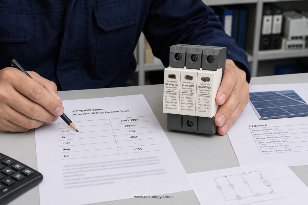
A PV DC circuit may be floating, functionally earthed, or configured according to a specific inverter topology. The SPD must use a connection arrangement suitable for that system.
Before selecting the number of poles or protection modes, confirm:
Do not assume that an AC SPD with a similar voltage can be used on the PV DC side. PV systems have specific continuous-voltage and fault-current characteristics. The device should be designed and tested for photovoltaic DC applications according to IEC/UNE-EN 61643-31.
A PV SPD must be able to disconnect safely if it reaches the end of its service life.
Important parameters include:
The external backup fuse should not be selected only according to the SPD’s physical size. Follow the SPD manufacturer’s data sheet and verify compatibility with the PV string current and the system’s fault characteristics.
The SPD protects against transient overvoltage. The gPV fuse or DC breaker protects against overcurrent and short-circuit conditions. One device cannot replace the other.
Typical DC SPD locations include:
The most suitable arrangement depends on cable length, exposure, lightning protection design, equipment withstand level, and project risk assessment.
For a compact rooftop installation with short DC cable routes, a Type 2 SPD near the inverter may provide the required protection when permitted by the design.
For longer routes between the PV array and inverter, coordinated SPDs may be required at both ends. This reduces the voltage stress that can develop along the cable and improves protection for equipment at each location.
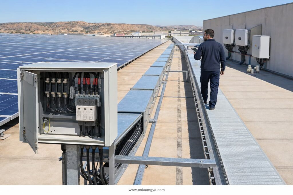
Some industry design guidance uses approximately 10 metres as a point at which additional coordination should be considered. This should not be treated as a universal rule for every Spanish installation. The final placement must follow the applicable design standard, risk assessment, cable routing, and equipment manufacturer’s instructions.
Even a correctly rated SPD can provide poor protection if it is installed with long or badly routed cables.
During a surge, cable inductance creates additional voltage. Longer conductors can therefore increase the total voltage reaching the inverter.
Good installation practice includes:
The objective is to reduce the total connection length and minimise the effective protection level at the protected equipment.
DIN-rail SPD modules do not automatically provide outdoor protection. Their environmental protection depends on the enclosure in which they are installed.
For rooftop and outdoor PV systems in Spain, check:
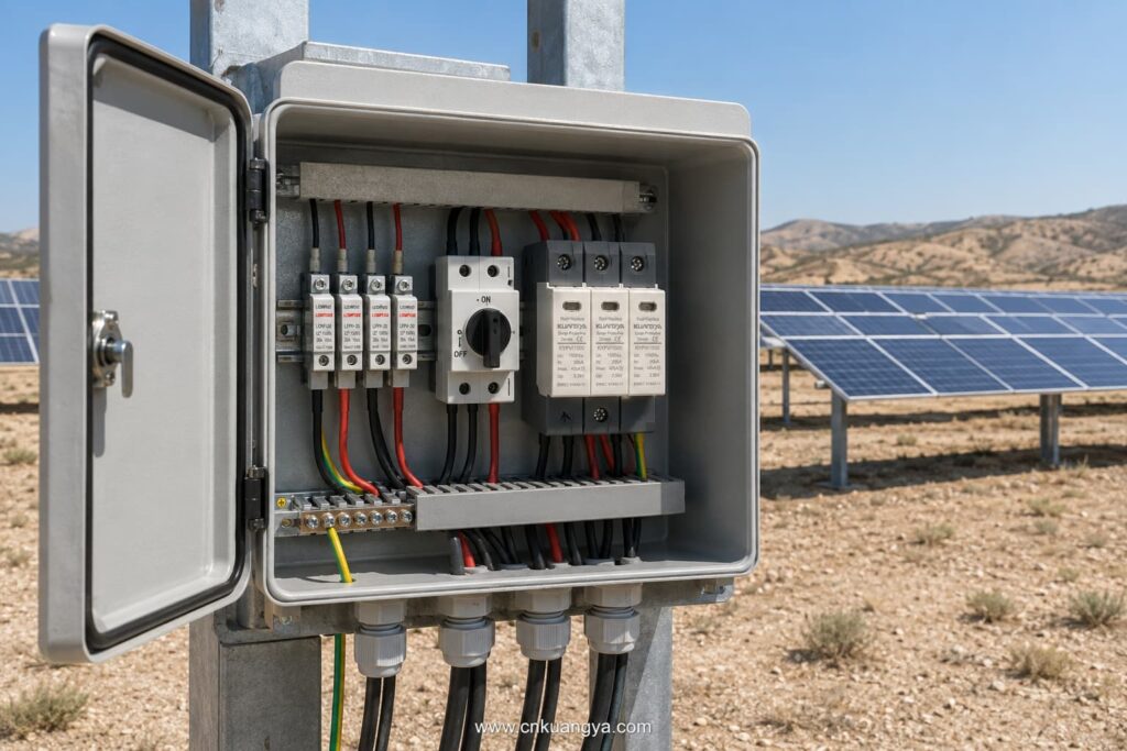
The SPD’s declared ratings apply under the operating conditions stated in its data sheet. High internal cabinet temperatures should be considered, especially in outdoor enclosures exposed to direct sunlight.
SPDs are not permanent, maintenance-free components. Their protective elements can deteriorate after repeated surge events.
Useful maintenance features include:
The module should be inspected according to the maintenance plan and after significant lightning activity or a known surge event.
Replace the module when:
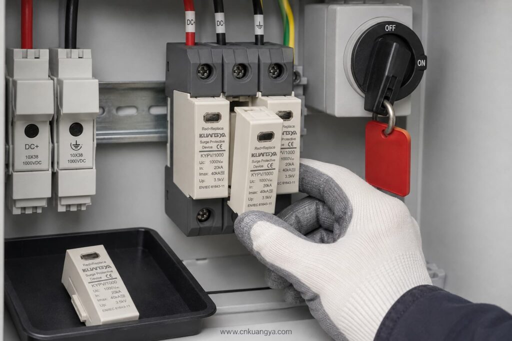
Always isolate the relevant DC circuit and follow safe working procedures before inspection or replacement.
| Project Condition | SPD Selection to Evaluate |
|---|---|
| Residential rooftop PV without expected lightning-current entry | Type 2 PV DC SPD |
| Commercial rooftop with long DC cable routes | Coordinated Type 2 SPDs at suitable locations |
| Building with an external lightning protection system | Type 1 or Type 1+2, depending on the lightning protection design |
| Utility-scale 1,500 V PV array | PV-specific 1,500 V SPD with suitable Type and discharge ratings |
| Combiner box exposed to induced surges | Type 2 PV DC SPD |
| Inverter requiring combined lightning and surge protection | Type 1+2 PV DC SPD if specified by the design |
This table is a preliminary guide only. It does not replace the project risk assessment or the work of an authorised electrical designer.
Providing complete technical information helps the supplier select the correct product and prevents delays.
Send the following details:
If the SPD type is not yet confirmed, provide the PV module data, number of modules per string, minimum design temperature, inverter model, system drawing, and lightning protection information.
Avoid these common errors:
Selecting a suitable 스페인 태양광 설비용 DC SPD requires coordination between the PV system voltage, lightning risk, SPD classification, installation location, earthing arrangement, and applicable Spanish requirements.
The most important steps are:
KUANGYA supplies DC SPDs for solar PV applications in 600 V, 1,000 V, and 1,500 V configurations, including Type 2 and Type 1+2 options.
View the KUANGYA DC SPD range for photovoltaic systems or contact us with your system voltage, SPD type, discharge-current requirements, wiring configuration, quantity, and project location to request a data sheet and B2B quotation.
Not automatically. Type 2 is widely used for induced lightning and switching surges, but the final selection depends on the lightning protection system, risk assessment, equipment location, and project requirements.
Only if the SPD’s Ucpv is suitable for the maximum calculated PV voltage under the lowest expected temperature. Do not rely only on the nominal system description.
In is the nominal discharge current used to evaluate repeated Type 2 surge performance. Imax is the maximum 8/20 μs discharge current the SPD can withstand under specified test conditions.
It is used where the design requires both partial lightning-current discharge and Type 2 surge-limiting performance at the same installation point.
Common locations include the combiner box and inverter DC input. Long cable routes or exposed systems may require coordinated SPDs at more than one location.
UNE-EN 61643-31 is the principal Spanish standard covering requirements and test methods for SPDs used in photovoltaic installations. The complete installation must also follow the REBT and other applicable technical requirements.
If your project has already reached the stage of deciding between Type 1, Type 2 and Type 1+2 protection, continue with our detailed guide to Type 1 vs Type 2 SPD for solar PV in Spain.
This article provides general technical guidance. Final SPD selection and installation should be verified by the responsible project designer or an authorised electrical professional in accordance with current Spanish requirements.

