WengYang Industriegebiet Yueqing Wenzhou 325000
Arbeitszeiten
Montag bis Freitag: 7AM - 7PM
Am Wochenende: 10AM - 5PM
WengYang Industriegebiet Yueqing Wenzhou 325000
Arbeitszeiten
Montag bis Freitag: 7AM - 7PM
Am Wochenende: 10AM - 5PM

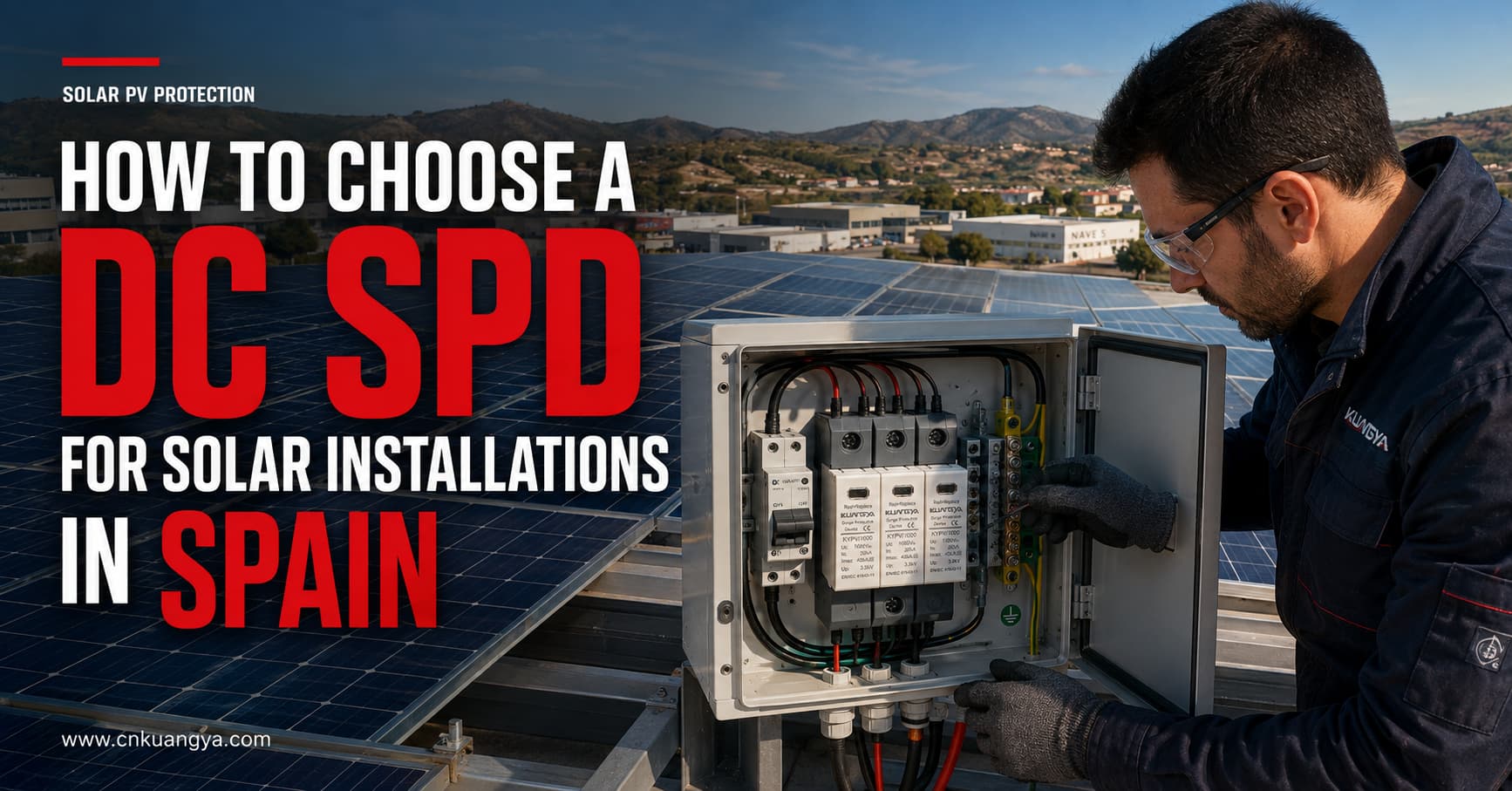
Photovoltaikanlagen sind transienten Überspannungen ausgesetzt, die durch Blitzeinschläge in der Nähe, Schaltvorgänge und Störungen in angeschlossenen Stromkreisen verursacht werden. Diese Ereignisse können Wechselrichter, Überwachungsgeräte, Anschlusskästen und andere empfindliche Komponenten beschädigen.
Die Auswahl des richtigen DC-Überspannungsschutzgeräts (SPD) für Solaranlagen in Spanien erfordert mehr als nur die Anpassung eines Geräts an die Nennspannung des Systems. Planer und Installateure müssen zudem die maximale Leerlaufspannung der PV-Anlage, die SPD-Klassifizierung, das Ableitvermögen, den Schutzpegel, die Erdungskonfiguration des Systems, die Leitungslänge, den Installationsort sowie die geltenden Normen berücksichtigen.
Die Auswahl eines DC-SPD umfasst jedoch mehr als nur die Anpassung eines Geräts an eine Nennspannung. Planer und Installateure müssen zudem die maximale Leerlaufspannung der PV-Anlage, die SPD-Klassifizierung, das Ableitvermögen, den Schutzpegel, die Erdungskonfiguration des Systems, die Leitungslänge, den Installationsort sowie die geltenden Normen berücksichtigen.
Dieser Leitfaden erläutert die Auswahl eines DC-SPD für Solaranlagen in Spanien und nennt die technischen Informationen, die vor einer Angebotsanfrage bestätigt werden sollten.
PV-Module und deren Anschlussleitungen werden üblicherweise über große, exponierte Flächen installiert. Lange DC-Leitungswege können als Pfade dienen, über die blitzinduzierte und schaltbedingte transiente Überspannungen den Wechselrichter erreichen.
Eine Überspannung muss nicht zwangsläufig von einem direkten Blitzeinschlag in die PV-Anlage herrühren. Blitzeinschläge in der Nähe können transiente Spannungen in DC-Leitungen induzieren, während Schaltvorgänge innerhalb der Installation ebenfalls elektrische Störungen verursachen können.
Ein DC-Überspannungsschutzgerät (SPD) ist dafür ausgelegt:
Ein Überspannungsschutzgerät (SPD) ersetzt weder eine Sicherung, einen Leitungsschutzschalter, einen Trennschalter, ein Erdungssystem noch ein äußeres Blitzschutzsystem. Jedes Gerät erfüllt eine unterschiedliche Schutzfunktion und muss als Teil des gesamten PV-Anlagendesigns koordiniert werden.
Niederspannungsinstallationen in Spanien unterliegen dem Reglamento Electrotécnico para Baja Tensión, allgemein bekannt als REBT. Das anzuwendende Design muss zudem die aktuellen technischen Anweisungen, Projektspezifikationen, lokalen Anforderungen sowie die in der Verordnung referenzierten Normen berücksichtigen.
Die offizielle Liste der mit dem REBT verbundenen Normen in Spanien umfasst:
Für internationale PV-Anwendungen sind zudem folgende IEC-Dokumente von Bedeutung:
IEC 61643-31 gilt für Überspannungsschutzgeräte, die an die Gleichstromseite von Photovoltaik-Anlagen mit Nennspannungen bis 1.500 V DC angeschlossen sind.
Die Projektanforderungen können je nach Installationsart, Risikobewertung, Standort, Wechselrichterdesign, externem Blitzschutzsystem sowie den Anforderungen der spanischen Behörden oder des autorisierten Installateurs variieren. Die Produktauswahl sollte daher vom Projektplaner oder einer qualifizierten Elektrofachkraft bestätigt werden.
Der erste Auswahlparameter ist die maximale Dauerspannung des SPD für das PV-System, die normalerweise wie folgt gekennzeichnet ist: Ucpv.
Wählen Sie ein SPD nicht allein auf Basis der Nennbetriebsspannung des Wechselrichters aus.
Die maximale Spannung eines PV-Strangs hängt ab von:
Die Spannung von PV-Modulen steigt bei sinkender Temperatur. Daher kann die maximale Leerlaufspannung des gesamten Strangs unter Kältebedingungen höher sein als unter Standardtestbedingungen.
Die Ucpv des SPD muss für die maximale Spannung geeignet sein, die dauerhaft am PV-Generator anliegen kann.
| PV-Anlage | Gängige SPD-Spannungsklasse | Wichtige Überprüfung |
|---|---|---|
| Kleine PV-Wohnanlage | 600 V DC | Überprüfung der maximalen Leerlaufspannung (Voc) des Strings im kalten Zustand |
| Photovoltaikanlagen für Wohn- oder Gewerbegebäude | 1.000 V DC | Wechselrichter- und String-Spannungsgrenzen prüfen |
| Kommerzielle oder großtechnische PV-Anlagen | 1.500 V DC | Verwenden Sie einen SPD, der speziell für 1.500-V-PV-Systeme ausgelegt ist |
Dies sind Anwendungsbeispiele, keine automatischen Auswahlregeln. Die endgültige SPD-Spannung muss auf der berechneten maximalen PV-Spannung und dem Anschlussplan des Herstellers basieren.
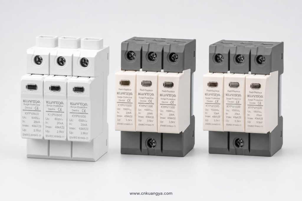
Die Auswahl eines SPD mit unzureichender Ucpv kann zu vorzeitigem Ansprechen, Überhitzung oder Trennung führen. Die Wahl einer unnötig hohen Spannungsbemessung kann zu einem höheren Spannungsschutzpegel und einem weniger wirksamen Schutz für empfindliche Geräte führen.
PV-Überspannungsschutzgeräte werden normalerweise nach dem Stoßstrom klassifiziert, für den sie ausgelegt sind.
Ein Typ 2 Überspannungsschutzgerät wird üblicherweise zum Schutz vor induzierten Blitzstoßströmen und Schaltüberspannungen verwendet.
Typische Anwendungen sind:
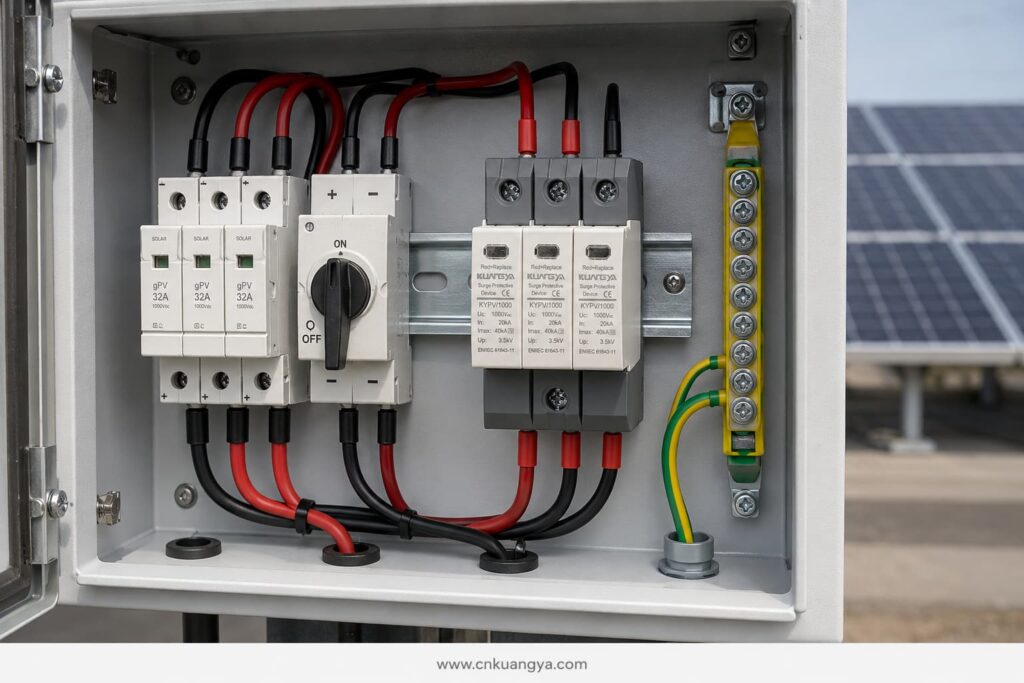
Typ-2-Geräte werden normalerweise unter Angabe des Nennableitstoßstroms spezifiziert Unter und des maximalen Ableitstoßstroms Imax, basierend auf einer 8/20 μs Stromstoßform.
Ein Typ-1-SPD ist für die Ableitung von Teilblitzströmen ausgelegt. Er kann erforderlich sein, wenn das Blitzschutzkonzept vorsieht, dass Blitzströme in die elektrische Anlage gelangen können.
Die Auswahl eines Typ-1-Geräts ist typischerweise verbunden mit:
Die Leistungsfähigkeit von Typ 1 wird normalerweise durch den Blitzstoßstrom ausgedrückt Iimp, basierend auf einer 10/350 μs Wellenform.
Ein Typ 1+2 Überspannungsschutzgerät kombiniert Blitzstrom- und induktiven Überspannungsschutz in einem Gerät.
Es kann in Betracht gezogen werden für:
Der SPD-Typ muss gemäß dem Blitzschutzkonzept des Projekts ausgewählt werden. Er sollte nicht nur deshalb gewählt werden, weil eine höhere Typennummer leistungsfähiger erscheint.
Unterschiedliche SPD-Nennwerte beschreiben verschiedene Leistungsaspekte.
Unter gibt den Strom an, den ein Typ-2-Überspannungsschutzgerät (SPD) unter den festgelegten Testbedingungen wiederholt ableiten kann, normalerweise unter Verwendung einer 8/20 μs-Wellenform.
Er ist einer der wichtigsten Bemessungswerte beim Vergleich von Typ-2-Überspannungsschutzgeräten.
Imax ist der maximale 8/20 μs-Ableitstrom, den das SPD unter seinen festgelegten Testbedingungen bewältigen kann.
Ein hoher Imax-Wert allein beweist nicht, dass ein SPD für eine bestimmte Installation geeignet ist. Er muss zusammen mit In, Up, Ucpv, dem Kurzschlussverhalten, der Anschlussart und der geltenden Prüfnorm betrachtet werden.
Iimp wird für Geräte des Typs 1 und Typs 1+2 verwendet und stellt die Blitzstromtragfähigkeit unter Verwendung einer 10/350 μs-Wellenform dar.
Wenn ein Schutz vom Typ 1 erforderlich ist, vergleichen Sie den Iimp-Wert pro Pol oder Schutzmodus gemäß der Projektspezifikation.
Nach oben gibt die Restspannung an, die während der spezifizierten Entladungsprüfung am SPD auftritt.
Der Up-Wert sollte niedriger sein als die Stoßspannungsfestigkeit der zu schützenden Geräte. Anschlusskabel erhöhen bei einem Überspannungsereignis ebenfalls die Spannung, sodass der effektive Schutzpegel am Wechselrichter höher sein kann als der Katalogwert des SPD.
Aus diesem Grund sind kurze, direkte SPD-Anschlüsse unerlässlich.
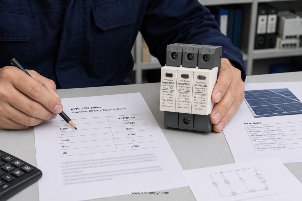
Ein PV-DC-Stromkreis kann erdfrei, funktionsgeerdet oder gemäß einer spezifischen Wechselrichtertopologie konfiguriert sein. Das SPD muss eine für dieses System geeignete Anschlussanordnung verwenden.
Bevor Sie die Anzahl der Pole oder Schutzmodi auswählen, bestätigen Sie:
Gehen Sie nicht davon aus, dass ein AC-SPD mit ähnlicher Spannung auf der PV-DC-Seite verwendet werden kann. PV-Systeme weisen spezifische Eigenschaften hinsichtlich Dauerspannung und Fehlerstrom auf. Das Gerät sollte für photovoltaische DC-Anwendungen gemäß IEC/UNE-EN 61643-31 ausgelegt und geprüft sein.
Ein PV-Überspannungsschutzgerät (SPD) muss in der Lage sein, sich bei Erreichen des Endes seiner Lebensdauer sicher zu trennen.
Wichtige Parameter sind:
Die externe Vorsicherung sollte nicht allein nach der physischen Größe des SPD ausgewählt werden. Befolgen Sie das Datenblatt des SPD-Herstellers und überprüfen Sie die Kompatibilität mit dem PV-String-Strom sowie den Fehlercharakteristiken des Systems.
Das SPD schützt vor transienten Überspannungen. Die gPV-Sicherung oder der DC-Leistungsschalter schützt vor Überstrom und Kurzschlussbedingungen. Ein Gerät kann das andere nicht ersetzen.
Typische Standorte für DC-SPDs sind:
Die am besten geeignete Anordnung hängt von der Leitungslänge, der Exposition, dem Blitzschutzkonzept, der Spannungsfestigkeit der Betriebsmittel und der Projektrisikobewertung ab.
Bei einer kompakten Dachanlage mit kurzen DC-Leitungswegen kann ein Typ-2-Überspannungsschutzgerät (SPD) in der Nähe des Wechselrichters den erforderlichen Schutz bieten, sofern dies durch die Auslegung zulässig ist.
Bei längeren Leitungsstrecken zwischen PV-Generator und Wechselrichter können koordinierte SPDs an beiden Enden erforderlich sein. Dies reduziert die Spannungsbelastung, die entlang des Kabels entstehen kann, und verbessert den Schutz der Geräte an beiden Standorten.
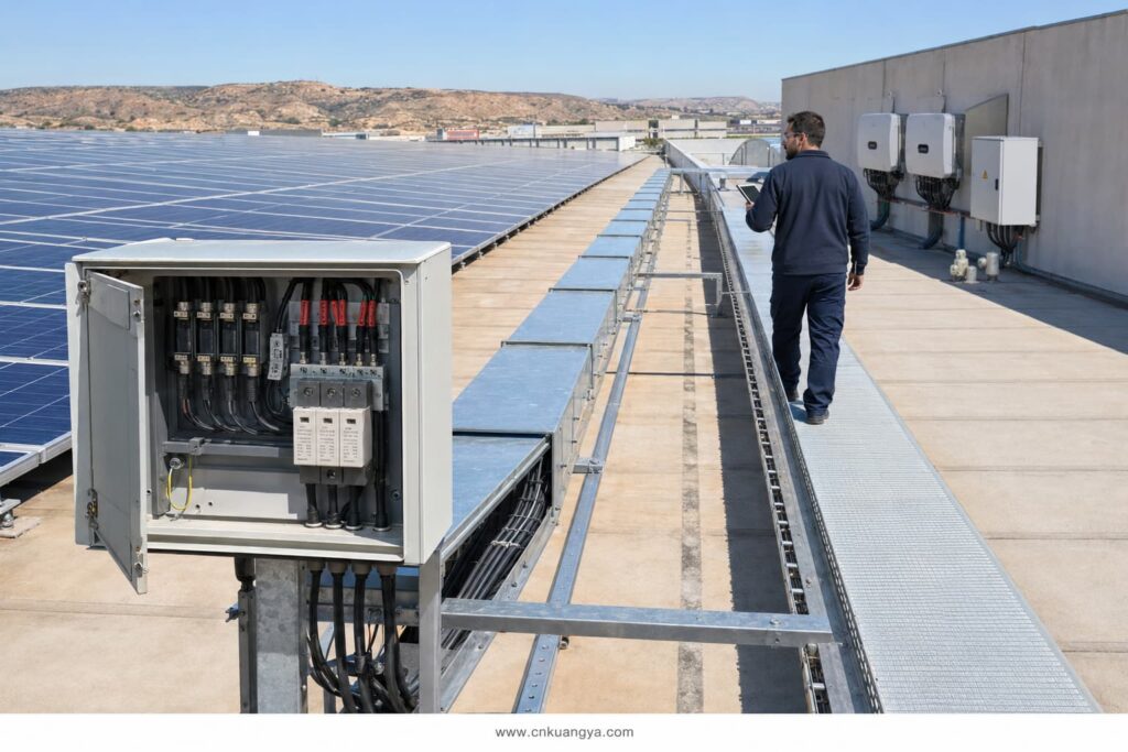
Einige Richtlinien der Industrie verwenden etwa 10 Meter als Richtwert, ab dem eine zusätzliche Koordination in Betracht gezogen werden sollte. Dies sollte nicht als allgemeingültige Regel für jede spanische Installation betrachtet werden. Die endgültige Platzierung muss den geltenden Auslegungsnormen, der Risikobewertung, der Leitungsführung und den Anweisungen des Geräteherstellers entsprechen.
Selbst ein korrekt dimensioniertes SPD kann einen unzureichenden Schutz bieten, wenn es mit langen oder schlecht verlegten Kabeln installiert wird.
Während eines Stoßstroms erzeugt die Leitungsinduktivität eine zusätzliche Spannung. Längere Leiter können daher die Gesamtspannung, die den Wechselrichter erreicht, erhöhen.
Gute Installationspraktiken umfassen:
Das Ziel ist es, die gesamte Leitungslänge zu reduzieren und den effektiven Schutzpegel am geschützten Gerät zu minimieren.
DIN-rail SPD modules do not automatically provide outdoor protection. Their environmental protection depends on the enclosure in which they are installed.
For rooftop and outdoor PV systems in Spain, check:
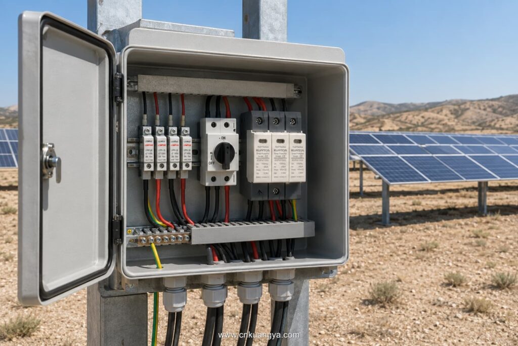
The SPD’s declared ratings apply under the operating conditions stated in its data sheet. High internal cabinet temperatures should be considered, especially in outdoor enclosures exposed to direct sunlight.
SPDs are not permanent, maintenance-free components. Their protective elements can deteriorate after repeated surge events.
Useful maintenance features include:
The module should be inspected according to the maintenance plan and after significant lightning activity or a known surge event.
Replace the module when:
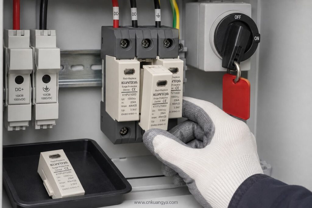
Always isolate the relevant DC circuit and follow safe working procedures before inspection or replacement.
| Project Condition | SPD Selection to Evaluate |
|---|---|
| Residential rooftop PV without expected lightning-current entry | Type 2 PV DC SPD |
| Commercial rooftop with long DC cable routes | Coordinated Type 2 SPDs at suitable locations |
| Building with an external lightning protection system | Type 1 or Type 1+2, depending on the lightning protection design |
| Utility-scale 1,500 V PV array | PV-specific 1,500 V SPD with suitable Type and discharge ratings |
| Combiner box exposed to induced surges | Type 2 PV DC SPD |
| Inverter requiring combined lightning and surge protection | Type 1+2 PV DC SPD if specified by the design |
This table is a preliminary guide only. It does not replace the project risk assessment or the work of an authorised electrical designer.
Providing complete technical information helps the supplier select the correct product and prevents delays.
Send the following details:
If the SPD type is not yet confirmed, provide the PV module data, number of modules per string, minimum design temperature, inverter model, system drawing, and lightning protection information.
Avoid these common errors:
Selecting a suitable DC-Überspannungsschutzgeräts (SPD) für Solaranlagen in Spanien requires coordination between the PV system voltage, lightning risk, SPD classification, installation location, earthing arrangement, and applicable Spanish requirements.
The most important steps are:
KUANGYA supplies DC SPDs for solar PV applications in 600 V, 1,000 V, and 1,500 V configurations, including Type 2 and Type 1+2 options.
View the KUANGYA DC SPD range for photovoltaic systems or contact us with your system voltage, SPD type, discharge-current requirements, wiring configuration, quantity, and project location to request a data sheet and B2B quotation.
Not automatically. Type 2 is widely used for induced lightning and switching surges, but the final selection depends on the lightning protection system, risk assessment, equipment location, and project requirements.
Only if the SPD’s Ucpv is suitable for the maximum calculated PV voltage under the lowest expected temperature. Do not rely only on the nominal system description.
In is the nominal discharge current used to evaluate repeated Type 2 surge performance. Imax is the maximum 8/20 μs discharge current the SPD can withstand under specified test conditions.
It is used where the design requires both partial lightning-current discharge and Type 2 surge-limiting performance at the same installation point.
Common locations include the combiner box and inverter DC input. Long cable routes or exposed systems may require coordinated SPDs at more than one location.
UNE-EN 61643-31 is the principal Spanish standard covering requirements and test methods for SPDs used in photovoltaic installations. The complete installation must also follow the REBT and other applicable technical requirements.
If your project has already reached the stage of deciding between Type 1, Type 2 and Type 1+2 protection, continue with our detailed guide to Type 1 vs Type 2 SPD for solar PV in Spain.
This article provides general technical guidance. Final SPD selection and installation should be verified by the responsible project designer or an authorised electrical professional in accordance with current Spanish requirements.

