منطقة ونغ يانغ الصناعية يويتشينغ ونتشو 325000
ساعات العمل
من الاثنين إلى الجمعة: 7 صباحاً - 7 مساءً
عطلة نهاية الأسبوع 10 صباحاً - 5 مساءً
منطقة ونغ يانغ الصناعية يويتشينغ ونتشو 325000
ساعات العمل
من الاثنين إلى الجمعة: 7 صباحاً - 7 مساءً
عطلة نهاية الأسبوع 10 صباحاً - 5 مساءً

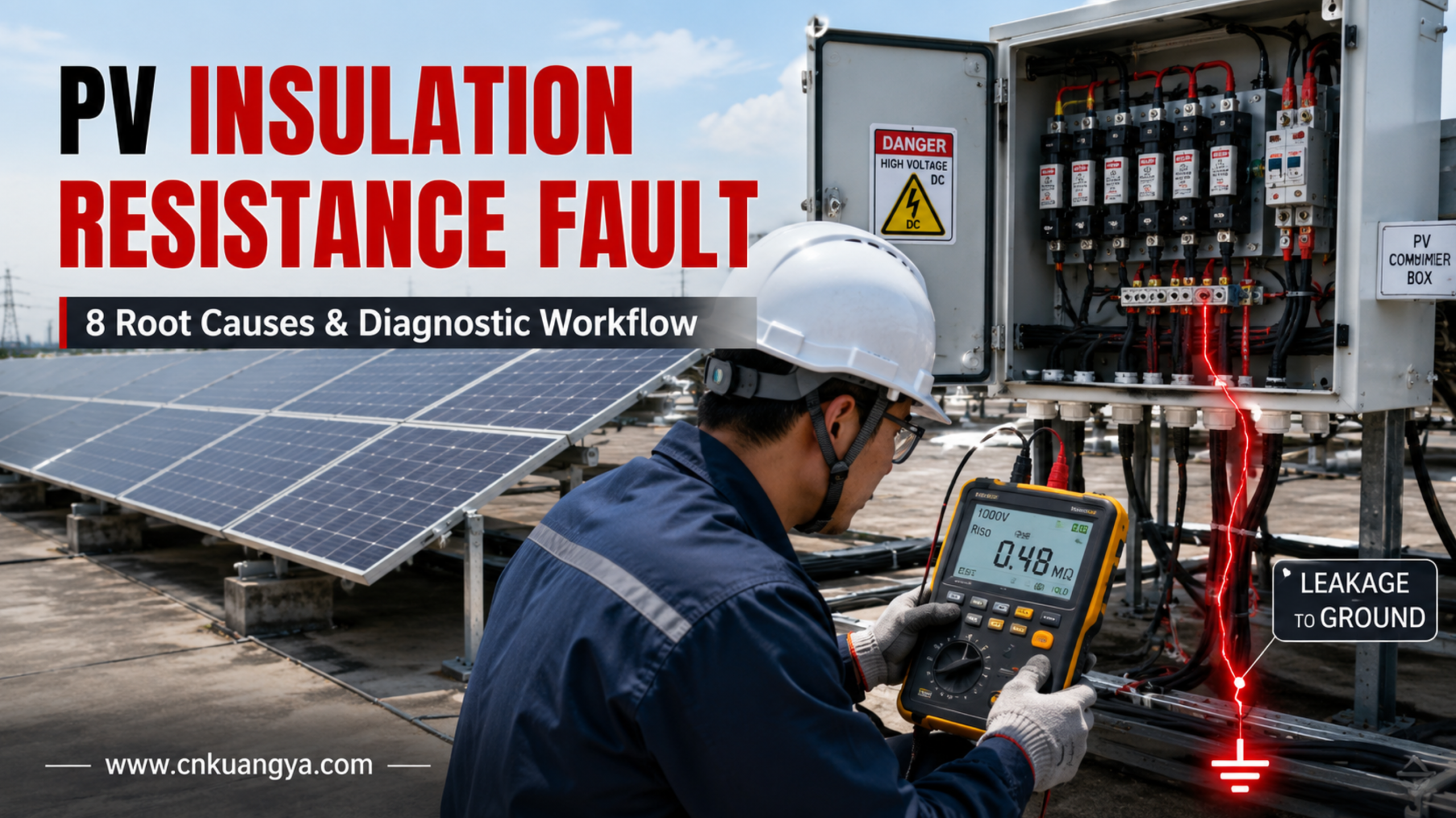
A عطل مقاومة العزل في الأنظمة الكهروضوئية يعد أحد أكثر المشكلات إحباطاً في عمليات تشغيل وصيانة الأنظمة الشمسية.
قد يرفض العاكس (Inverter) البدء في العمل في الصباح. وقد يختفي التحذير بعد عدة ساعات من الجفاف ويعود للظهور بعد هطول الأمطار. قد تبدو سلسلة واحدة طبيعية كهربائياً عند قياس جهد الدائرة المفتوحة، ومع ذلك تظل مصفوفة الألواح الكهروضوئية بأكملها تبلغ عن حالة انخفاض في مقاومة العزل.
هذه الأعطال صعبة لأن المشكلة لا تكون دائماً عبارة عن دائرة قصر (Short Circuit) مباشرة.
يمكن للمصفوفة الشمسية الاستمرار في إنتاج جهد طبيعي ظاهرياً بينما تؤدي الرطوبة، أو تلف العزل، أو الموصلات الملوثة، أو تدهور مكونات الألواح، أو وجود جهاز تيار مستمر معيب إلى إنشاء مسار موصل غير مرغوب فيه بين دائرة التيار المستمر الحية والأرضي.
قد تكون النتيجة:
يشرح هذا الدليل كيفية تطور أعطال العزل في الأنظمة الكهروضوئية، ولماذا تظهر غالباً بشكل متقطع، وكيف يمكن للفنيين استخدام عملية تشخيص منظمة بدلاً من استبدال المكونات بشكل عشوائي.
يجب أن يراعي تصميم مصفوفة الخلايا الكهروضوئية متطلبات التوصيلات الكهربائية للتيار المستمر، والحماية الكهربائية، والتأريض، ومراقبة العزل، والكشف عن أعطال الأرضي. يتم تناول مبادئ السلامة هذه في معيار IEC 62548-1 الخاص بتصميم مصفوفة الخلايا الكهروضوئية. يغطي إطار عمل IEC 62548-1 الحالي التوصيلات الكهربائية للتيار المستمر لمصفوفة الخلايا الكهروضوئية، والحماية الكهربائية، وأحكام التبديل والتأريض، بينما يتناول معيار IEC 62446-1 التوثيق واختبارات التشغيل والتفتيش، ويتناول معيار IEC 62446-2 الصيانة واستكشاف الأخطاء وإصلاحها لأنظمة الخلايا الكهروضوئية المتصلة بالشبكة.
تشمل الأسباب الأكثر شيوعًا ما يلي:
أهم قاعدة لاستكشاف الأخطاء وإصلاحها هي:
لا تتعامل مع خطأ العزل في النظام الكهروضوئي على أنه مشكلة في العاكس (Inverter) حتى يتم عزل مصفوفة التيار المستمر واختبارها بشكل منهجي.
قد يكتشف العاكس ببساطة مشكلة موجودة في مكان ما في الجزء العلوي من الحقل الكهروضوئي.
في المصفوفة الكهروضوئية السليمة، يجب أن تظل موصلات التيار المستمر الموجبة والسالبة معزولة بشكل كافٍ عن الأجزاء الموصلة التي يمكن الوصول إليها والأرضي وفقاً لتصميم النظام.
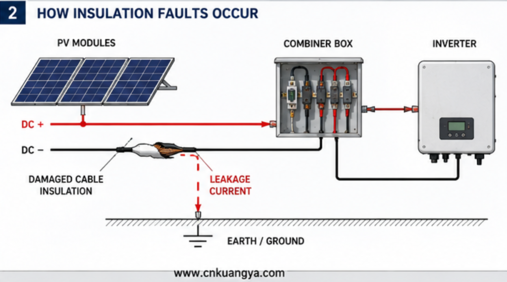
تنشأ مشكلة في العزل عند تكون مسار موصل غير مقصود بين دائرة التيار المستمر الحية ومسار موصل آخر أو مرجع أرضي.
قد ينشأ هذا المسار بسبب:
لا يبدأ العطل بالضرورة كدائرة قصر معدنية كاملة.
قد يبدأ كمسار تسريب ضعيف نسبياً.
ولهذا السبب يمكن لنظام الطاقة الكهروضوئية أحياناً:
هذا السلوك المتقطع هو أحد الأسباب التي تجعل أعطال العزل تستهلك الكثير من ساعات الصيانة.
Modern power conversion equipment may monitor the electrical relationship between the PV DC circuit and earth before or during operation.
When the detected insulation condition falls outside the inverter manufacturer’s permitted range, the inverter may:
The exact alarm name varies by manufacturer.
Examples of descriptions commonly encountered in the field include:
The important point is that the alarm identifies a condition, not necessarily the failed component.
Replacing the inverter without testing the array may therefore fail to solve the problem.
PV installation standards distinguish between the design of the array, the installation of PV equipment, and testing and maintenance activities. A proper diagnosis should therefore examine the complete DC system rather than only the power conversion equipment.
An insulation alarm should therefore be investigated as part of the wider DC protection architecture rather than treated as an isolated inverter problem. For a broader review of surge, overcurrent, arc-fault, grounding, and insulation risks around the inverter, see our guide to Solar Inverter Protection.
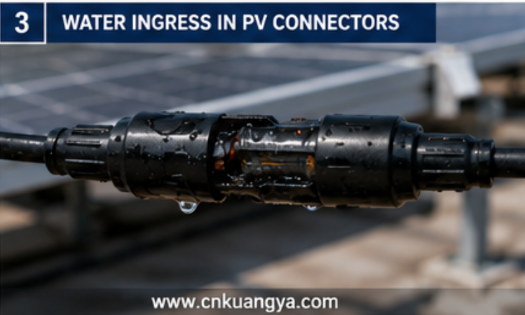
Water ingress is one of the first conditions technicians should investigate when an insulation alarm is strongly related to weather.
A connector may appear mechanically connected while still allowing moisture to reach conductive surfaces.
Possible reasons include:
The fault may be difficult to reproduce.
During dry weather, the leakage path may become weak enough for the inverter to start.
After rain or condensation, conductivity increases and the alarm returns.
A system:
This pattern should immediately direct attention toward moisture-sensitive components.
However, technicians should not assume that the first wet connector they find is the only problem.
Large arrays may contain multiple degraded points.
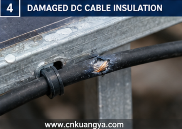
PV cables are exposed to long-term environmental and mechanical stress.
Possible damage mechanisms include:
A cable does not need to be completely severed to create an insulation problem.
A small damaged area may expose insulation to:
The resulting leakage path can be intermittent.
Technicians often inspect only visible cable sections.
But cable damage frequently occurs at:
A good inspection therefore follows the actual cable route rather than only the easy-to-see portions.
Not every insulation fault originates in the field wiring.
The PV module itself can become part of the leakage path.
Potential areas include:
Environmental exposure can gradually affect electrical insulation.
The diagnostic challenge is that module output voltage may still appear normal.
A technician may measure acceptable open-circuit voltage and conclude that the module is healthy.
However:
Normal voltage does not prove that insulation to earth is healthy.
These are different electrical conditions.
Module safety requirements are intended to address risks including breakdown of internal or external components that could contribute to electric shock or fire hazards.
Connector problems are frequently discussed only as overheating or arc-fault risks.
However, poor connector installation can also contribute to insulation problems.
Possible issues include:
A connector problem may evolve over time.
The sequence can be:
Mechanical weakness → moisture entry → corrosion or contamination → reduced insulation performance
In another case:
Poor electrical contact → heating → material degradation → carbonized conductive path
This shows why insulation resistance, thermal problems and arc-fault risks should not always be treated as completely separate failure categories.
One defect can develop through several stages.
A surge protective device is installed to manage transient overvoltage.
However, an SPD is also connected electrically between the protected conductors and the relevant protection path.
After repeated electrical stress or internal deterioration, a damaged device may become part of a leakage problem.
Therefore, when troubleshooting an unexplained insulation fault inside a:
the SPD should be included in the diagnostic process.
Do not simply remove an SPD permanently because the insulation alarm disappears.
That only identifies a possible fault source.
The correct action is to:
A failed protection device should not be solved by leaving the system unprotected.
IEC 62548-1 includes the design of DC array wiring and electrical protection devices within PV arrays.
The DC isolator is another component that should not be ignored.
Inside a DC switching device, insulation performance can be affected by:
An isolator may still appear to switch mechanically while its internal electrical condition has deteriorated.Moisture ingress, contaminated insulating surfaces, heat damage, and deteriorated internal contacts can also create broader reliability problems. Our detailed guide to DC Isolator Switch Failure explains how these defects develop and how they should be inspected.
Visible warning signs may include:
However, not every insulation defect is externally visible.
A systematic diagnostic process may require isolating sections of the circuit to determine whether the fault remains upstream or downstream of a particular device.
Many PV insulation faults are created during installation but appear months or years later.Incorrect cable routing, poor terminal preparation, reversed polarity, unsuitable protection devices, and installation errors can also create hidden DC-side defects. See 10 Common DC Protection Wiring Mistakes for a broader review of installation practices that can reduce long-term system reliability.
Consider a cable that is:
On the installation day, the insulation may remain intact.
Later, repeated:
can turn a minor installation defect into an electrical fault.
Projects in different environments may experience different dominant risks.
Possible concerns include:
Possible concerns include:
Possible concerns include:
The same alarm code can therefore have very different physical causes depending on the project environment.
Sometimes technicians search for one dramatically failed component.
But a large array may have no single obvious fault.
Instead, many small leakage paths can combine.
A large installation contains:
Each individual component may contribute only a small leakage path.
Together, however, the total insulation condition seen by the monitoring system can become problematic.
This is especially important when troubleshooting:
The diagnostic method must therefore be capable of dividing the system into smaller sections.
Without sectional isolation, technicians may spend hours looking for one visibly damaged component that does not exist.
This is one of the most useful diagnostic clues.
A solar plant may report:
Low insulation resistance at 6:30 a.m.
Then:
Normal operation at 10:00 a.m.
لماذا؟
One possible explanation is environmental moisture.
Overnight:
After sunrise:
The system appears to “repair itself.”
It has not.
The underlying defect may still exist.
This is why maintenance teams should record:
Fault timing can provide important information before the first electrical test is performed.
These terms are often used incorrectly.
An unwanted conductive path reduces the electrical isolation between the live circuit and earth or other conductive parts.
It may be relatively weak or intermittent.
A live conductor develops an unintended connection toward ground or grounded conductive material.
The severity depends on the electrical system and fault path.
A low-impedance connection occurs between points that should remain at different electrical potentials.
This can produce much higher current.
Current crosses an unintended gap through an electrical arc.
An arc fault may be:
A system can also experience more than one fault mechanism simultaneously.
على سبيل المثال:
Damaged insulation → leakage → carbonization → arc formation
Therefore, accurate diagnosis is more useful than simply assigning one general label such as “electrical fault.”
Random component replacement is one of the least efficient ways to troubleshoot a large PV system.
A better method is progressive isolation.
Before resetting the system, record:
This information may later reveal a pattern.
PV arrays can remain energized when exposed to sufficient light.
Technicians should follow the required site procedures, equipment instructions and applicable electrical safety practices before disconnecting, testing or opening equipment.
IEC 62446-1 addresses commissioning tests and inspection, while IEC 62446-2 provides maintenance-related requirements and recommendations for grid-connected PV systems, including corrective maintenance and troubleshooting.
The key question is:
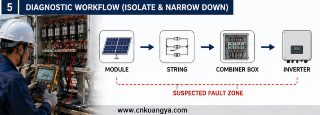
Is the fault in the inverter, main DC circuit, combiner box, string wiring or module section?
Large systems should be progressively divided into smaller electrical sections.
The objective is to determine:
Fault remains → problem is still inside the connected section
أو
Fault disappears → investigate the isolated section
This is more efficient than testing every module immediately.
When multiple strings are available, compare the suspected string with healthy strings.
Useful comparisons may include:
The objective is to identify the abnormal branch.
Prioritize locations such as:
Visual inspection should support electrical testing rather than replace it.
Once a problematic string is identified, divide the string or circuit into smaller sections where the system design and safe procedures allow.
This transforms:
“The entire PV plant has an insulation fault.”
into:
“The problem is located within this specific section.”
That is the central principle of efficient fault localization.
After identifying the fault source:
Then verify that the system has returned to an acceptable condition before normal operation.
An intermittent fault creates a dangerous temptation.
The technician resets the inverter.
The system starts.
The service ticket is closed.
Then the alarm returns after the next rain.
Restarting may temporarily restore generation, but it does not answer:
Repeated resets can turn a diagnosable early-stage problem into a more expensive failure.
Avoid:
Connectors should not carry unnecessary cable weight or remain in positions where water and contamination can accumulate.
Combiner boxes and other outdoor enclosures require:
Heavy rain and extreme environmental conditions can reveal developing insulation weaknesses.
Do not wait until an inverter refuses to start.
Periodic inspection and testing can help identify deterioration before it becomes a prolonged production problem.
IEC 62446-2 specifically addresses preventive, corrective and performance-related maintenance of grid-connected PV systems, including maintenance for reliability, safety, fire prevention and troubleshooting.
Experienced troubleshooting teams do not look only at the alarm.
They look at the pattern.
| Fault Pattern | Possible Direction |
|---|---|
| Only after rain | Moisture or ingress |
| Mainly early morning | Condensation-sensitive leakage |
| One specific string | Local string or module fault |
| Entire array | Common DC equipment or distributed leakage |
| After maintenance | Installation or reconnection issue |
| After electrical storm | Inspect affected protective equipment and connected circuits |
| Gradually increasing frequency | Progressive deterioration |
This table is not a substitute for testing.
Its purpose is to help determine where investigation should begin.
It generally means that the electrical isolation between the live PV DC circuit and earth or other conductive parts is lower than the equipment or system expects.
The cause must be identified through inspection and testing.
Moisture may create or strengthen an unintended leakage path in:
The fact that the fault disappears after drying does not mean the system is permanently repaired.
نعم.
Possible sources can include the module junction box, external leads or deterioration of the module insulation system.
Normal open-circuit voltage alone does not prove healthy insulation.
A damaged or degraded device connected to the DC protection circuit may need to be considered during diagnosis.
The device should be tested or replaced appropriately rather than permanently removed from the protection system.
Potentially.
Moisture, contamination, heat damage or internal electrical degradation may affect the condition of the device.
Temperature and moisture conditions may change.
Morning condensation or humidity can strengthen a leakage path that becomes less conductive as equipment dries and warms.
Not automatically.
The inverter may simply be detecting an upstream PV array problem.
The DC field should be systematically investigated before the inverter is assumed to be defective.
لا يوجد.
They are different electrical fault mechanisms, although deterioration can sometimes allow one fault condition to develop into another.
A عطل مقاومة العزل في الأنظمة الكهروضوئية should not be treated as a mysterious inverter error.
It is an electrical condition that requires structured fault localization.
تشمل الأسباب الأكثر شيوعًا ما يلي:
The most effective diagnostic strategy is not random replacement.
بل هو:
Record → Isolate → Divide → Compare → Inspect → Test → Repair → Verify
This method turns a plant-wide alarm into a manageable electrical problem.
As photovoltaic systems become larger and DC architectures become more complex, insulation integrity remains a fundamental part of safe and reliable PV operation. Current IEC frameworks separately address PV array design, electrical installation, testing, inspection and maintenance, reinforcing the need to treat insulation performance as a system-level engineering issue rather than simply an inverter alarm.

