WengYang Industrial Zone Yueqing Wenzhou 325000
Horas de trabalho
De segunda a sexta-feira: das 7h às 19h
Fim de semana: 10:00 - 17:00
WengYang Industrial Zone Yueqing Wenzhou 325000
Horas de trabalho
De segunda a sexta-feira: das 7h às 19h
Fim de semana: 10:00 - 17:00

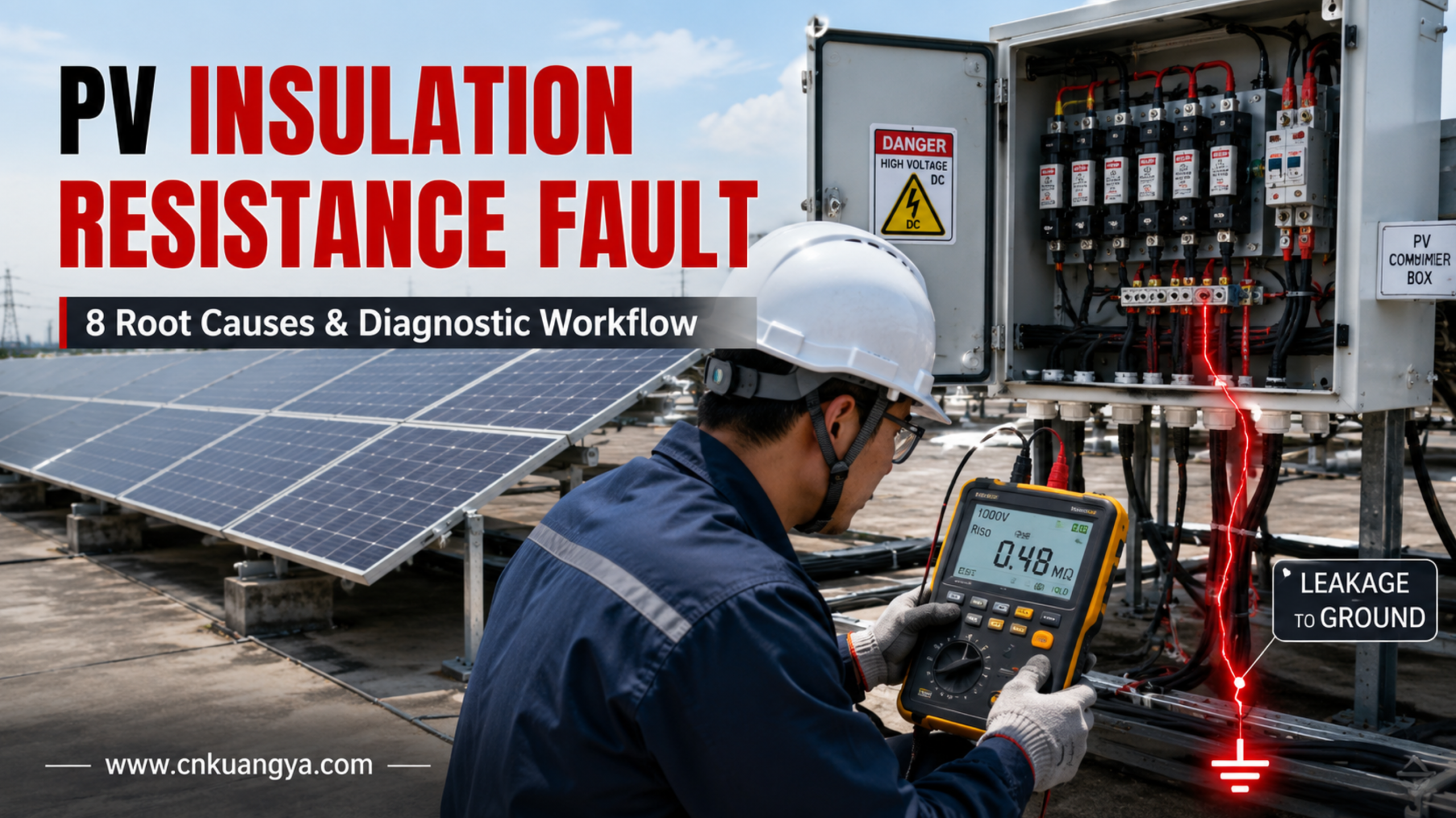
A Falha de resistência de isolamento fotovoltaico é um dos problemas mais frustrantes na operação e manutenção de sistemas solares.
O inversor pode recusar-se a iniciar pela manhã. Um aviso pode desaparecer após várias horas de tempo seco e retornar após a chuva. Uma string pode parecer eletricamente normal quando a tensão de circuito aberto é medida, mas todo o arranjo fotovoltaico ainda reporta uma condição de baixa resistência de isolamento.
Estas falhas são complexas porque o problema nem sempre é um curto-circuito direto.
Um arranjo solar pode continuar a produzir uma tensão aparentemente normal enquanto a umidade, isolamento danificado, conectores contaminados, componentes de módulos deteriorados ou um dispositivo CC defeituoso criam um caminho condutor indesejado entre o circuito CC energizado e a terra.
O resultado pode ser:
Este guia explica como as falhas de isolamento fotovoltaico se desenvolvem, por que aparecem frequentemente de forma intermitente e como os técnicos podem utilizar um processo de diagnóstico estruturado em vez de substituir componentes aleatoriamente.
O projeto de arranjos fotovoltaicos deve considerar os requisitos de cabeamento CC, proteção elétrica, aterramento, monitoramento de isolamento e detecção de falhas à terra. Estes princípios de segurança são abordados na IEC 62548-1 para projeto de arranjos fotovoltaicos. A estrutura atual da IEC 62548-1 abrange o cabeamento CC, proteção elétrica, dispositivos de seccionamento e aterramento de arranjos fotovoltaicos, enquanto a IEC 62446-1 aborda documentação, testes de comissionamento e inspeção, e a IEC 62446-2 aborda a manutenção e resolução de problemas em sistemas fotovoltaicos conectados à rede.
As causas mais comuns incluem:
A regra de resolução de problemas mais importante é:
Não trate uma falha de isolamento fotovoltaico como um problema do inversor até que o arranjo CC tenha sido sistematicamente isolado e testado.
O inversor pode estar simplesmente a detetar um problema localizado algures a montante no campo fotovoltaico.
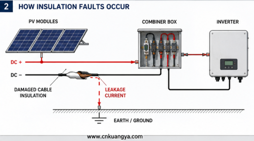
Num arranjo fotovoltaico em bom estado, os condutores CC positivo e negativo devem permanecer adequadamente isolados das partes condutoras acessíveis e da terra, de acordo com o projeto do sistema.
Um problema de isolamento ocorre quando um caminho condutor não intencional se forma entre o circuito CC energizado e outro caminho condutor ou referência de terra.
O caminho pode ser criado por:
A falha não começa necessariamente como um curto-circuito metálico completo.
Pode começar como um caminho de fuga relativamente fraco.
É por isso que um sistema fotovoltaico pode, por vezes:
Este comportamento intermitente é uma das razões pelas quais as falhas de isolamento podem consumir muitas horas de manutenção.
Equipamentos modernos de conversão de energia podem monitorar a relação elétrica entre o circuito CC fotovoltaico e a terra antes ou durante a operação.
Quando a condição de isolamento detectada estiver fora da faixa permitida pelo fabricante do inversor, o inversor pode:
O nome exato do alarme varia de acordo com o fabricante.
Exemplos de descrições comumente encontradas em campo incluem:
O ponto importante é que o alarme identifica uma condição, não necessariamente o componente com falha.
Substituir o inversor sem testar o arranjo pode, portanto, não resolver o problema.
As normas de instalação fotovoltaica distinguem entre o projeto do arranjo, a instalação de equipamentos fotovoltaicos e as atividades de teste e manutenção. Um diagnóstico adequado deve, portanto, examinar todo o sistema CC em vez de apenas o equipamento de conversão de energia.
Um alarme de isolamento deve, portanto, ser investigado como parte da arquitetura de proteção CC mais ampla, em vez de ser tratado como um problema isolado do inversor. Para uma análise mais abrangente sobre riscos de surtos, sobrecorrente, arco elétrico, aterramento e isolamento em torno do inversor, consulte nosso guia para Proteção do inversor solar.
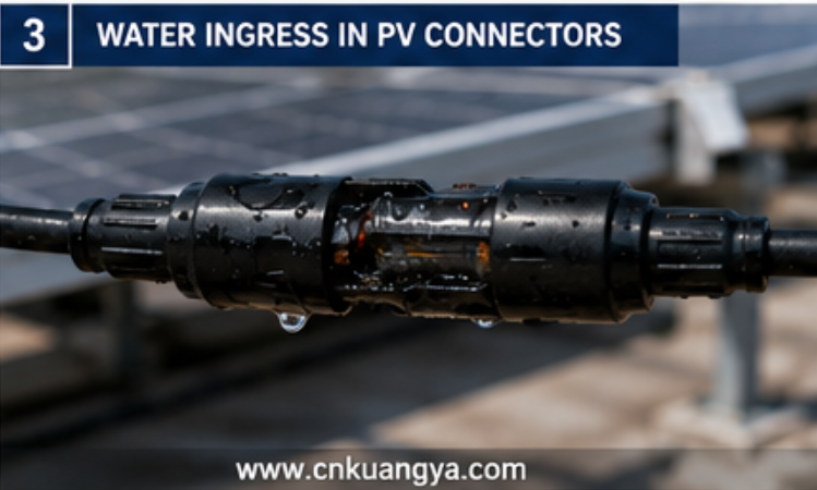
A entrada de água é uma das primeiras condições que os técnicos devem investigar quando um alarme de isolamento está fortemente relacionado às condições climáticas.
Um conector pode parecer mecanicamente conectado, mas ainda permitir que a umidade alcance superfícies condutoras.
As possíveis razões incluem:
A falha pode ser difícil de reproduzir.
Durante o tempo seco, o caminho de fuga pode tornar-se fraco o suficiente para que o inversor inicie.
Após chuva ou condensação, a condutividade aumenta e o alarme retorna.
Um sistema:
Este padrão deve direcionar imediatamente a atenção para componentes sensíveis à umidade.
No entanto, os técnicos não devem assumir que o primeiro conector úmido encontrado é o único problema.
Grandes arranjos podem conter múltiplos pontos degradados.
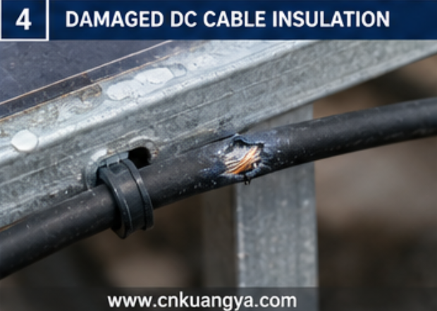
Os cabos fotovoltaicos estão expostos a estresse ambiental e mecânico de longo prazo.
Possíveis mecanismos de dano incluem:
A cable does not need to be completely severed to create an insulation problem.
A small damaged area may expose insulation to:
The resulting leakage path can be intermittent.
Technicians often inspect only visible cable sections.
But cable damage frequently occurs at:
A good inspection therefore follows the actual cable route rather than only the easy-to-see portions.
Not every insulation fault originates in the field wiring.
The PV module itself can become part of the leakage path.
Potential areas include:
Environmental exposure can gradually affect electrical insulation.
The diagnostic challenge is that module output voltage may still appear normal.
A technician may measure acceptable open-circuit voltage and conclude that the module is healthy.
However:
Normal voltage does not prove that insulation to earth is healthy.
These are different electrical conditions.
Module safety requirements are intended to address risks including breakdown of internal or external components that could contribute to electric shock or fire hazards.
Connector problems are frequently discussed only as overheating or arc-fault risks.
However, poor connector installation can also contribute to insulation problems.
Possible issues include:
A connector problem may evolve over time.
The sequence can be:
Mechanical weakness → moisture entry → corrosion or contamination → reduced insulation performance
In another case:
Poor electrical contact → heating → material degradation → carbonized conductive path
This shows why insulation resistance, thermal problems and arc-fault risks should not always be treated as completely separate failure categories.
One defect can develop through several stages.
A surge protective device is installed to manage transient overvoltage.
However, an SPD is also connected electrically between the protected conductors and the relevant protection path.
After repeated electrical stress or internal deterioration, a damaged device may become part of a leakage problem.
Therefore, when troubleshooting an unexplained insulation fault inside a:
the SPD should be included in the diagnostic process.
Do not simply remove an SPD permanently because the insulation alarm disappears.
That only identifies a possible fault source.
The correct action is to:
A failed protection device should not be solved by leaving the system unprotected.
IEC 62548-1 includes the design of DC array wiring and electrical protection devices within PV arrays.
The DC isolator is another component that should not be ignored.
Inside a DC switching device, insulation performance can be affected by:
An isolator may still appear to switch mechanically while its internal electrical condition has deteriorated.Moisture ingress, contaminated insulating surfaces, heat damage, and deteriorated internal contacts can also create broader reliability problems. Our detailed guide to DC Isolator Switch Failure explains how these defects develop and how they should be inspected.
Visible warning signs may include:
However, not every insulation defect is externally visible.
A systematic diagnostic process may require isolating sections of the circuit to determine whether the fault remains upstream or downstream of a particular device.
Many PV insulation faults are created during installation but appear months or years later.Incorrect cable routing, poor terminal preparation, reversed polarity, unsuitable protection devices, and installation errors can also create hidden DC-side defects. See 10 Common DC Protection Wiring Mistakes for a broader review of installation practices that can reduce long-term system reliability.
Consider a cable that is:
On the installation day, the insulation may remain intact.
Later, repeated:
can turn a minor installation defect into an electrical fault.
Projects in different environments may experience different dominant risks.
Possible concerns include:
Possible concerns include:
Possible concerns include:
The same alarm code can therefore have very different physical causes depending on the project environment.
Sometimes technicians search for one dramatically failed component.
But a large array may have no single obvious fault.
Instead, many small leakage paths can combine.
A large installation contains:
Each individual component may contribute only a small leakage path.
Together, however, the total insulation condition seen by the monitoring system can become problematic.
This is especially important when troubleshooting:
The diagnostic method must therefore be capable of dividing the system into smaller sections.
Without sectional isolation, technicians may spend hours looking for one visibly damaged component that does not exist.
This is one of the most useful diagnostic clues.
A solar plant may report:
Low insulation resistance at 6:30 a.m.
Then:
Normal operation at 10:00 a.m.
Por quê?
One possible explanation is environmental moisture.
Overnight:
After sunrise:
The system appears to “repair itself.”
It has not.
The underlying defect may still exist.
This is why maintenance teams should record:
Fault timing can provide important information before the first electrical test is performed.
These terms are often used incorrectly.
An unwanted conductive path reduces the electrical isolation between the live circuit and earth or other conductive parts.
It may be relatively weak or intermittent.
A live conductor develops an unintended connection toward ground or grounded conductive material.
The severity depends on the electrical system and fault path.
A low-impedance connection occurs between points that should remain at different electrical potentials.
This can produce much higher current.
Current crosses an unintended gap through an electrical arc.
An arc fault may be:
A system can also experience more than one fault mechanism simultaneously.
Por exemplo:
Damaged insulation → leakage → carbonization → arc formation
Therefore, accurate diagnosis is more useful than simply assigning one general label such as “electrical fault.”
Random component replacement is one of the least efficient ways to troubleshoot a large PV system.
A better method is progressive isolation.
Before resetting the system, record:
This information may later reveal a pattern.
PV arrays can remain energized when exposed to sufficient light.
Technicians should follow the required site procedures, equipment instructions and applicable electrical safety practices before disconnecting, testing or opening equipment.
IEC 62446-1 addresses commissioning tests and inspection, while IEC 62446-2 provides maintenance-related requirements and recommendations for grid-connected PV systems, including corrective maintenance and troubleshooting.
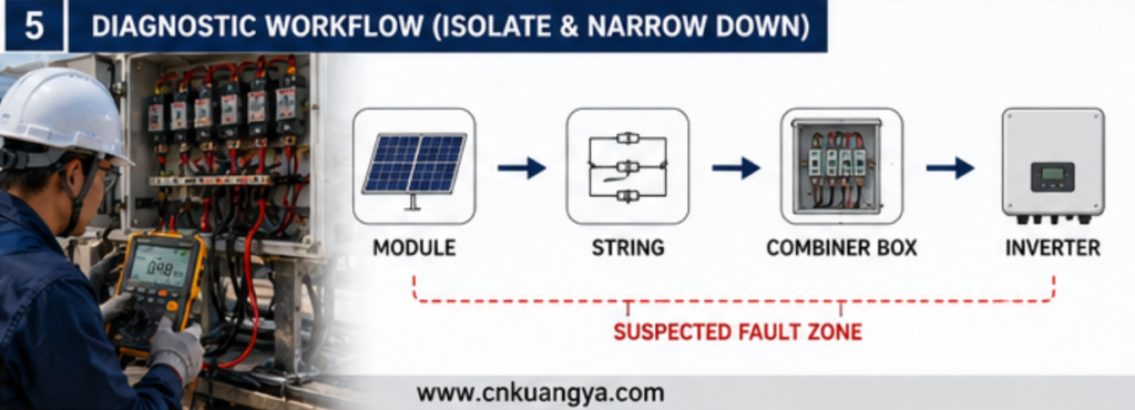
The key question is:
Is the fault in the inverter, main DC circuit, combiner box, string wiring or module section?
Large systems should be progressively divided into smaller electrical sections.
The objective is to determine:
Fault remains → problem is still inside the connected section
ou
Fault disappears → investigate the isolated section
This is more efficient than testing every module immediately.
When multiple strings are available, compare the suspected string with healthy strings.
Useful comparisons may include:
The objective is to identify the abnormal branch.
Prioritize locations such as:
Visual inspection should support electrical testing rather than replace it.
Once a problematic string is identified, divide the string or circuit into smaller sections where the system design and safe procedures allow.
This transforms:
“The entire PV plant has an insulation fault.”
into:
“The problem is located within this specific section.”
That is the central principle of efficient fault localization.
After identifying the fault source:
Then verify that the system has returned to an acceptable condition before normal operation.
An intermittent fault creates a dangerous temptation.
The technician resets the inverter.
The system starts.
The service ticket is closed.
Then the alarm returns after the next rain.
Restarting may temporarily restore generation, but it does not answer:
Repeated resets can turn a diagnosable early-stage problem into a more expensive failure.
Avoid:
Connectors should not carry unnecessary cable weight or remain in positions where water and contamination can accumulate.
Combiner boxes and other outdoor enclosures require:
Heavy rain and extreme environmental conditions can reveal developing insulation weaknesses.
Do not wait until an inverter refuses to start.
Periodic inspection and testing can help identify deterioration before it becomes a prolonged production problem.
IEC 62446-2 specifically addresses preventive, corrective and performance-related maintenance of grid-connected PV systems, including maintenance for reliability, safety, fire prevention and troubleshooting.
Experienced troubleshooting teams do not look only at the alarm.
They look at the pattern.
| Fault Pattern | Possible Direction |
|---|---|
| Only after rain | Moisture or ingress |
| Mainly early morning | Condensation-sensitive leakage |
| One specific string | Local string or module fault |
| Entire array | Common DC equipment or distributed leakage |
| After maintenance | Installation or reconnection issue |
| After electrical storm | Inspect affected protective equipment and connected circuits |
| Gradually increasing frequency | Progressive deterioration |
This table is not a substitute for testing.
Its purpose is to help determine where investigation should begin.
It generally means that the electrical isolation between the live PV DC circuit and earth or other conductive parts is lower than the equipment or system expects.
The cause must be identified through inspection and testing.
Moisture may create or strengthen an unintended leakage path in:
The fact that the fault disappears after drying does not mean the system is permanently repaired.
Sim.
Possible sources can include the module junction box, external leads or deterioration of the module insulation system.
Normal open-circuit voltage alone does not prove healthy insulation.
A damaged or degraded device connected to the DC protection circuit may need to be considered during diagnosis.
The device should be tested or replaced appropriately rather than permanently removed from the protection system.
Potentially.
Moisture, contamination, heat damage or internal electrical degradation may affect the condition of the device.
Temperature and moisture conditions may change.
Morning condensation or humidity can strengthen a leakage path that becomes less conductive as equipment dries and warms.
Not automatically.
The inverter may simply be detecting an upstream PV array problem.
The DC field should be systematically investigated before the inverter is assumed to be defective.
Não.
They are different electrical fault mechanisms, although deterioration can sometimes allow one fault condition to develop into another.
A Falha de resistência de isolamento fotovoltaico should not be treated as a mysterious inverter error.
It is an electrical condition that requires structured fault localization.
As causas mais comuns incluem:
The most effective diagnostic strategy is not random replacement.
It is:
Record → Isolate → Divide → Compare → Inspect → Test → Repair → Verify
This method turns a plant-wide alarm into a manageable electrical problem.
As photovoltaic systems become larger and DC architectures become more complex, insulation integrity remains a fundamental part of safe and reliable PV operation. Current IEC frameworks separately address PV array design, electrical installation, testing, inspection and maintenance, reinforcing the need to treat insulation performance as a system-level engineering issue rather than simply an inverter alarm.

