منطقة ونغ يانغ الصناعية يويتشينغ ونتشو 325000
ساعات العمل
من الاثنين إلى الجمعة: 7 صباحاً - 7 مساءً
عطلة نهاية الأسبوع 10 صباحاً - 5 مساءً
منطقة ونغ يانغ الصناعية يويتشينغ ونتشو 325000
ساعات العمل
من الاثنين إلى الجمعة: 7 صباحاً - 7 مساءً
عطلة نهاية الأسبوع 10 صباحاً - 5 مساءً


DC fuse sizing is not simply a matter of multiplying current by a safety factor and choosing the next fuse size. A correct selection must also satisfy the circuit’s DC voltage, conductor ampacity, equipment limits, temperature conditions and available fault current.
The method is also application-dependent. A photovoltaic string, a battery/inverter circuit and a general DC load do not necessarily use the same sizing rule. This guide explains the main checks and provides a practical calculator for preliminary fuse selection.
هام: The calculator below is a pre-selection tool, not a compliance determination. Always verify the adopted electrical code, equipment manufacturer’s instructions and the actual fuse datasheet before installation.
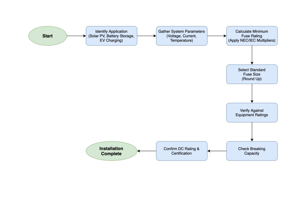
إذا كنت تريد أن تعرف how to choose the right fuse size أو how to calculate fuse rating for a DC circuit, start with the design current required by the application. For the common NEC PV source-circuit method, the familiar calculation is Isc × 1.5625. For battery/inverter and other DC circuits, use the manufacturer-specified or project-required design current and multiplier rather than assuming the same factor applies everywhere.
After the current calculation, adjust for the fuse manufacturer’s current rerating factor and select the next suitable available fuse size. Then verify four limits before final selection: equipment maximum fuse/OCPD rating, conductor ampacity, maximum DC voltage, and DC breaking capacity.
Quick formula for the common NEC PV method: Minimum current = Isc × 1.5625, then Required fuse nameplate current = Minimum current ÷ manufacturer rerating factor. The result is only a starting point; the selected fuse must still pass all equipment, conductor, voltage and fault-current checks.
| الخطوة | ما يجب القيام به |
|---|---|
| 1. Calculate design current | Use the correct current basis for the application: PV module Isc, manufacturer-specified battery/inverter current, or the DC load design current. |
| 2. Calculate the required fuse rating | Apply the code-, equipment- or project-specific sizing method and the fuse manufacturer’s temperature rerating factor. |
| 3. Verify the selected fuse | Check conductor ampacity, equipment maximum OCPD, DC voltage rating, breaking capacity and fuse category before final selection. |
Estimate a preliminary current rating, then check equipment, conductor, DC voltage and breaking-capacity limits.
Unlike AC, DC current does not naturally pass through zero every half-cycle. This makes interruption of a DC arc more demanding. A fuse used in a DC circuit therefore needs an appropriate DC voltage rating, breaking capacity and fuse category for the application.
Do not use a fuse in a DC circuit unless the fuse has a documented DC rating suitable for that circuit. Some fuse products carry both AC and DC ratings, while others are intended only for a specific application.
There is no single universal multiplier that correctly sizes every DC fuse. The first step is to identify the application and the design rule that applies to that circuit.
| التطبيق | Starting Current | Main Additional Checks |
|---|---|---|
| PV source circuit | Module/string Isc or another current value permitted by the adopted design method | Module maximum series fuse rating, conductor ampacity, cold-corrected string voltage, gPV fuse requirements |
| Battery / inverter | Manufacturer maximum continuous DC current or another approved design current | Manufacturer OCPD limits, conductor ampacity, battery fault current, DC breaking capacity |
| General DC load | Maximum circuit design current | Continuous-load rules where applicable, conductor protection, voltage and breaking capacity |
A commonly used NEC-based method for PV source-circuit fuse sizing applies two 125% factors. The first establishes a maximum circuit current from module Isc, and the second is used when sizing the overcurrent protective device under the applicable method.
Common calculation:
Minimum fuse current = Isc × 1.25 × 1.25 = Isc × 1.5625
This is the familiar “1.56 × Isc” rule used in many PV fuse-sizing guides. However, it should not be treated as a substitute for checking the NEC edition adopted by the Authority Having Jurisdiction (AHJ), the module listing and the actual project design.
After calculating the minimum current rating, the selected fuse must still satisfy the module maximum series fuse rating, conductor protection, temperature rerating, DC voltage and breaking-capacity requirements.
For IEC-based PV projects, avoid applying one fixed multiplier without checking the current design standard and the module/fuse manufacturer’s instructions. IEC 62548-1:2023 + AMD1:2025 is the current IEC reference for PV array design requirements, while IEC 60269-6:2010 + AMD1:2021 contains supplementary requirements for fuse-links used to protect photovoltaic strings and arrays.
The practical point is simple: determine the required design current using the applicable project method, then verify that the selected fuse is suitable for the module, conductor, maximum DC voltage and PV application. Do not hard-code an old IEC current range into a calculator and assume it applies to every project.
For a broader system-level explanation of PV array protection, voltage, strings and overcurrent design, see our IEC 62548 practical guide.
Use the current value required by the application and governing design method. For PV this may be based on module Isc. For battery/inverter circuits, prefer the manufacturer’s maximum continuous DC current or specified fuse/OCPD information rather than relying on a lower back-calculated value.
Apply the multiplier, continuous-load rule or design method required by the adopted code, equipment instructions or engineered design. For the common NEC PV method, this may be Isc × 1.5625. Other applications can use different rules.
Fuse current-carrying capability changes with ambient temperature. Use the rerating curve or factor supplied by the actual fuse manufacturer. Do not assume one universal temperature factor applies to all fuse series.
If the required current is 20A and the manufacturer’s current rerating factor at the actual ambient condition is 0.92, the required fuse nameplate current would be:
20A ÷ 0.92 = 21.74A
The next appropriate standard fuse size would then need to be checked against the equipment and conductor limits.
The selected fuse must not exceed the equipment manufacturer’s maximum permitted fuse or OCPD rating. For a PV module, this is commonly shown as the Maximum Series Fuse Rating on the module datasheet.
Verify the selected fuse against the conductor’s final allowable ampacity after all required correction and adjustment factors. Do not compare the fuse only with a simplified cable-size table.
The fuse voltage rating must be at least the maximum circuit voltage. In a PV string, calculate the maximum string voltage at the minimum design temperature using the module data and the applicable design method. A fuse should not be labelled “1000VDC suitable” for a design unless the calculated string voltage has actually been checked.
The fuse’s documented DC breaking capacity at the actual system voltage must be sufficient for the prospective short-circuit current at the fuse location. This is particularly important in battery systems, where fault current can be very high.
For battery systems, use the battery manufacturer’s specified short-circuit current or a properly engineered fault-current calculation. Do not select fuse breaking capacity from a simple nominal-voltage calculation using an estimated loop resistance.
Example data:
Step 1 – Common NEC PV current calculation:
12.8A × 1.5625 = 20.00A
Step 2 – Apply the fuse manufacturer’s current rerating factor:
20.00A ÷ 0.92 = 21.74A
The next suitable standard current rating in this example is 25A.
Preliminary result: 25A gPV fuse, with a DC voltage rating of at least 920VDC and adequate documented DC breaking capacity. The final product selection still depends on the module instructions, fuse datasheet and adopted code requirements.
With multiple parallel PV strings, healthy strings can feed reverse current into a faulted string. This is why string fusing becomes important as the number of parallel current sources increases.
However, avoid using “three strings always require a fuse” as a universal rule. The final requirement depends on the available reverse/fault current, conductor ampacity, module maximum overcurrent protection rating and the applicable electrical code.
If you are choosing the actual gPV fuse type, voltage class and form factor after completing the current calculation, see our solar fuse selection guide.
Battery fuse sizing requires special attention because the available short-circuit current can be much higher than the normal operating current.
Illustrative project data:
Current pre-selection:
125A × 1.25 = 156.25A
The next standard current size used in this example is 175A.
هام: This example does not mean every 125A inverter circuit should use a 175A fuse. The actual fuse rating and type must follow the inverter, battery, BMS, conductor and applicable installation requirements.
A fuse’s ampere rating does not tell you whether it can safely interrupt a fault at the system voltage. The DC voltage rating must be equal to or greater than the maximum voltage the fuse can experience.
For PV systems, the maximum string voltage can be substantially higher than the module’s STC Voc when the modules are cold. Calculate the maximum string voltage using the module temperature data and the project design method before choosing a 600VDC, 1000VDC or 1500VDC fuse.
Breaking capacity, also called interrupting rating, is the maximum prospective fault current that the fuse can safely interrupt under its stated conditions. Always compare DC breaking capacity at the relevant system voltage, not an AC value taken from the same product family.
If a battery manufacturer specifies an 18kA prospective short-circuit current, a fuse with only a 10kA documented DC breaking capacity at the system voltage would be inadequate. Select a product with a sufficient margin and verify the actual fuse datasheet.
| خطأ | ما أهمية ذلك | Better Practice |
|---|---|---|
| Using a fuse without a suitable DC rating | The fuse may not safely interrupt the DC arc at the actual system voltage. | Verify the documented DC voltage and DC breaking capacity. |
| Using one multiplier for every DC application | PV, battery and general DC circuits can follow different sizing methods. | Start with the applicable code, equipment instructions and circuit type. |
| Ignoring temperature rerating | Fuse current-carrying capability changes with ambient temperature. | Use the actual fuse manufacturer’s rerating curve or factor. |
| Exceeding equipment maximum OCPD | The fuse may no longer protect the equipment as intended. | Check the module, inverter, battery or equipment maximum fuse/OCPD rating. |
| Checking current but not voltage | A correctly sized ampere rating can still be unsafe if the DC voltage rating is too low. | Verify maximum circuit voltage, including cold PV Voc where applicable. |
| Guessing battery fault current | Battery fault current can be much higher than normal load current and depends on the actual battery system. | Use manufacturer short-circuit data or an engineered calculation. |
| Using AC interrupting data for a DC circuit | AC and DC interruption duties are not interchangeable. | Verify the documented DC breaking capacity at the actual system voltage. |
If a correctly selected fuse is already opening repeatedly, do not simply increase the ampere rating. Use our blown fuse troubleshooting guide to identify overload, short-circuit, connection and temperature-related causes first.
| Standard / Reference | ما أهمية ذلك |
|---|---|
| IEC 62548-1:2023 + AMD1:2025 | Current IEC PV array design requirements, including DC wiring and electrical protection provisions. |
| IEC 60269-6:2010 + AMD1:2021 | Supplementary requirements for fuse-links used to protect PV strings and PV arrays up to 1500V DC. |
| المادة 690 من قانون الكهرباء القومية | PV circuit current, conductor and overcurrent protection requirements for NEC jurisdictions. Verify the edition adopted by the AHJ. |
For a practical manufacturer reference on the commonly used NEC PV method and fuse temperature rerating, see the Littelfuse photovoltaic fuse sizing application guide.
Start with the correct design current, calculate the minimum fuse rating using the method required for the application, and then select a standard fuse size that still protects the conductor and equipment. The final fuse must also have a suitable DC voltage rating, breaking capacity and time-current characteristic.
There is no single formula for every DC circuit. For the common NEC PV method, the starting calculation is Isc × 1.5625. Battery/inverter and general DC circuits should use the design current and sizing method required by the equipment manufacturer, applicable code or project specification.
No. The required method depends on the application and governing rules. A PV source circuit, a battery/inverter circuit and a general DC load should not automatically use the same multiplier.
The familiar 1.56 value comes from two 125% factors: 1.25 × 1.25 = 1.5625. It is a common NEC-based PV source-circuit sizing method, but the final design must still follow the adopted NEC edition, equipment listing and AHJ requirements.
Only if that specific fuse also has a suitable documented DC voltage and interrupting rating for the application. Do not assume an AC-only rating is valid for DC.
The fuse DC voltage rating must be at least the maximum circuit voltage. For PV, use the maximum cold-corrected string voltage rather than the nominal system voltage alone.
Use the battery manufacturer’s prospective short-circuit current or a properly engineered fault-current calculation, then select a fuse whose documented DC breaking capacity at the actual system voltage is not less than the available fault current.
A gPV fuse-link is designed for photovoltaic protection. IEC 60269-6 provides supplementary requirements for fuse-links used to protect PV strings and arrays. The fuse must still be selected for the actual current, maximum DC voltage and fault conditions of the installation.
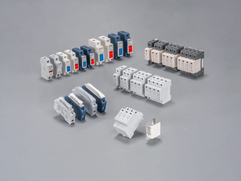
KUANGYA supplies DC fuse and fuse-holder solutions for photovoltaic and other DC protection applications. Explore our DC fuse products, أو اتصل بنا for model-specific ratings, available certifications, OEM options and application support.
Disclaimer: This article and calculator are for educational and preliminary selection purposes only. Electrical protection design must be verified by a qualified professional using the applicable electrical code, local requirements, equipment instructions and actual fuse datasheets.

