منطقة ونغ يانغ الصناعية يويتشينغ ونتشو 325000
ساعات العمل
من الاثنين إلى الجمعة: 7 صباحاً - 7 مساءً
عطلة نهاية الأسبوع 10 صباحاً - 5 مساءً
منطقة ونغ يانغ الصناعية يويتشينغ ونتشو 325000
ساعات العمل
من الاثنين إلى الجمعة: 7 صباحاً - 7 مساءً
عطلة نهاية الأسبوع 10 صباحاً - 5 مساءً
كان عامل تركيب طاقة شمسية متمرس، دعنا نسميه ديف، يواجه كابوسًا متكررًا. في نظام تجاري على السطح بقدرة 100 كيلوواط كان قد أكمله قبل ثلاثة أشهر، كانت الصمامات تنفجر في الأيام المشمسة تمامًا. كان العميل يخسر الإنتاج، وكان فريق ديف يهدر الوقت والمال على مكالمات الخدمة لاستبدال الصمامات 20 أمبير. كان التشخيص الأولي عبارة عن مجموعة سيئة من الصمامات. ولكن بعد الاستدعاء الثالث، اتضحت المشكلة الحقيقية. فقد تم تصميم النظام بلوحات جديدة عالية الكفاءة بقدرة 550 واط مع تيار دائرة قصر (Isc) يبلغ 13.9 أمبير. قام مهندس ديف الرئيسي، معتمدًا على العادات القديمة، بتحديد حجم صمامات السلسلة باستخدام مضاعف بسيط 1.25 ضعفًا، حيث وصل إلى 17.4 أمبير وتقريبها إلى مصهر قياسي 20 أمبير.
ما فاته هو الحساب الكامل الذي يفرضه الكود الذي يأخذ في الحسبان كلاً من الحمل المستمر و طفرات الإشعاع الشمسي في العالم الحقيقي - وهي الظروف التي يمكن أن تنتج فيها الألواح المشبعة بالشمس بشكل مؤقت أعلى بكثير من تصنيفها في اللوحة. في فترات ما بعد الظهيرة الواضحة والمشرقة تلك، تجاوز تيار المصفوفة 20 أمبير لفترة طويلة بما يكفي لإجهاد عناصر الصمامات. كان الإصلاح عبارة عن إعادة صمامات كاملة لصناديق التجميع إلى 25 أمبير الصمامات, ولكن الضرر قد وقع: عميل محبط، وهوامش ربح متآكلة، ودرس مستفاد بصعوبة.
“قريب بما فيه الكفاية” عبارة خطيرة في التصميم الكهربائي. في عالم أنظمة التيار المباشر عالية الطاقة (DC) - بدءًا من مزارع الطاقة الشمسية على نطاق المرافق إلى تخزين طاقة البطاريات (BESS) والشواحن السريعة للمركبات الكهربائية (EV) - لا يعد تحديد حجم الصمامات بدقة ومتوافق مع الكود توصية؛ بل هو ركيزة غير قابلة للتفاوض للسلامة والموثوقية والجدوى المالية. يوفر هذا الدليل منهجية احترافية خطوة بخطوة للحصول على الحجم الصحيح في كل مرة.
قبل الغوص في الحسابات، من الضروري فهم سبب كون الحماية من التيار الزائد للتيار المستمر أكثر صعوبة بشكل أساسي من نظيرتها للتيار المتردد. يكمن الفرق في فيزياء القوس الكهربائي.
في دائرة التيار المتردد، يمر التيار بشكل طبيعي عبر الصفر 100 أو 120 مرة كل ثانية. يوفر هذا العبور الصفري فرصة لحظية لإطفاء القوس - جسر البلازما الذي يتشكل عندما يذوب عنصر الصمامات. صُممت صمامات التيار المتردد للاستفادة من مفتاح “الإيقاف” المتكرر هذا.
العاصمة لا هوادة فيها. ليس له تقاطع صفري. عندما ينفتح صمام التيار المستمر، ينشأ قوس مستمر عالي الطاقة. هذا القوس هو في الأساس عبارة عن نفاثة بلازما بدرجة حرارة تتجاوز 10000 درجة مئوية. ولإخماده، يجب أن يكون مصهر التيار المستمر قويًا بما يكفي لتمديد القوس حتى يتجاوز الطلب على الجهد الكهربائي للنظام، وفي الوقت نفسه يمتص طاقة حرارية هائلة لتبريد البلازما. وهذا هو السبب في أن صمامات التيار المستمر (gPV) وغيرها من الصمامات المصنفة للتيار المستمر غالبًا ما تحتوي على حشو رمل كوارتز متخصص، والذي يذوب في مادة تشبه الزجاج تسمى الفولجوريت، مما يخنق القوس.
يعد استخدام مصهر تيار متردد في تطبيق تيار مستمر خطأ كارثي. من المحتمل أن يفشل في إزالة العطل، مما يؤدي إلى حدوث قوس كهربائي مستمر، وانفجار محتمل لجسم الصمامات، وخطر نشوب حريق كبير. لتحديد مصهر تيار مستمر بشكل صحيح، يجب أن تتقن أربعة معايير رئيسية:
إن “المضاعف 1.56” هو حجر الزاوية في تحديد حجم صمامات التيار المستمر في أمريكا الشمالية، ولكن العديد من المحترفين يسيئون تطبيقه أو لا يفهمون أصله. إنه ليس رقمًا اعتباطيًا؛ إنه عامل أمان مشتق مباشرةً من الكود الوطني للكهرباء (NEC).
يأتي المعامل 1.56 من تطبيق مضاعفين منفصلين 125% على التوالي، كما هو منصوص عليه في المادة 690 من NEC لأنظمة الطاقة الشمسية الكهروضوئية.
الجمع بين هاتين الخطوتين يعطينا الصورة الكاملة:
الحد الأدنى لتقييم الصمامات = (Isc × 1.25) × 1.25 = Isc × 1.5625
لأغراض عملية، يتم تقريبها إلى 1.56. بعد حساب هذا الحد الأدنى من التقييم، يجب عليك دائمًا تقريب لأعلى إلى حجم المصهر القياسي التالي (على سبيل المثال، 10 أمبير، 15 أمبير، 20 أمبير، 25 أمبير، 30 أمبير).
في حين أن لجنة الكهرباء الوطنية توفر مضاعفًا إلزاميًا واضحًا، فإن المعيار الدولي IEC 62548 يوفر نطاقًا أكثر مرونة. ينص معيار IEC على أن تصنيف الصمامات (I_n) يجب أن يقع بين التيار التصميمي (I_B) وسعة الكابل (I_z)، باتباع القاعدة I_B ≤ I_n ≤ I_z.
بالنسبة لحماية السلسلة الكهروضوئية، توصي المواصفة القياسية IEC 62548 بتحديد حجم الصمامات بين 1.5 و2.4 ضعف قيمة Isc للوحدة.
يسمح هذا النطاق للمصممين بتحسين الحماية بناءً على الظروف البيئية المحلية ودرجة الحرارة وخصائص الوحدة المحددة. ومع ذلك، بالنسبة للمشاريع الخاضعة لاختصاص NEC، فإن المضاعف 1.56 إلزامي.
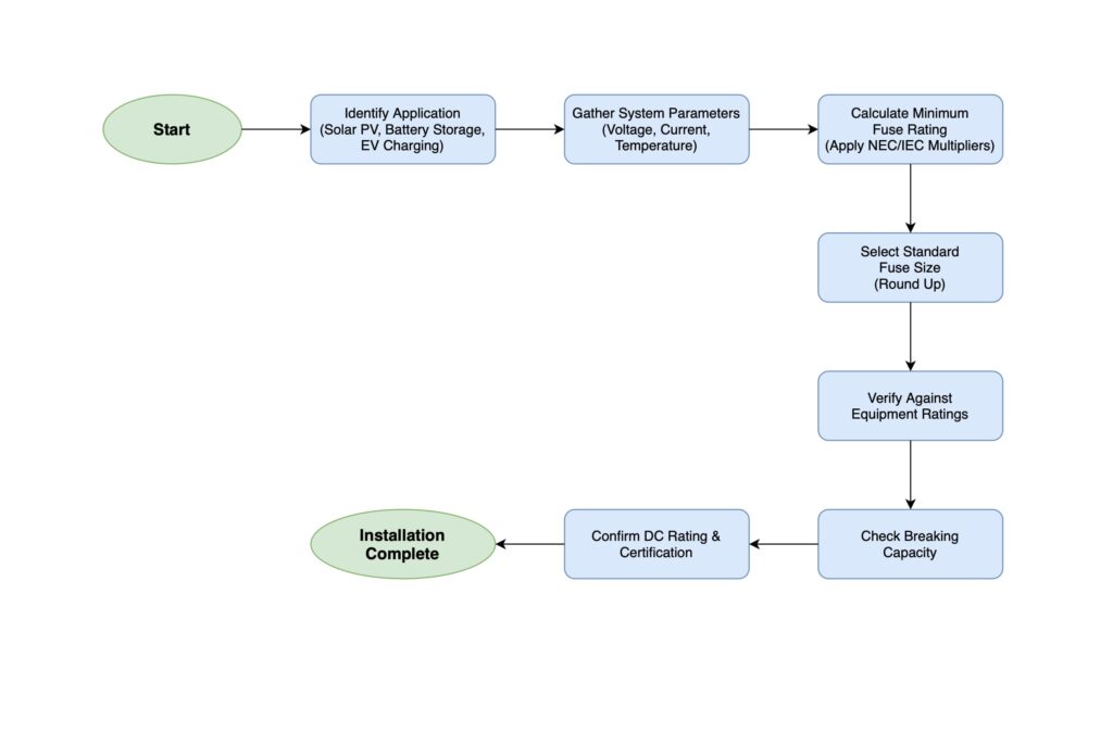
لا تفكر في هذا الأمر كأداة مؤتمتة، بل كعملية يدوية من ست خطوات تضمن أخذ كل متغير مهم بعين الاعتبار. سيؤدي اتباع سير العمل هذا إلى منع الأخطاء ويؤدي إلى تصميم آمن وموثوق ومتوافق مع التعليمات البرمجية.
الخطوة 1: تحديد الحد الأقصى للتيار التصميمي
حدِّد الحد الأقصى للتيار المستمر الذي ستحمله الدائرة الكهربية.
الخطوة 2: تطبيق عوامل تكييف درجة الحرارة
يتم تصنيف الصمامات لدرجة حرارة محيطة محددة (عادةً 25 درجة مئوية أو 40 درجة مئوية). إذا تم تركيبها في بيئة أكثر حرارة، مثل صندوق تجميع مشمس على السطح، فإن قدرتها الفعالة على حمل التيار تنخفض. يجب عليك الرجوع إلى ورقة بيانات الشركة المصنعة للصمامات لمعرفة منحنيات أو جداول الاستثناءات. على سبيل المثال، قد يكون لمصهر بقوة 20 أمبير في بيئة درجة حرارتها 65 درجة مئوية تصنيف فعال يبلغ 17.4 أمبير فقط. قد تحتاج إلى اختيار مصهر أكبر للتعويض عن ذلك.
الخطوة 3: تطبيق مضاعف الرمز ذي الصلة
قم بتطبيق عامل الأمان المطلوب بناءً على الكود الحاكم الخاص بك.
الخطوة 4: حدد حجم المصهر القياسي التالي
بعد تطبيق المضاعفات، سيكون لديك الحد الأدنى المطلوب من تصنيف الصمامات. يجب عليك تحديد قياسي حجم المصهر المتاح تجاريًا يساوي أو أكبر من القيمة المحسوبة. على سبيل المثال، إذا أسفرت حساباتك عن تصنيف 22.54 أمبير كحد أدنى، فيجب عليك اختيار مصهر 25 أمبير.
الخطوة 5: التحقق من حماية الموصلات والمعدات
للصمام وظيفتان: حماية السلك وحماية المعدات.
الخطوة 6: تحقق من تصنيف المقاطعة (kA)
وأخيراً، تحقق من أن تصنيف المقاطعة للمصهر (kA) أكبر من تيار الدائرة القصيرة المتاح في تلك النقطة في النظام. وهذا أمر بالغ الأهمية بشكل خاص لأنظمة البطاريات، والتي يمكن أن توفر تيارات أعطال هائلة. تقدير سريع لتيار الدائرة القصيرة المحتمل للبطارية (I_sc) هو I_sc = جهد البطارية / مقاومة الحلقة الكلية. إذا كان I_sc المحسوب 16,000 أمبير (16kA)، فإن الصمامات ذات معدل المقاطعة 10kA غير كافية ويمكن أن تتعطل بعنف.
دعونا نطبق هذه العملية المكونة من ست خطوات على ثلاثة تطبيقات شائعة للتيار المستمر عالي الطاقة.
بالنسبة للمصفوفات الشمسية التي تحتوي على ثلاثة سلاسل أو أكثر على التوازي، تتطلب NEC 690.9 (A) أن يكون لكل سلسلة مصهر منفرد. وهذا يمنع حدوث عطل في سلسلة واحدة من سحب تيار عكسي هائل من السلاسل السليمة.
السيناريو تصميم سلسلة صمامات تصميم لنظام تجاري على السطح باستخدام ألواح بقدرة 450 واط.
الحساب:
الحد الأدنى للمعدل المطلوب = 12.8 أمبير × 1.56 = 19.97 أمبيرتصنيف الصمامات الفعال = 20 أمبير × 0.92 (عامل الاستبعاد) = 18.4 أمبيرتصنيف الصمامات الفعال = 25 أمبير × 0.92 = 23 أمبير9 خيوط × 12.8 أمبير × 115 أمبير. تتمتع صمامات gPV القياسية بتصنيف مقاطعة يبلغ 10 كيلو أمبير أو أعلى، وهو أكثر من كافٍ. ✓الاختيار النهائي: صمام 25 أمبير، 1000 فولت فولت تيار مستمر بقوة 25 أمبير، 1000 فولت تيار مستمر.
يتعلق الصمامات لبنك بطاريات الليثيوم أيون الكبير في المقام الأول بالحماية من حدوث ماس كهربائي كارثي. يجب أن يكون المصهر قادراً على مقاطعة عشرات الآلاف من الأمبيرات.
السيناريو حدد مصهر التيار المستمر الرئيسي لبنك بطارية LiFePO4 بجهد 48 فولت، 400 أمبير في الساعة متصل بعاكس/شاحن بقوة 5,000 واط.
الحساب:
أقصى سحب للطاقة = 5000 واط / 0.95 (الكفاءة) = 5263 واطأقصى تيار تيار مستمر = 5263 وات / 44 فولت (جهد منخفض) = 119.6 أمبيرالحد الأدنى للتقييم المطلوب = 119.6 أمبير × 1.25 = 149.5 أمبيرالاختيار النهائي: 150 أمبير، صمامات من الفئة T (≥20 كيلو أمبير تصنيف المقاطعة).
تعد أجهزة الشحن السريع للتيار المستمر فريدة من نوعها لأنها تحتوي على إلكترونيات طاقة حساسة (IGBTs أو SiC MOSFETs) التي يمكن أن تتلف بسبب التيار الزائد في أجزاء من الثانية. ولا تتعلق الحماية هنا بمنع حرائق الأسلاك بقدر ما تتعلق بحماية وحدات أشباه الموصلات باهظة الثمن. وهذا يتطلب صمامات فائقة السرعة.
السيناريو قياس حجم فتيل خرج التيار المستمر لوحدة طاقة واحدة بقدرة 50 كيلوواط في شاحن سريع بقدرة 150 كيلوواط تيار مستمر.
الحساب:
أقصى تيار = 50,000 واط / 200 فولت = 250 أمبيرتصنيف الصمامات المستهدفة = 250 أمبير × 1.4 = 350 أمبير38,000 متر مربع < 50,000 متر مربع. سوف يحمي المصهر IGBT. ✓الاختيار النهائي: 350 أمبير، 1000 فولت تيار مستمر (أشباه الموصلات) مصهر (350 أمبير، 1000 فولت تيار مستمر) مع تصنيف مقاطعة ≥50 كيلو أمبير و I²t < 50,000 A²s.
حتى مع وجود عملية متينة، يمكن أن تؤدي الأخطاء الشائعة إلى الإضرار بسلامة النظام وموثوقيته. فيما يلي ملخص للأخطاء الأكثر شيوعًا وكيفية الوقاية منها.
| بيتفول | لماذا هو خطير | كيفية تجنب ذلك |
|---|---|---|
| استخدام صمامات ذات تصنيف تيار متردد في دائرة تيار مستمر | لا يمكن لصمامات التيار المتردد إطفاء قوس التيار المستمر، مما يؤدي إلى استمرار الانحناء وتمزق الصمامات وارتفاع خطر نشوب حريق. | استخدم دائمًا الصمامات التي تحمل علامة جهد تيار مستمر وتقييم المقاطعة (على سبيل المثال، VDC، gPV، الفئة T). |
| تجاهل تكييف درجة الحرارة | الصمامات في بيئة ساخنة (على سبيل المثال، صندوق التجميع على السطح) لها سعة تيار منخفضة وستتسبب في حدوث انقطاعات مزعجة إذا لم يكن حجمها مناسبًا للتعويض. | تحقق من ورقة بيانات الشركة المصنّعة لمعرفة منحنيات الاستنقاص من درجة الحرارة واضبط اختيار الصمامات وفقًا لذلك. |
| تصنيف المقاطعة الأقل من المطلوب (كيلو أمبير) | إذا كان تصنيف مقاطعة الصمامات أقل من تيار العطل المتاح، يمكن أن ينفجر أثناء حدوث ماس كهربائي. | قم بحساب أو تقدير تيار الدائرة القصيرة المحتمل، خاصةً بالنسبة لبنوك البطاريات، واختر الصمامات التي تتجاوز هذه القيمة. |
| تجاوز الحد الأقصى لتقييم الصمامات للوحدة النمطية | يؤدي تحديد حجم الصمام فوق الحد الأقصى لمعدل الصمامات المتسلسلة للوحة الشمسية إلى إبطال الضمان وإلغاء حماية اللوحة نفسها. | تحقق دائمًا من تصنيف الصمامات الذي اخترته مقابل مواصفات الشركة المصنعة للمعدات. دع القيمة الأقل تملي عليك الحد الأقصى للحجم. |
| عدم تطابق الصمامات ومقياس الأسلاك | قم بتركيب مصهر بمعدل أمبيرية أعلى من السلك المتصل به. يمكن أن يسخن السلك ويذوب قبل أن ينفجر المصهر. | تأكد من أن تصنيف الصمامات دائمًا أقل من أو يساوي سعة الموصل الذي تحميه وفقًا لـ NEC 240.4. |
| استخدام سرعة الصمامات الخاطئة | استخدام صمامات بطيئة ذات تأخير زمني بطيء لحماية الإلكترونيات الحساسة، أو صمامات سريعة المفعول على دائرة محرك ذات تيار تدفق عالي. | قم بمطابقة منحنى التيار الزمني للصمامات مع التطبيق: gPV للطاقة الشمسية، aR لأشباه الموصلات، التأخير الزمني للمحركات، إلخ. |
التحجيم الدقيق لصمامات التيار المستمر هو نظام وليس رقمًا واحدًا. إنها عملية منهجية توازن بين متطلبات الكود والواقع البيئي والاحتياجات الوقائية المحددة لكل مكون في السلسلة - من الموصل إلى مصدر الطاقة نفسه. من المضاعف 1.56 ضعفاً في الطاقة الشمسية إلى سعة التقطيع الحرجة للبطاريات وأوقات الاستجابة بالميكروثانية اللازمة لشواحن السيارات الكهربائية، فإن فهمها بشكل صحيح هو السمة المميزة للمحترف الكهربائي الحقيقي. إنه الفرق بين النظام الذي يتم تركيبه فقط والنظام الذي تم تصميمه لعقود من الأداء الآمن والموثوق.
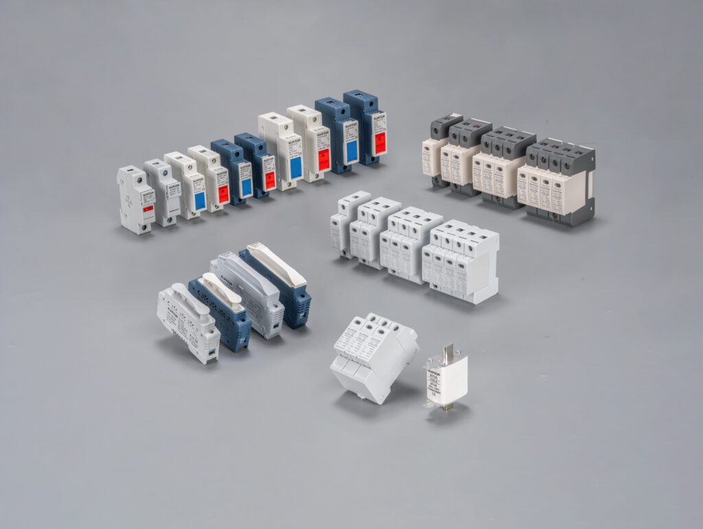
هل أنت مستعد لتطبيق هذه المبادئ بمكونات يمكنك الوثوق بها؟ استكشف مجموعة كوانجيا الكاملة من صمامات التيار المستمر المتوافقة مع NEC و IEC للعثور على الحماية الدقيقة التي يتطلبها مشروعك. للتطبيقات المعقدة أو للتحقق من حساباتك, اتصل بفريقنا الهندسي للحصول على إرشادات الخبراء في مشروعك القادم.
تنويه: المعلومات الواردة في هذه المقالة هي لأغراض تعليمية فقط. الأعمال الكهربائية خطيرة ويجب ألا يقوم بها إلا محترفون مؤهلون. استشر دائمًا أحدث إصدار من الكود الكهربائي الوطني (NEC)، ومعايير IEC ذات الصلة، والقوانين المحلية التي تطبقها السلطة ذات الاختصاص القضائي (AHJ)، ومواصفات الشركة المصنعة للمعدات قبل تصميم أو تركيب أي نظام كهربائي.
