منطقة ونغ يانغ الصناعية يويتشينغ ونتشو 325000
ساعات العمل
من الاثنين إلى الجمعة: 7 صباحاً - 7 مساءً
عطلة نهاية الأسبوع 10 صباحاً - 5 مساءً
منطقة ونغ يانغ الصناعية يويتشينغ ونتشو 325000
ساعات العمل
من الاثنين إلى الجمعة: 7 صباحاً - 7 مساءً
عطلة نهاية الأسبوع 10 صباحاً - 5 مساءً

يمكن أن تتعرض مصفوفات الألواح الكهروضوئية ومسارات كابلات التيار المستمر الطويلة الخاصة بها لزيادات جهد عابرة ناتجة عن أحداث البرق والتبديل. يجب أن يتبع اختيار ووضع واقيات زيادة الطاقة الكهروضوئية مخاطر البرق في الموقع، وترتيب العاكس والمصفوفة، ومسار كابل التيار المستمر، والقواعد المحلية المعمول بها. قد يكون واقي زيادة الطاقة الكهروضوئي بالقرب من العاكس كافياً لمسار تيار مستمر قصير؛ قد تتطلب المسارات الأطول واقي زيادة طاقة إضافي بالقرب من المصفوفة أو صندوق التجميع. انظر دليل التركيب الكهربائي لمواقع واقيات زيادة الطاقة الكهروضوئية.
يشرح هذا الدليل كيفية تقييم الحاجة إلى واقيات زيادة الطاقة الكهروضوئية واختيار واقيات زيادة الطاقة المصنفة للتيار المستمر للمواقع المناسبة. يغطي معيار المنتج IEC 61643-31 واقيات زيادة الطاقة المتصلة بالجانب المستمر لمولدات ومحولات الطاقة الكهروضوئية؛ يتم تناول تصميم و تنسيق التركيب بشكل منفصل بواسطة IEC 61643-32.
تُعد مصفوفات الطاقة الشمسية بطبيعة تصميمها مغناطيسات لجذب الصواعق. وإليك سبب كون سلاسل الألواح الكهروضوئية لديك عرضة بشكل خاص لأحداث زيادة التيار:
التعرض المرتفع: يتم تركيب الألواح الشمسية عمداً في مواقع مفتوحة ومرتفعة للحصول على أقصى قدر من التعرض لأشعة الشمس، وهي نفس الخصائص التي تجعل الهياكل عرضة لجذب الصواعق. يمكن أن تكون التركيبات فوق الأسطح هي أعلى نقطة في المبنى، بينما تفتقر المصفوفات المثبتة على الأرض في الحقول المفتوحة إلى الحد الأدنى من الحماية الطبيعية من الصواعق.
كابلات التيار المستمر الطويلة كأنظمة هوائيات: تعمل كابلات التيار المستمر التي تربط سلاسل الألواح الشمسية (PV strings) كهوائيات ضخمة، حيث تلتقط التداخل الكهرومغناطيسي الناتج عن ضربات البرق القريبة. حتى الضربات غير المباشرة (البرق الذي يضرب الأرض أو الهياكل المجاورة ضمن نطاق 2 كم) يمكن أن تحفز ارتفاعات في الجهد تتجاوز 6000 فولت على الكابلات غير المحمية.
نقاط دخول متعددة: على عكس الأنظمة الكهربائية التقليدية التي تحتوي على نقطة توصيل واحدة بمصدر الطاقة، تمتلك المصفوفات الشمسية عشرات أو مئات المسارات المحتملة لدخول الارتفاعات المفاجئة في الجهد؛ حيث تمثل كل سلسلة مساراً للطاقة المدمرة للوصول إلى معدات العاكس (Inverter) باهظة الثمن.
استمرار القوس الكهربائي للتيار المستمر: عندما تتسبب الارتفاعات المفاجئة في حدوث قوس كهربائي في أنظمة التيار المستمر، فإن القوس لا ينطفئ ذاتياً عند نقطة عبور الصفر كما هو الحال في أنظمة التيار المتردد. يمكن لأقواس التيار المستمر أن تستمر وتتفاقم، مما يخلق مخاطر نشوب حرائق وأضراراً كارثية في المعدات.
فكر في مصفوفة الطاقة الشمسية الخاصة بك كحقل من مانعات الصواعق المتصلة مباشرة بمعدات إلكترونية دقيقة؛ فبدون الحماية المناسبة، المسألة ليست ما إذا إذا كنت ستتعرض لأضرار ناتجة عن ارتفاع الجهد، بل متى سيحدث ذلك. عندما.
تتجاوز عواقب عدم كفاية الحماية من زيادة التيار في سلاسل الألواح الكهروضوئية مجرد تلف المعدات الفوري:
عندما تنتقل زيادة التيار عبر سلاسل الألواح الكهروضوئية غير المحمية، تكون الخسائر الأولى عادةً:
حتى الارتفاعات المفاجئة في الجهد التي لا تسبب فشلاً فورياً يمكن أن تؤدي إلى حدوث تشققات دقيقة في الخلايا الشمسية، مما يسرع من التدهور على المدى الطويل. تظهر الدراسات أن الوحدات المعرضة لأحداث ارتفاع الجهد المتكررة دون حماية كافية يمكن أن تفقد 15-25% إضافية من كفاءتها على مدار عمرها الافتراضي مقارنة بالأنظمة المحمية.
| حجم النظام | متوسط قيمة الإنتاج اليومي | تكلفة التوقف عن العمل لمدة 3 أسابيع | الإيرادات المفقودة (الأثر السنوي) |
|---|---|---|---|
| 100 كيلوواط تجاري | 35-50 دولاراً في اليوم | $735-1,050 | مراعاة الأنماط الموسمية |
| 500 كيلوواط صناعي | 175-250 دولاراً في اليوم | $3,675-5,250 | بالإضافة إلى غرامات رسوم الطلب |
| 1 ميجاواط على مستوى المرافق | 350-500 دولار في اليوم | $7,350-10,500 | بالإضافة إلى غرامات الأداء الخاصة باتفاقية شراء الطاقة (PPA) |
| محطة طاقة شمسية بقدرة 5 ميجاوات | 1,750-2,500 دولار/يوم | $36,750-52,500 | بالإضافة إلى غرامات عقود المرافق |
نصيحة احترافية: لا تغطي العديد من وثائق التأمين أضرار الارتفاع المفاجئ في الجهد الكهربائي إذا لم تتمكن من إثبات أن أجهزة الحماية من الارتفاع (SPD) المطلوبة وفقاً للكود قد تم تركيبها وصيانتها بشكل صحيح؛ احرص دائماً على توثيق تركيبات أجهزة الحماية من الارتفاع بصور مؤرخة وتقارير التشغيل.
إليك البند الذي يغفله الكثيرون في ضمانات الشركات المصنعة: تتطلب معظم ضمانات العواكس (Inverters) والألواح صراحةً “تركيب حماية مناسبة من الارتفاع المفاجئ في الجهد وفقاً للأكواد الكهربائية المحلية ومعيار IEC 61643-31”. إذا لم تتمكن من إثبات تركيب أجهزة الحماية المناسبة، فقد تفقد ضمانات تقدر قيمتها بعشرات الآلاف من الدولارات.
إن فهم مسار زيادة التيار عبر نظام الطاقة الكهروضوئية الخاص بك يوضح سبب أهمية الحماية على مستويات متعددة: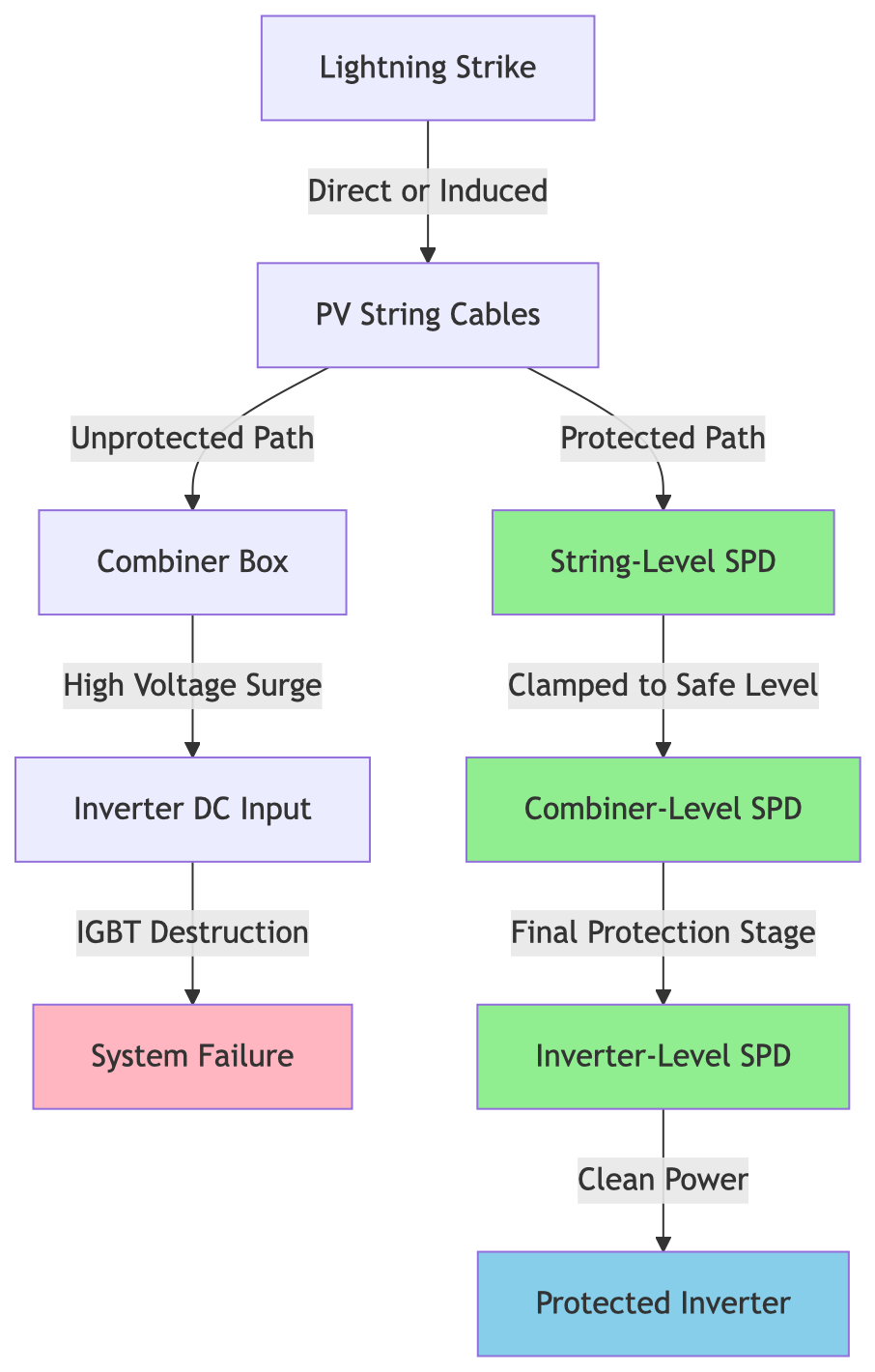
تتبع الحماية الفعالة من زيادة التيار في سلاسل الألواح الكهروضوئية (PV) تسلسلاً منسقاً للحماية؛ تخيلها كسلسلة من الحواجز الدفاعية، صُمم كل منها للتعامل مع مستويات تهديد محددة:
خط الدفاع الأول (على مستوى السلسلة): تعمل أجهزة الحماية من زيادة التيار (SPDs) من النوع 2 المثبتة عند أو بالقرب من مصفوفة الألواح الكهروضوئية على التعامل مع طاقة الاندفاع الأولية. تقوم هذه الأجهزة بتثبيت الجهد العابر العالي قبل انتقاله عبر مسافات الكابلات الطويلة حيث يمكن أن تتراكم الطاقة.
الخط الثاني (صندوق التجميع): توفر أجهزة حماية إضافية من النوع 2 حماية احتياطية وتتعامل مع أي زيادات متبقية في التيار قد تكون تجاوزت أجهزة مستوى السلسلة أو دخلت عبر مسارات أخرى.
الخط النهائي (مدخل العاكس): توفر أجهزة الحماية من النوع 2 أو أجهزة الحماية الدقيقة المثبتة عند مدخل التيار المستمر للعاكس خط الدفاع الأخير، مما يضمن وصول طاقة نظيفة فقط إلى المكونات الإلكترونية الحساسة.
المبدأ الأساسي: تنسيق واقيات زيادة الطاقة باستخدام وثائق الجهاز والعاكس وإرشادات التركيب المعمول بها. يُستخدم عتبة مسار الكابل التقريبية البالغة 10 أمتار لتقييم ما إذا كان واقي زيادة طاقة إضافي مطلوباً بالقرب من مصفوفة الألواح الكهروضوئية؛ فهي ليست الحد الأدنى العام للفصل بين مراحل واقي زيادة الطاقة.
لا تعامل الاستشهاد بـ NEC في الإصدار السابق لهذه المقالة على أنه تفويض شامل لواقي زيادة الطاقة. تحقق من إصدار NEC المعتمد في الولاية القضائية للمشروع، والتعديلات المحلية، وتصميم النظام. بالنسبة للتصاميم المستندة إلى IEC،, IEC 61643-31 يحدد المتطلبات والاختبارات لواقيات زيادة الطاقة الكهروضوئية للتيار المستمر، بينما IEC 61643-32 عناوين الاختيار والتركيب والتنسيق. ما يلي هو فحوصات تصميمية، وليس متطلبات عامة للكود:
يحدد IEC 61643-31 المتطلبات وطرق الاختبار لواقيات زيادة التيار للتيار المستمر الكهروضوئي. يغطي IEC 61643-32 التطبيق والاختيار والتركيب والتنسيق.
نصيحة احترافية: أثناء مراجعات التصاريح وعمليات التفتيش، فإن وجود أجهزة حماية من زيادة التيار (SPDs) على مستوى السلاسل (String-level) ومصنفة ومركبة بشكل صحيح يظهر العناية الهندسية الواجبة ويمكن أن يسرع من عمليات الموافقة؛ حيث يبحث المفتشون عن ذلك كعلامة على جودة التركيب.
إن اختيار حماية مناسبة من زيادة التيار (Surge Protection) لسلاسل الألواح الكهروضوئية ليس ضرباً من التخمين، بل اتبع هذا النهج المنهجي لتحديد الأجهزة المناسبة في كل مرة:
يجب أن يتجاوز أقصى جهد تشغيل مستمر (Uc) لجهاز الحماية من زيادة التيار (SPD) أقصى جهد للدائرة المفتوحة (Voc) الذي يمكن أن ينتجه نظامك تحت أي ظروف.
معادلة الحساب:
Uc(min) = Voc(STC) × معامل تصحيح درجة الحرارة × هامش الأمانمعامل تصحيح درجة الحرارةملاحظة: مقابل كل 10 درجات مئوية تحت 25 درجة مئوية (STC)، يزداد جهد الدائرة المفتوحة (Voc) بنسبة تقريبية تتراوح بين 0.35% إلى 0.40% لكل درجة مئوية للوحدات البلورية السيليكونية النموذجية.
مثال على الحساب:
الاختيار: اختر جهاز حماية من اندفاع التيار (SPD) بجهد تشغيل مستمر (Uc) أكبر من أو يساوي 1,500 فولت تيار مستمر لهذا النظام الاسمي بجهد 1000 فولت.
النتيجة الرئيسية: لا تقم أبداً باختيار أجهزة الحماية من اندفاع التيار (SPD) بناءً على الجهد الاسمي للنظام فقط. احرص دائماً على حساب أسوأ حالة لجهد الدائرة المفتوحة (Voc) بما في ذلك تأثيرات درجات الحرارة، وأضف هامش أمان بنسبة 15-20% لمنع تدهور أداء جهاز الحماية أثناء ظروف البرودة والإشعاع الشمسي العالي.
مستوى حماية الجهد (Up) هو أقصى جهد سيظهر عند المعدات المحمية أثناء تشغيل جهاز الحماية من اندفاع التيار (SPD). يجب أن يكون هذا المستوى أقل من جهد التحمل الخاص بمعداتك.
معايير الاختيار:
Up(SPD) < 0.8 × جهد تحمل المعداتبالنسبة لمحولات السلسلة (String Inverters) النموذجية:
قيم (Up) الموصى بها لأجهزة الحماية من اندفاع التيار على مستوى السلسلة:
نصيحة احترافية: توفر قيم Up المنخفضة حماية أفضل ولكن قد يكون لها عمر افتراضي أقصر بسبب التنشيط المتكرر. وازن بين مستوى الحماية وتكرار الصواعق المتوقع في موقعك؛ فالمناطق ذات النشاط البرقي العالي قد تتطلب مواصفات أكثر قوة.
يجب أن تتعامل أجهزة الحماية من الصواعق (SPDs) الخاصة بسلاسل الألواح الشمسية (PV) مع كل من الصواعق المباشرة وغير المباشرة. التصنيفات الرئيسية التي يجب فهمها هي:
Iimp (تيار النبضة): قدرة الجهاز على التعامل مع اندفاع الطاقة العالي الناتج عن الصواعق المباشرة أو القريبة. يتم قياسه باستخدام شكل موجة 10/350 ميكروثانية (اختبار النوع 1).
Imax (أقصى تيار تفريغ)قدرة الجهاز على التعامل مع الاندفاعات المتعددة الناتجة عن الصواعق غير المباشرة. يتم قياسها باستخدام شكل موجة 8/20 ميكروثانية (اختبار النوع 2).
إرشادات الاختيار حسب التطبيق:
| التطبيق | مستوى التعرض | Iimp الموصى به | Imax الموصى به | فئة النوع |
|---|---|---|---|---|
| تجاري على السطح (منخفض الارتفاع) | ضربات غير مباشرة فقط | غير مطلوب | 20-40 كيلو أمبير (لكل قطب) | النوع 2 |
| تجاري على السطح (شاهق الارتفاع) | خطر ضربة مباشرة معتدل | 5-12.5 كيلو أمبير | 40 كيلو أمبير | النوع 1+2 |
| مثبت على الأرض (حقل مفتوح) | خطر الصواعق المباشر العالي | 12.5-25 كيلو أمبير | 40-60 كيلو أمبير | النوع 1+2 |
| تركيب أرضي (منطقة ذات صواعق عالية) | خطر عالي جداً | 25 كيلو أمبير | 60-100 كيلو أمبير | النوع 1 |
مثال حسابي للحماية على مستوى السلسلة:
لمصفوفة تجارية نموذجية على سطح مبنى في منطقة ذات صواعق معتدلة:
غالبًا ما يربك النقاش بين تقنية مقاوم الأكسيد المعدني (MOV) وأنبوب التفريغ الغازي (GDT) للحماية من زيادة التيار في سلاسل الطاقة الشمسية المهندسين. إليك المقارنة الحاسمة:
| المعلمة | تقنية MOV | تقنية GDT | الفائز |
|---|---|---|---|
| وقت الاستجابة | أقل من 25 نانوثانية | أقل من 100 نانوثانية | موف |
| مستوى حماية الجهد (لأعلى) | أقل (حماية أفضل) | أعلى (حماية كافية) | موف |
| سعة التفريغ (لكل دورة) | متوسط (يتدهور بمرور الوقت) | عالٍ (قوي) | GDT |
| العمر الافتراضي (عدد الاندفاعات) | محدود (500-2000 عملية) | ممتاز (>1000 عملية عالية الطاقة) | GDT |
| تيار التسرب | Moderate (increases with age) | Virtually zero | GDT |
| Follow Current (DC) | None (ideal for DC) | Can be problematic without arc quenching | موف |
| وضع الفشل | Typically short-circuit (safe) | Can short-circuit | Both safe with proper design |
| نطاق درجة حرارة التشغيل | Good (-40°C to +85°C) | Excellent (-40°C to +90°C) | GDT |
| Cost (relative) | أقل | أعلى | موف |
| Best Application | Moderate surge frequency | High surge frequency, critical protection | Context-dependent |
Hybrid Solution – The Professional Choice:
Modern high-performance PV SPDs combine both technologies in a staged protection approach:
Key Takeaway: For commercial and utility-scale installations where long-term reliability is critical, specify hybrid MOV+GDT technology SPDs. The slightly higher initial cost is offset by longer lifespan and superior protection performance.
Selection Decision Tree:
Understanding the datasheet specifications helps you make informed decisions about pv string surge protection:
| Technical Parameter | MOV (Metal Oxide Varistor) | GDT (Gas Discharge Tube) | Hybrid MOV+GDT |
|---|---|---|---|
| Primary Material | Zinc oxide ceramic | Inert gas (argon, neon) in ceramic tube | Both technologies staged |
| Activation Mechanism | Voltage-dependent resistance change | Gas ionization and breakdown | Sequential activation |
| وقت الاستجابة | 5-25 nanoseconds | 50-100 nanoseconds | 5-25 ns (MOV stage first) |
| مستوى حماية الجهد (لأعلى) | 2.5-4.0 kV (1000V system) | 3.5-6.0 kV (1000V system) | 2.5 - 4.0 كيلو فولت |
| Energy Handling (per operation) | 100-500 Joules | 500-2000 Joules | 500-2000 Joules |
| Maximum Discharge Current (8/20μs) | 20-60 kA | 40-100 kA | 40-100 kA |
| Impulse Current (10/350μs) | Typically not rated | 5-25 kA | 5-25 kA |
| Leakage Current (at Uc) | 10-100 μA (increases with age) | < 1 μA | < 10 μA |
| Aging Characteristics | Gradual degradation, Up increases | Minimal degradation | MOV degradation mitigated by GDT |
| Temperature Coefficient | -0.05%/°C (Uc decreases with temp) | الحد الأدنى | -0.05%/°C |
| Follow Current in DC | None (self-extinguishing) | Can be problematic (1-2A) | Eliminated by design |
| Typical Lifetime | 500-2000 operations | >5000 operations | 2000-5000 operations |
| Failure Indication | بصري + كهربائي | بصري + كهربائي | Remote monitoring capable |
| حماية البيئة | IP20-IP65 (varies) | IP20-IP65 (varies) | IP20-IP65 (varies) |
| Typical Cost (relative) | $50-150 per pole | $80-250 per pole | $150-400 per pole |
Understanding when to specify Type 1 versus Type 2 devices is critical for proper pv string surge protection:
| الخصائص | النوع 1 SPD | النوع 2 SPD | Practical Guidance |
|---|---|---|---|
| اختبار الشكل الموجي | 10/350 μs (high energy) | 8/20 μs (moderate energy) | Type 1 = Direct strikes, Type 2 = Indirect strikes |
| التيار الدافع (Iimp) | 5-25 kA tested | Not typically rated | Type 1 mandatory for direct strike zones |
| تيار التفريغ الأقصى (Imax) | 50-100 kA | 20-60 kA | Both adequate for most applications |
| Specific Energy (W/R) | ≥ 2.5 kJ/Ω | ≥ 56 J/Ω | Type 1 handles 40x more energy |
| موقع التركيب | Service entrance, main distribution | Sub-distribution, equipment level | Can be combined in Type 1+2 hybrid |
| مستوى الحماية | Moderate (Up = 4-6 kV) | Better (Up = 2.5-4 kV) | Type 2 provides finer protection |
| Typical Application in PV | Ground-mount arrays, exposed locations | Rooftop systems, string combiners | Use both in cascade for optimal protection |
| الحجم المادي | Larger (higher energy capacity) | مدمجة | Consider panel space requirements |
| Cost (relative) | $200-600 per device | $80-300 per device | Type 1 cost justified in high-risk areas |
| Required for NEC Compliance | If exposed to direct strikes | Minimum for most installations | Check local lightning density maps |
Pro-Tip: For optimal protection, use a Type 1+2 hybrid device at the array combiner point and Type 2 devices at the inverter input. This provides both high-energy handling and fine voltage clamping in a coordinated cascade.
Uc (أقصى جهد تشغيل مستمر): The highest voltage the SPD can withstand continuously without degradation. Must exceed your system’s maximum Voc under all conditions.
Up (مستوى حماية الجهد): The voltage that appears at the protected equipment when the SPD operates. Lower is better, but must be balanced with energy handling capacity.
In (Nominal Discharge Current): The current used for classification and aging tests (typically 5 or 10 kA for Type 2 devices).
Imax (أقصى تيار تفريغ): The maximum surge current the device can handle in a single operation without damage.
Iimp (تيار النبضة): For Type 1 devices, the high-energy surge current capability tested with 10/350 μs waveform.
TOV (Temporary Overvoltage) Capability: The device’s ability to withstand temporary voltage increases due to system faults or switching operations without permanent damage.
Even the highest-quality pv string surge protection devices will fail to protect your system if improperly installed. Follow this proven installation sequence: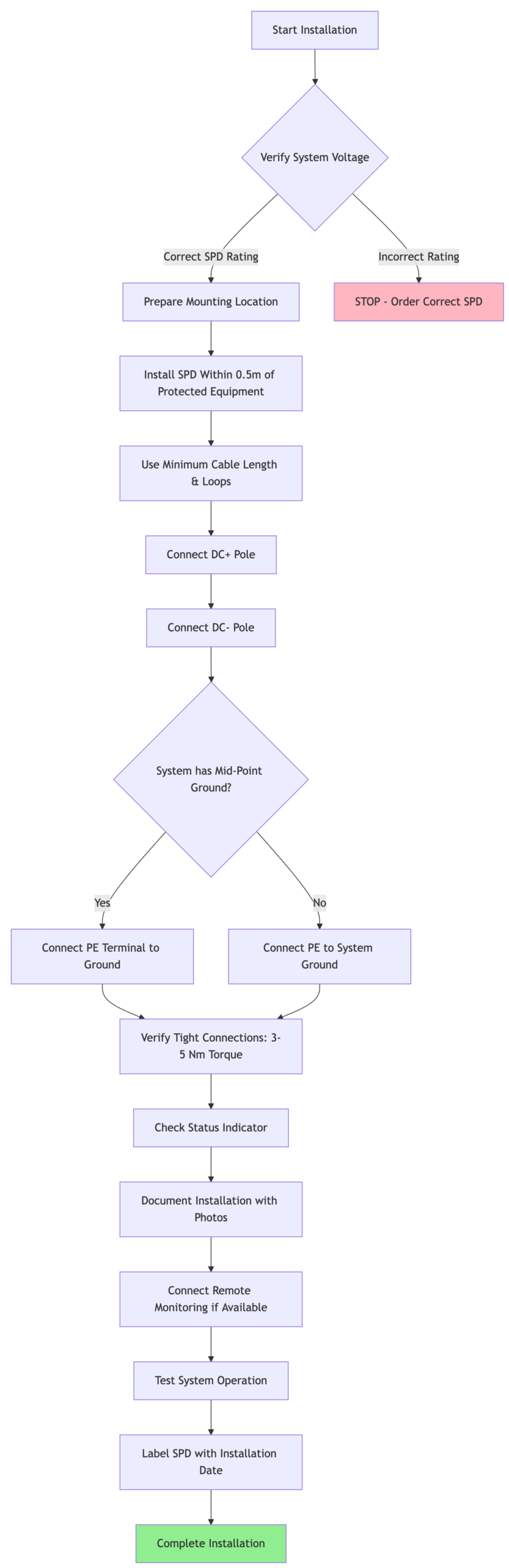
1. Cable Length and Routing (The 0.5-Meter Rule)
The connection between your SPD and the protected equipment is critical. Every meter of cable adds inductance, which creates additional voltage during fast-rising surges:
Voltage Drop Calculation:
V_additional = L × (di/dt)
Where: L ≈ 1 μH per meter of cable
       di/dt for lightning ≈ 10-100 kA/μs
مثال على ذلك: Just 2 meters of connection cable can add 200V of additional voltage rise during a surge, partially negating your SPD’s protection!
Installation Rules:
Pro-Tip: Pre-measure and cut your connection cables to exact length before installation. Mark the 0.5-meter limit on your installation template to ensure compliance during field installation.
2. Grounding Best Practices
Proper grounding is the foundation of effective surge protection:
For PV Systems with Mid-Point Grounding:
3. Physical Installation Considerations
Location and mounting affect both protection effectiveness and maintenance:
4. Connection Sequence
Always follow proper connection sequence to avoid ground faults or equipment damage:
Pro-Tip: Install a disconnect switch between your PV strings and the SPD to allow safe maintenance and replacement without de-energizing the entire array. This is especially valuable for large commercial systems where downtime is costly.
Let’s work through a complete design example to demonstrate proper pv string surge protection selection for a typical commercial installation.
Array Configuration:
الظروف البيئية:
Equipment:
Step 1: Calculate Maximum System Voltage
Voc per string (STC) = 49.5V × 20 = 990V

Temperature correction:
ΔT = 25°C - (-5°C) = 30°C
Voltage increase = 990V × (30°C × 0.0035) = 104V
Voc (cold) = 990V + 104V = 1,094V

Required Uc with 20% safety margin:
Uc(min) = 1,094V × 1.20 = 1,313V
Selection: SPDs with Uc = 1,500V DC (standard rating)
Step 2: Determine Required Voltage Protection Level
Inverter withstand voltage = 6 kV
Maximum acceptable Up = 6 kV × 0.8 = 4.8 kV
Selection: SPDs with Up ≤ 4.0 kV (providing 33% safety margin)
Step 3: Select Discharge Current Rating
For rooftop installation in moderate lightning region:
For enhanced protection (optional but recommended):
Selection: Type 2 SPD with Imax = 40 kA per pole (minimum), or Type 1+2 hybrid for critical loads
Step 4: Choose Technology
For this commercial application:
Selection: Hybrid MOV+GDT technology for optimal balance of performance and longevity
graph TB<br>النوع 2، جهد التشغيل المستمر Uc=1500 فولت<br>مستوى الحماية Up=4 كيلو فولت، أقصى تيار تفريغ Imax=40 كيلو أمبير]<br>النوع 2، جهد التشغيل المستمر Uc=1500 فولت<br>مستوى الحماية Up=3.5 كيلو فولت، أقصى تيار تفريغ Imax=60 كيلو أمبير]<br>100 كيلو واط، 1000 فولت تيار مستمر]<br>النوع 2، جهد التشغيل المستمر Uc=1500 فولت<br>مستوى الحماية Up=3.0 كيلو فولت، أقصى تيار تفريغ Imax=40 كيلو أمبير]<br>مقاومة < 5 أوم]|تأريض| GNDString-Level Protection (10 units):
Combiner Box Protection (1 unit):
Inverter Input Protection (1 unit):
Total Protection System Cost: $2,470
Key Takeaway: Compare the cost of a site-specific SPD design with the potential equipment and downtime exposure. No fixed savings or payback applies to every installation.
When evaluating whether to specify pv string surge protection, consider the true cost of going without:
| فئة التكلفة | With Proper SPD Protection | Without SPD Protection | الفرق |
|---|---|---|---|
| Initial Investment | |||
| SPD Equipment | $2,470 | $0 | +$2,470 |
| عمالة التركيب | $800 | $0 | +$800 |
| Total Initial Cost | $3,270 | $0 | +$3,270 |
| After One Surge Event | |||
| Inverter Repair/Replacement | $0 | $12,000 | -$12,000 |
| Module Replacement (4 modules) | $0 | $2,800 | -$2,800 |
| Emergency Service Call | $0 | $1,500 | -$1,500 |
| 3-Week Production Loss | $0 | $4,200 | -$4,200 |
| Inspection & Testing | $0 | $800 | -$800 |
| Monitoring System Repair | $0 | $1,200 | -$1,200 |
| Total Surge Event Cost | $0 | $22,500 | -$22,500 |
| 10-Year Lifecycle Costs | |||
| SPD Replacement (Year 6) | $1,500 | $0 | +$1,500 |
| Expected Surge Events (2-3) | $0 | $45,000-67,500 | -$45,000 |
| Warranty Coverage | Maintained | Potentially voided | Risk value: -$35,000 |
| Insurance Premium Impact | قياسي | Potentially higher | -$2,000 |
| Total 10-Year Cost | $4,770 | $82,000-104,500 | -$77,230 |
Break-Even Calculation:
Initial SPD Investment: $3,270
Average Surge Damage Cost: $22,500
Break-even point: 0.145 surge events

If your region experiences just 1 significant surge event every 7 years,
the SPD system pays for itself.

According to IEEE data, most commercial solar installations experience
2-4 damaging surge events over a 25-year lifespan without protection.
Expected ROI Over 25 Years:
Pro-Tip: When presenting surge protection to budget-conscious clients, frame it this way: ‘We can either invest $3,000 today for protection, or budget $20,000-50,000 for repairs later. The protection system is not an expense—it’s damage insurance with a 1000% ROI.’
Warranty Coverage:
Most major manufacturers include surge protection requirements in their warranties:
Insurance Premiums:
Commercial insurance providers increasingly require documentation of surge protection:
Downtime Risk:
For critical facilities (hospitals, data centers, manufacturing) or systems under Power Purchase Agreements (PPAs):
⚡ Lightning doesn’t have to strike your array directly to cause damage. Indirect strikes up to 2km away can induce surges exceeding 6,000V on unprotected PV strings. String-level protection is your first line of defense.
💰 The cost of protection is trivial compared to damage costs. A comprehensive three-stage SPD system costs $2,000-5,000 for typical commercial installations but protects against $20,000-100,000+ in potential damage. Break-even occurs after just 0.15 surge events.
🔧 SPD selection requires four critical calculations: Maximum system voltage (Voc × temperature × safety margin), required protection level (Up < 0.8 × equipment withstand voltage), discharge current rating (based on exposure level), and technology choice (hybrid MOV+GDT for best performance).
📐 Installation quality determines protection effectiveness. Keep connection cables under 0.5 meters, use minimum 6 AWG ground conductors, avoid cable loops, and ensure all connections are torqued to specification. Poor installation can reduce protection effectiveness by 50% or more.
🎯 Coordinated cascade protection is essential. Use Type 1+2 SPDs at the array combiner, Type 2 at string level, and final Type 2 protection at the inverter input. Each stage must have progressively lower Up values and be separated by adequate cable length for proper coordination.
✅ Code compliance is mandatory, not optional. NEC Article 690.35 and IEC 61643-31 require surge protection for PV systems. Proper SPD installation is necessary for permit approval, warranty validity, and insurance coverage. Document everything with photos and commissioning reports.
🔄 Plan for SPD lifecycle maintenance. Even the best SPDs have finite lifespans (typically 5-10 years depending on surge frequency). Specify devices with visual status indicators and remote monitoring capability, and schedule annual inspections to verify continued protection.
Best practice is protection at both levels. While combiner-level protection is the minimum requirement, string-level SPDs provide the first defense against surges before they propagate through the system. For optimal protection:
String-level protection becomes especially important when strings are separated by significant distances (> 50 meters) or when array wiring is exposed. The additional cost is minimal (typically $150-200 per string) compared to the protection benefit.
Type 1 SPDs handle direct lightning strikes; Type 2 SPDs handle indirect strikes and switching surges.
Type 1 devices are tested with a 10/350 μs impulse current waveform, representing the high energy from direct strikes. They can dissipate 40-50 times more energy than Type 2 devices but are larger and more expensive. Use Type 1 SPDs when:
Type 2 devices are tested with an 8/20 μs waveform and handle indirect strikes (the most common threat). They provide better voltage clamping (lower Up) and are sufficient for most rooftop installations.
Modern hybrid “Type 1+2” devices provide both capabilities in a single unit—ideal for combiner box protection where both direct and indirect surge threats exist.
Absolutely not—AC and DC SPDs are fundamentally different and not interchangeable.
AC SPDs rely on the natural current zero-crossing that occurs 100-120 times per second in AC systems to extinguish any follow current after surge protection. DC systems have no zero-crossing, meaning:
DC SPDs must be specifically designed and rated for photovoltaic applications with:
Using AC SPDs on DC circuits is a code violation, warranty voidance, and serious safety hazard. Always specify DC-rated, PV-specific surge protection devices.
Most quality SPDs have visual status indicators—but don’t rely on visual inspection alone.
Modern pv string surge protection devices include multiple failure indication methods:
Visual Indicators:
Electrical Indicators:
Inspection Schedule:
When to Replace:
Pro-Tip: Document SPD installation dates on device labels and in maintenance logs. Set calendar reminders for preventive replacement based on manufacturer recommendations—don’t wait for failure in critical applications.
Choose SPD voltage ratings based on worst-case Voc, not nominal system voltage.
بالنسبة لـ 1000V nominal systems:
Typical maximum Voc (cold): 1,100-1,200V
Recommended SPD Uc rating: 1,500V DC
Standard protection level (Up): 3.5-4.0 kV
بالنسبة لـ 1500V nominal systems:
Typical maximum Voc (cold): 1,650-1,800V
Recommended SPD Uc rating: 2,000V DC
Standard protection level (Up): 5.0-6.0 kV
Critical calculation steps:
Example for 1500V system:
Never undersize SPD voltage ratings to save cost—undersized SPDs will degrade rapidly or fail prematurely when exposed to high Voc conditions.
Neither is universally “better”—the optimal choice depends on your specific application requirements.
Choose MOV-only SPDs when:
Choose GDT-only SPDs when:
Choose Hybrid MOV+GDT SPDs when:
The industry trend is toward hybrid designs because they combine the best characteristics of both technologies:
For professional installations where system uptime and long-term protection are priorities, specify hybrid technology—the 20-30% higher initial cost is recovered through extended lifespan and superior protection performance.
Maximum 0.5 meters (50 cm) of total cable length between SPD and protected equipment—shorter is always better.
The critical principle: Every meter of connecting cable adds inductance (approximately 1 μH/meter), which creates additional voltage rise during fast surge events:
Voltage rise calculation:
V_additional = L × (di/dt)

Example with 2 meters of cable:
L = 2 meters × 1 μH/meter = 2 μH
di/dt = 50 kA/μs (typical lightning surge rate)
V_additional = 2 μH × 50,000 A/μs = 100V per meter

Total additional voltage = 200V
This additional voltage appears at the protected equipment فوق the SPD’s voltage protection level (Up), effectively reducing protection performance.
Installation best practices:
Pro-Tip: Pre-cut SPD connection cables to exact required length before installation. Use short, direct cable runs even if it requires relocating the SPD mounting position—protection effectiveness is more important than neat cable management.
For large systems with multiple combiner boxes, place SPDs at each combiner box rather than using long runs to a central SPD location. Distributed protection is more effective than centralized protection with long cable runs.
Properly selected and installed SPDs have zero impact on system performance during normal operation.
During Normal Operation:
Leakage Current Considerations:
During Surge Events:
Potential Issues Only if Incorrectly Applied:
خلاصة القول Quality SPDs are transparent to system operation. Any performance impact from properly installed surge protection is far outweighed by the protection benefit. The only “performance issue” you’ll experience is continued operation after surge events that would have otherwise destroyed your equipment.
Final Thought: In the photovoltaic industry, we often hear “every dollar saved in installation costs is profit.” But skipping pv string surge protection to save $2,000-3,000 upfront is like canceling your car insurance to save on premiums—it works great until you need it. The question isn’t whether you can afford surge protection; it’s whether you can afford to replace an entire inverter, dozens of modules, and absorb weeks of downtime when lightning strikes. Make surge protection a non-negotiable part of every PV system design—your clients (and your reputation) will thank you.