Промышленная зона Вэньян Юэцин Вэньчжоу 325000
Рабочие часы
Понедельник - пятница: 7AM - 7PM
Выходные: 10AM - 5PM
Промышленная зона Вэньян Юэцин Вэньчжоу 325000
Рабочие часы
Понедельник - пятница: 7AM - 7PM
Выходные: 10AM - 5PM

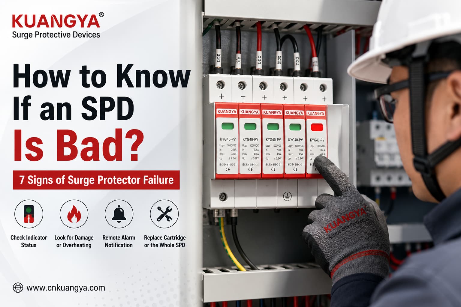
Хотите узнать, как определить неисправность УЗИП? Индикатор состояния обычно является первым элементом для проверки, однако он не дает полной информации о техническом состоянии устройства защиты от перенапряжений.
Устройство защиты от перенапряжений (УЗИП) может выглядеть абсолютно исправным снаружи даже после того, как часть его защитных функций была утрачена.
Это создает распространенную проблему для монтажников и владельцев систем:
Как понять, что УЗИП вышло из строя?
Самый быстрый способ — начать с индикатора состояния. На многих модульных УЗИП нормальный зеленый индикатор означает, что контролируемый защитный модуль находится в рабочем состоянии, тогда как красный индикатор или сигнал неисправности означают, что соответствующий модуль необходимо проверить или заменить.
Однако индикатор — это лишь часть диагностики.
УЗИП также может потребовать внимания из-за перегрева, видимых повреждений, сигнала дистанционной аварийной сигнализации, срабатывания резервного защитного устройства или воздействия аномально сильного электрического разряда.
И что важно:
Зеленый индикатор не гарантирует, что вся система защиты от перенапряжений находится в идеальном состоянии.
Правильный способ оценки состояния УЗИП заключается в сочетании показаний индикатора устройства, визуального осмотра, условий установки, истории событий и инструкций производителя.
УЗИП может быть неисправно, если индикатор состояния показывает ошибку, один или несколько модулей стали красными, на корпусе видны следы горения или деформации, устройство перегревается, срабатывает дистанционная сигнализация или УЗИП подверглось аномальному электрическому воздействию. Всегда уточняйте значение индикации в инструкциях производителя.
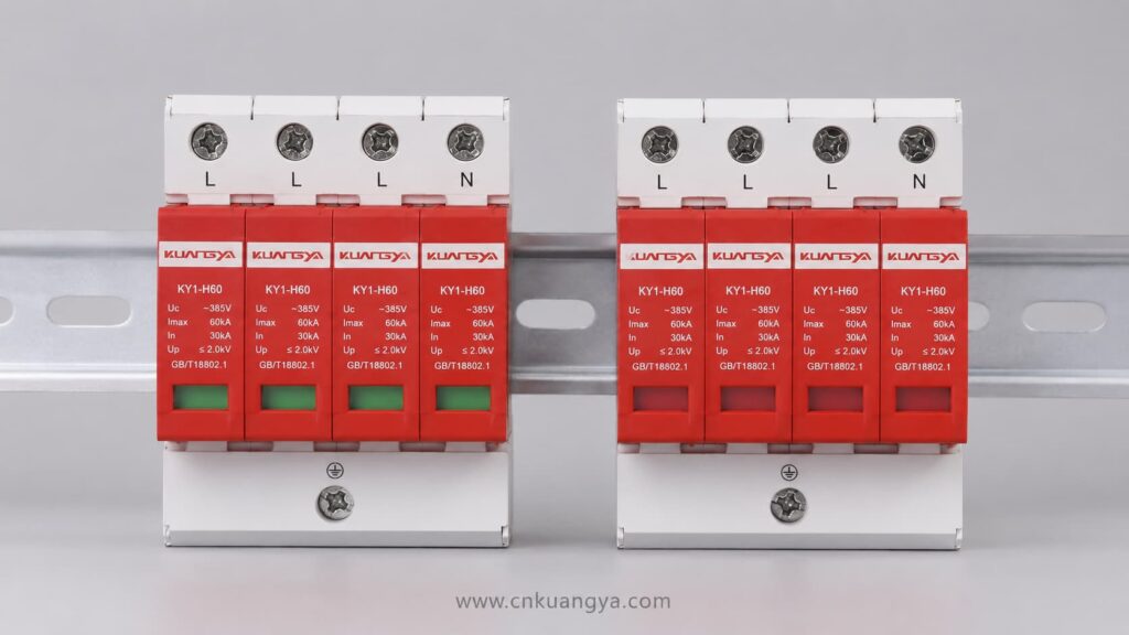
В данном руководстве объясняются 7 практических признаков неисправности УЗИП, что означает каждый из этих признаков и когда следует заменить модуль или УЗИП целиком.
УЗИП предназначено для ограничения переходных перенапряжений и отвода импульсного тока от чувствительного электрооборудования.
Современные низковольтные УЗИП обычно содержат один или несколько нелинейных защитных компонентов. Варисторы на основе оксида металла (MOV) широко используются во многих конструкциях УЗИП типа 2 и комбинированных типах.
Стандарты МЭК определяют УЗИП как устройства, содержащие по крайней мере один нелинейный компонент, который ограничивает импульсное напряжение и отводит импульсный ток. Действующие требования МЭК различают применение в цепях переменного тока, общего постоянного тока и фотоэлектрических системах постоянного тока.
При нормальном напряжении в системе элемент защиты от перенапряжений остается практически непроводящим.
При возникновении переходного перенапряжения УЗИП обеспечивает путь с низким импедансом для импульсного тока и помогает ограничить напряжение, воздействующее на подключенное оборудование.
Однако этот процесс создает электрическую и тепловую нагрузку.
После повторяющихся импульсных воздействий, сильного скачка напряжения, аномального напряжения в системе или других неблагоприятных условий защитный компонент может выйти из строя.
Поэтому многие модульные УЗИП на основе варисторов включают в себя тепловой расцепитель.
Если защитный компонент достигает небезопасного состояния, расцепитель может отсоединить его от цепи. Во многих изделиях это состояние механически связано с индикатором состояния красного/зеленого цвета.
Например, в документации Phoenix Contact представлены штекеры защиты от перенапряжений, объединяющие варистор, устройство теплового расцепления и локальный зелено-красный индикатор состояния.
Например, Phoenix Contact документирует вставные варисторные модули, включающие устройство теплового расцепления и локальную зелено-красную индикацию.
Это помогает УЗИП выйти из строя более безопасным способом.
Однако после отключения поврежденной цепи защиты система может больше не обеспечивать требуемый уровень защиты от перенапряжений.
Обычно это первое, что необходимо проверить.
Многие вставные устройства защиты от перенапряжений (УЗИП) имеют небольшое механическое окно индикации состояния на передней панели.
В зависимости от изделия нормальное состояние может отображаться как:
Состояние неисправности или необходимости замены может отображаться как:
Для многих модульных изделий на основе варисторов (MOV):
Зеленый → контролируемый защитный модуль остается работоспособным
Красный → произошло внутреннее отключение, и неисправный модуль, как правило, требует замены
Однако это не является универсальным цветовым правилом для всех УЗИП.
Разные производители используют разные индикаторы. В некоторых УЗИП вместо механических окошек используются светодиоды. В других применяются дисплеи, сигнальные контакты, символы, звуковые сигналы или комбинации этих функций.
Например, компания Schneider Electric документирует семейства УЗИП, в которых состояние светодиодов указывает на то, сохраняется ли защита от перенапряжения на каждой фазе.
Поэтому всегда проверяйте маркировку и инструкции для конкретной модели УЗИП.
Обычно нет.
Многие УЗИП для установки в распределительные щиты подключаются параллельно параллельно силовой цепи.
Таким образом, электрическая нагрузка обычно не зависит от тока, проходящего через УЗИП.
Если внутренний разъединитель УЗИП срабатывает, защищаемое оборудование может продолжать работать в штатном режиме, в то время как защита от перенапряжения на этой линии будет утрачена.
Именно поэтому неисправный УЗИП может легко остаться незамеченным.
Освещение продолжает работать.
Инвертор продолжает функционировать.
Оборудование продолжает работать.
Однако следующий импульс перенапряжения может быть ограничен уже не так эффективно.
Многополюсный УЗИП нельзя оценивать, глядя только на один картридж.
Например, при установке многомодульного устройства можно увидеть следующее:
| Состояние модуля | Возможные причины | Рекомендуемое действие |
|---|---|---|
| Все модули в норме | Локальный мониторинг не выявил неисправностей | Продолжить плановую проверку |
| Один модуль неисправен | Один из каналов защиты может быть недоступен | Провести диагностику и замену согласно спецификации |
| Неисправность нескольких модулей | Возможно значительное ухудшение характеристик УЗИП или возникновение аварийного события | Провести осмотр УЗИП в сборе и правильность его установки |
| Индикация неясна | Состояние не может быть определено с уверенностью | Ознакомьтесь с техническим паспортом или инструкциями производителя |
Предположим, что трехфазное УЗИП имеет три или четыре сменных модуля.
Если три модуля остаются зелеными, а один перешел в состояние неисправности, указанное производителем, вам следует не описывать устройство защиты от импульсных перенапряжений (УЗИП) как полностью работоспособное.
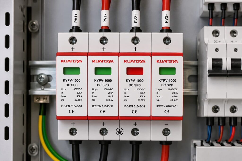
At least one intended protection path is no longer confirmed.
Not automatically.
Some modular SPDs are specifically designed so individual cartridges can be replaced.
If:
then replacing the affected cartridge may be sufficient.
However, if there is:
the complete SPD and surrounding installation should be investigated.
The status indicator is not the only thing that matters.
Always inspect the physical condition of the SPD.
Warning signs include:
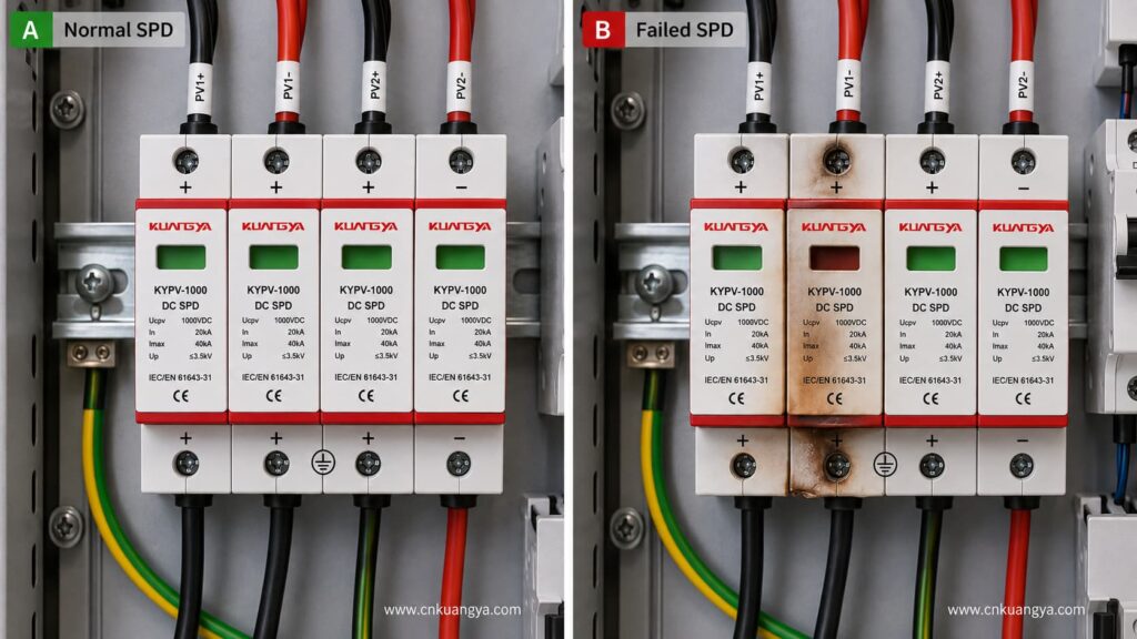
An SPD showing obvious thermal or mechanical damage should not simply be left in service because its indicator still appears green.
Physical damage can be caused by several different conditions, including:
The cause therefore matters.
Simply changing the cartridge without understanding why it was damaged can allow the same problem to happen again.
There is an important difference between:
A clean module that has reached its manufacturer-defined replacement condition
и
An SPD showing burning, melting, arcing, or mechanical damage.
In the second situation, inspection should extend beyond the replaceable cartridge.
Check the:
Severe physical damage is a reason to investigate the entire installation rather than simply installing a new plug.
Electrical equipment naturally operates at different temperatures.
But an SPD that becomes unusually hot, produces a burnt smell, or shows progressive discoloration deserves immediate attention.
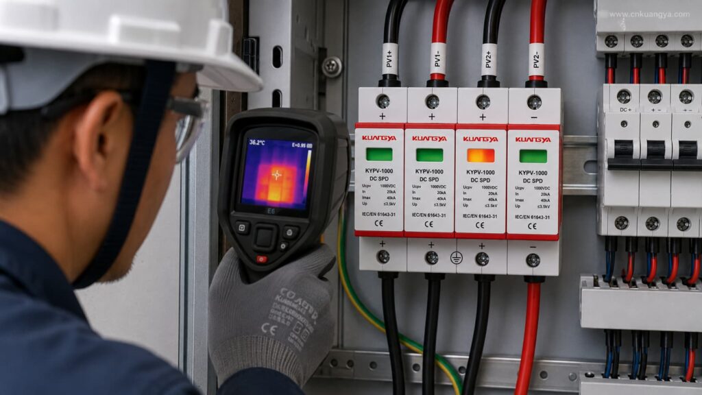
MOV-based protective components can experience increasing leakage and thermal stress as they degrade.
Proper SPD designs therefore use internal disconnecting or protective mechanisms to reduce the risk of an unsafe end-of-life condition.
Do not diagnose an energized SPD by repeatedly touching it.
If abnormal heating is suspected, inspection should be carried out by qualified personnel using appropriate procedures and instruments.
Возможные причины::
A hot SPD does not automatically prove that the MOV itself has failed.
For example, a poorly tightened terminal can create local resistance and heating even if the surge component has not reached its end of life.
That is why the location of the heat and the overall installation condition should be investigated.
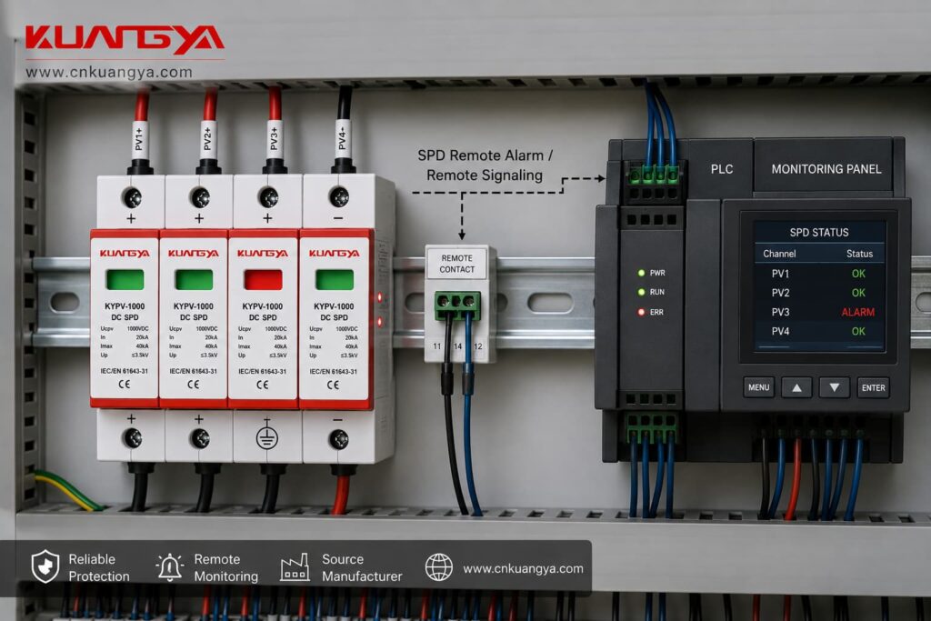
Industrial SPDs frequently offer an optional remote signaling contact.
Instead of requiring someone to open the electrical cabinet and visually check the SPD, the remote contact can communicate the SPD’s model-defined condition to equipment such as:
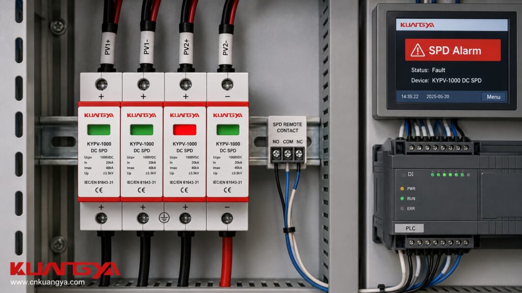
Phoenix Contact, for example, offers SPD assemblies combining local green/red indication with remote signaling.
This is useful in:
Usually, it tells you that the SPD’s monitored mechanism has changed state.
It does not automatically tell you:
Remote signaling is therefore a maintenance tool, not a complete SPD diagnostic system.
If a remote alarm appears, confirm the local SPD status and inspect the device according to the manufacturer’s instructions.
SPDs can be installed with upstream or dedicated overcurrent protection depending on the SPD design and system requirements.
If the associated fuse or circuit breaker operates unexpectedly, do not immediately assume that the breaker itself is faulty.
Возможные причины могут включать:
The backup protective device and the internal SPD disconnector do different jobs.
The internal thermal disconnector may operate because a surge protection element has reached an unsafe thermal condition without necessarily creating the type of sustained overcurrent required to trip a conventional breaker.
So this situation is possible:
SPD = failed
Breaker = still ON
This does not automatically mean the breaker has failed.
Likewise, repeatedly fitting a larger breaker is not a correct solution to repeated SPD disconnection.
The cause of the SPD failure must be investigated first.
A major lightning or switching event is an important reason to inspect an SPD.
But it is important to use careful wording here.
SPDs are specifically designed to handle transient surge currents within their declared performance capabilities.
Поэтому:
Lightning nearby ≠ SPD automatically destroyed
However, after a known severe event, especially at a critical facility, it is good maintenance practice to inspect:
If a module has entered the manufacturer’s failed state, replace it.
If there is visible damage, investigate further.
If everything remains normal, follow the manufacturer’s maintenance and post-event instructions rather than replacing the SPD without evidence.
Select the conditions you can observe and get a quick indication of whether the SPD may need further inspection or replacement.
Нет.
This is one of the most important distinctions when inspecting an SPD.
If the manufacturer defines green as the normal state, a green indicator usually means something like:
The monitored disconnect mechanism has not indicated failure and the protection module remains in its normal available state.
That is useful information.
But it is not the same as proving every aspect of SPD performance.
A green indicator normally cannot prove:
Think of the indicator as a condition signal, not a laboratory test.
If your SPD is still green, see our detailed guide to what an SPD green indicator can — and cannot — confirm about the protection system.
This is also why normal indication should be combined with periodic inspection.
Да.
This surprises many people.
A typical shunt-connected SPD is installed parallel to the circuit being protected.
A simplified arrangement looks like this:
Power Supply → Load
with the SPD connected from the live conductors toward the relevant protection path, such as PE.
The load does not normally receive its operating current through the SPD.
Therefore, when the SPD’s internal protective element is disconnected at end of life:
Load power may remain ON
while
surge protection may be reduced or lost.
This is exactly why local indicators and remote alarms are important.
Without inspection, a failed SPD can remain installed for months while everything downstream appears to operate normally.
When learning how to know if an SPD is bad, it is important to understand that a normal digital multimeter cannot fully verify surge protection performance.
Этот вопрос требует тщательного ответа.
A digital multimeter cannot reproduce the standardized surge conditions used to determine major SPD ratings.
It cannot verify:
These characteristics require controlled test equipment and defined test procedures.
IEC SPD requirements use standardized testing to establish performance and safety characteristics; ordinary low-voltage resistance measurements are not substitutes for those tests.
Depending on the SPD and the manufacturer’s instructions, a multimeter may help with:
But there is no universal resistance reading that means “SPD good.”
For MOV-based products, the small test voltage produced by a normal multimeter may be far below the voltage at which the varistor significantly conducts.
A healthy MOV can therefore appear as very high resistance or open circuit.
A degraded MOV may also appear open under the same low test voltage.
Итак:
Open circuit on a multimeter does not prove the SPD is healthy.
Likewise:
A continuity beep is not a universal SPD pass/fail test.
Dedicated SPD or MOV test equipment can provide more useful diagnostic information for some products, but results must still be compared with manufacturer-defined values for that specific SPD.
Generally, do not apply an insulation resistance tester directly across an SPD unless the manufacturer specifically provides a procedure allowing it.
Megohmmeters use test voltages much higher than an ordinary multimeter.
Because an SPD is intentionally designed to conduct when voltage rises above certain conditions, insulation testing can:
For system insulation testing, SPDs may need to be disconnected or removed according to the manufacturer’s instructions and applicable installation procedures.
Never assume an SPD should behave like ordinary insulation.
Understanding the reason is important because simply installing another SPD may not solve the underlying problem.
Every surge does not necessarily destroy an SPD.
However, repeated surge activity can progressively stress protective components.
The actual service life depends on factors such as:
There is therefore no reliable rule such as:
“An SPD always lasts exactly five years.”
Calendar age alone does not determine SPD condition.
SPDs have declared surge-current capabilities.
A sufficiently severe electrical event can exceed the capability of a particular protection system.
This is one reason correct Type selection and coordinated surge protection are important.
Type 1, Type 2, and combined Type 1+2 SPDs are not simply different quality levels.
If you are unsure which classification applies, see our guide to Type 1 vs Type 2 vs Type 1+2 SPD for a more detailed comparison.
A transient surge and a temporary overvoltage are not the same thing.
A surge is generally very short.
A temporary overvoltage, or TOV, can remain for much longer.
An SPD designed to conduct short transient energy should not be expected to clamp an abnormal power-frequency overvoltage indefinitely.
Improper TOV conditions can therefore create serious stress on an SPD.
Current IEC requirements specifically consider TOV and fault conditions as part of SPD application and testing.
Selecting an SPD with an unsuitable maximum continuous operating voltage can cause problems.
For AC systems, the relevant value is commonly expressed as Uc.
For photovoltaic applications, Ucpv is particularly important.
For photovoltaic DC applications, IEC 61643-31 specifies requirements and test methods for SPDs intended for the DC side of PV installations.
If you are not familiar with these ratings, our guide to DC SPD specifications explains Ucpv, In, Imax, Up and Iscpv separately.
If the SPD’s voltage rating is too low for the maximum voltage that can continuously appear in the system, the protection component can be stressed during normal or abnormal operating conditions.
For PV systems, remember that array voltage changes with temperature.
Maximum PV open-circuit voltage under expected low-temperature conditions therefore needs to be considered when selecting the DC SPD.
For the full selection process, see how to select the correct DC SPD voltage rating for a solar PV system.
Even a good SPD can perform poorly if it is installed incorrectly.
Important installation factors include:
Long connection leads are particularly important because the inductive voltage developed along the conductors during a rapidly changing surge current can add to the voltage seen by the protected equipment.
SPD location and lead length are two different installation issues. See why SPD distance from the inverter matters for a detailed explanation of the 10 m system-distance rule and the approximately 0.5 m connection-lead recommendation.
This means SPD performance depends not only on the number printed next to Вверх, but also on how the SPD is actually installed.
Environmental stress can also shorten SPD service life.
Примеры включают:
These conditions can affect terminals, insulation, contacts, and surrounding installation components even before the internal surge element reaches normal end of life.
A simple field inspection can follow this order.
Check:
Do not install a cartridge just because it physically fits the base.
Confirm what the indicator means for that exact product.
Do not automatically assume every green window means normal and every red window means failure without checking the manufacturer’s markings.
For multi-pole SPDs, inspect all cartridges.
One failed module can mean the complete intended protection arrangement is no longer available.
Проверьте наличие:
If remote signaling is installed, compare the remote alarm state with the local status.
A mismatch should be investigated.
Ask whether the installation recently experienced:
| Состояние | Typical Action |
|---|---|
| Manufacturer-defined normal indicator, no other problems | Continue normal monitoring |
| Failed/red module | Replace according to manufacturer instructions |
| One cartridge failed | Inspect assembly and replace affected cartridge if permitted |
| Multiple cartridges failed | Inspect complete SPD and system |
| Burnt or melted base | Investigate and normally replace complete damaged assembly |
| Remote fault alarm | Confirm local status and investigate |
| Severe event but normal indication | Inspect according to maintenance instructions |
| Repeated replacement failures | Investigate system voltage, wiring, TOV and coordination |
| Condition uncertain | Treat protection as unconfirmed until properly assessed |
Many DIN-rail SPDs are modular.
They consist of:
Base + replaceable protection cartridge
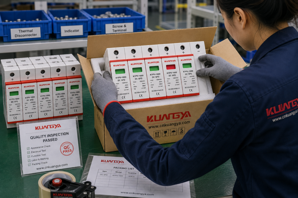
For reference, you can also view our DC surge protective device range, including modular Type 2 and Type 1+2 models with replaceable cartridges.
This allows easier maintenance.
Never bypass the SPD’s internal thermal disconnector or attempt to reset a sealed failed cartridge.
A cartridge that has entered its defined end-of-life condition is normally intended to be replaced rather than repaired.
If the manufacturer-defined indication shows that the intended surge protection path is no longer available, replacement should not be unnecessarily delayed.
The electrical system may continue running without it.
But that does not mean continued operation without surge protection is desirable.
Это особенно важно для:
The longer the failed SPD remains in place, the longer the equipment may remain exposed to the next transient event.
There is no single inspection interval suitable for every installation.
Inspection frequency should consider:
Inspection is particularly useful:
For unattended or critical installations, remote signaling can make it easier to detect a failed SPD quickly.
Seeing a failed SPD sometimes leads to the assumption:
“The SPD failed, so it must be defective.”
That conclusion is not always correct.
An SPD is a protective device exposed directly to electrical stress.
A failure indication may mean that it experienced the kind of abnormal condition its protective and disconnecting mechanisms were designed to handle safely.
The more useful question is:
Why did the SPD reach this condition?
Investigate:
If the same SPD position fails repeatedly, replacing cartridges without investigating the system is not enough.
The easiest sign of SPD failure is a manufacturer-defined failure or replacement indication, commonly red on many modular SPDs.
But that should not be the only check.
An SPD should also be investigated if you find:
At the same time, do not assume that a green indicator proves the entire surge protection system is perfect.
It usually confirms only the condition monitored by that particular SPD.
And do not rely on a normal multimeter resistance test to prove surge performance.
Correct SPD assessment combines:
product status + visual inspection + installation condition + event history + manufacturer instructions.
If a modular SPD has reached its defined end-of-life state, replace the affected cartridge or assembly as specified.
More importantly, if failure is repeated or accompanied by physical damage, investigate the underlying electrical system before simply installing another SPD.
Ultimately, how to know if an SPD is bad comes down to combining the status indication, physical inspection, event history, installation condition and manufacturer guidance rather than relying on a single test.
Start with the manufacturer’s status indicator. If the product defines the displayed condition as normal and there is no physical damage or alarm, the monitored module remains in its normal indicated state. However, the status indicator does not prove complete surge performance or remaining lifetime.
On many modular SPDs, green means that the monitored protection module has not entered its failure or disconnection state.
But always confirm the manufacturer’s markings because indicator systems vary between products.
Green should not be interpreted as proof that the complete installation is perfectly protected.
On many plug-in MOV-based SPDs, a red indicator means the protection module has reached a manufacturer-defined failed or replacement condition, often associated with an internal disconnector.
The affected cartridge normally needs to be replaced.
Check the exact product instructions before taking action.
Да.
Most panel-mounted SPDs are connected in parallel with the protected circuit.
The load can therefore remain energized even if the SPD protection element has been disconnected.
Only to a limited extent.
A multimeter may help check remote dry contacts or investigate certain basic electrical conditions when permitted by the manufacturer.
It cannot verify surge ratings such as Up, In, Imax, or Iimp, and there is no universal resistance value that proves an SPD is healthy.
Not automatically.
Inspect the SPD after a significant event and follow the manufacturer’s maintenance instructions.
Replace it if it shows a failure indication, physical damage, abnormal condition, or if the manufacturer specifically requires replacement after the event.
Replaceable cartridges are common in modular SPDs. For example, Schneider Electric explains that when the SPD end-of-life indicator turns red, the cartridge should be replaced.
Often yes, if the SPD is designed with replaceable plug-in modules and the base is undamaged.
Use only the correct compatible replacement cartridge specified for that SPD.
If the base, terminals, or surrounding components show heat or arc damage, the complete assembly should be investigated.
Repeated failure can indicate more than ordinary surge aging.
Возможные причины::
If cartridges repeatedly fail at the same location, investigate the system instead of continuing to replace modules without identifying the cause.
No reliable fixed lifetime can be determined from indicator color alone.
SPD life depends on the electrical stress it experiences, environmental conditions, product design, and installation.
The indicator should be treated as one part of a wider inspection and maintenance process.

