Промышленная зона Вэньян Юэцин Вэньчжоу 325000
Рабочие часы
Понедельник - пятница: 7AM - 7PM
Выходные: 10AM - 5PM
Промышленная зона Вэньян Юэцин Вэньчжоу 325000
Рабочие часы
Понедельник - пятница: 7AM - 7PM
Выходные: 10AM - 5PM

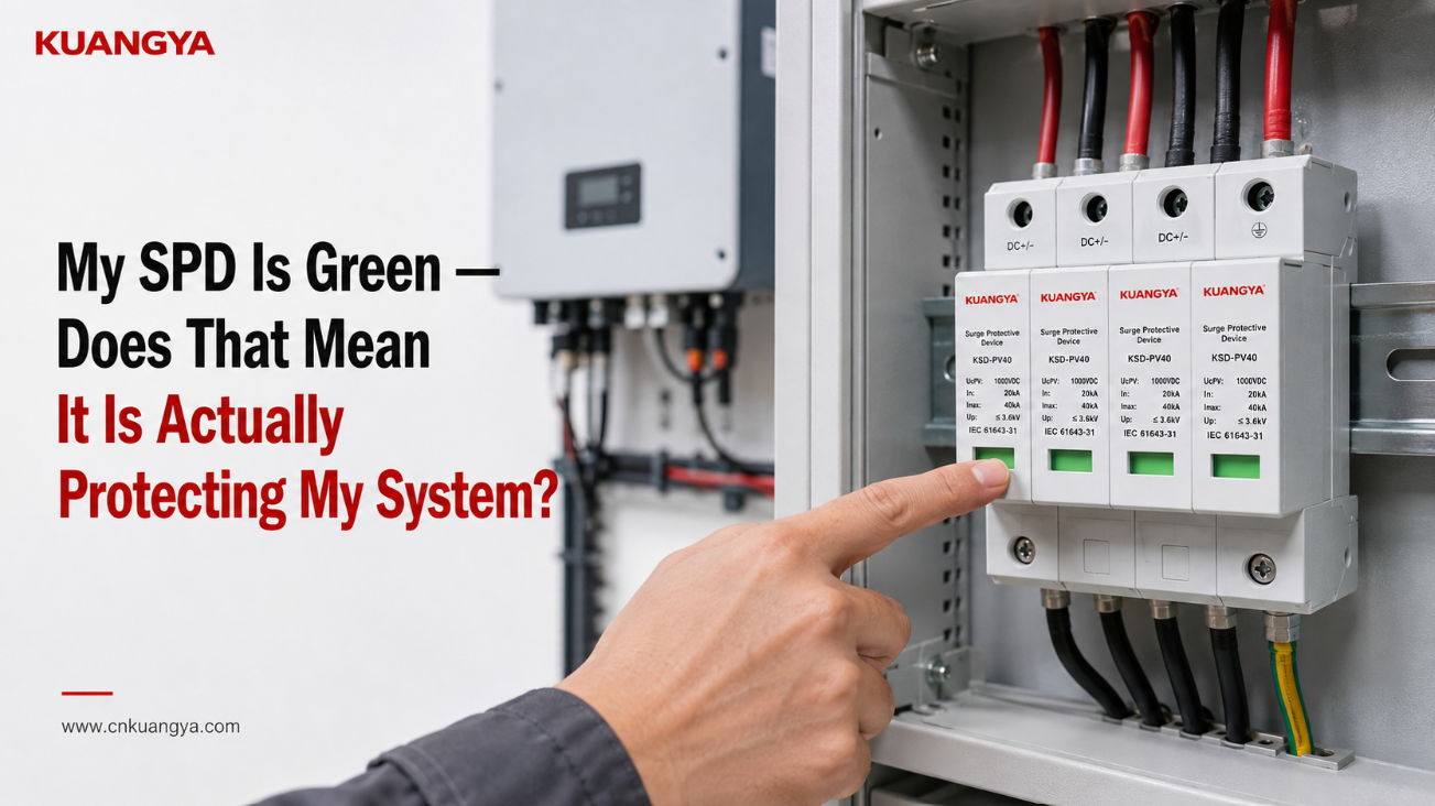
Вы открываете распределительный щит солнечной электростанции, смотрите на устройство защиты от перенапряжений (УЗИП) и видите зеленый индикатор. Зеленый индикатор УЗИП выглядит нормально, но означает ли это, что система действительно защищена?
Все выглядит нормально.
Означает ли это, что УЗИП определенно защищает инвертор и остальную часть фотоэлектрической системы?
Не обязательно.
На многих модульных устройствах защиты от перенапряжений зеленый индикатор состояния означает, что контролируемый модуль УЗИП все еще находится в нормальном или рабочем состоянии, определенном производителем. Проще говоря, устройство не сигнализирует о том, что его внутренний защитный элемент достиг состояния отказа, требующего отключения или замены.
Но этот зеленый индикатор не может подтвердить все аспекты работы системы защиты.
Он не может сказать вам, правильно ли было выбрано УЗИП, верна ли схема подключения, не слишком ли длинный путь соединения, подходит ли система заземления и уравнивания потенциалов, или какова остаточная способность поглощения импульсных перенапряжений после предыдущих воздействий.
Самый безопасный способ понять значение зеленого индикатора:
Зеленый цвет обычно означает, что УЗИП не сообщило об отказе. Это не означает, что каждый элемент системы защиты от перенапряжений был проверен.
Это различие особенно важно в фотоэлектрических системах, где напряжение постоянного тока, конфигурация УЗИП, прокладка кабелей, расположение инвертора, система заземления и метод монтажа влияют на реальную эффективность защиты от перенапряжений.
Для УЗИП, у которого производитель определяет зеленый цвет как нормальный:
| Что вы видите | Что это обычно означает | Что это НЕ доказывает |
|---|---|---|
| Зеленый индикатор | Контролируемый модуль УЗИП не сигнализирует о достижении состояния отказа/окончания срока службы | Правильный монтаж |
| Все модули зеленые | Все видимые контролируемые модули сообщают о своем нормальном состоянии | Правильный выбор УЗИП |
| Инвертор работает в штатном режиме | Преобразование энергии осуществляется | УЗИП обеспечивает эффективную защиту от перенапряжений |
| Зеленый индикатор после грозы | Контролируемый разъединитель не сообщал об отказе | Скачков напряжения не зафиксировано |
| Зеленый индикатор после многих лет эксплуатации | Контролируемый модуль не сообщал об отказе | Полная исходная импульсная пропускная способность сохраняется |
| Зеленое окно + отсутствие сигнала тревоги | В настоящее время контролируемых отказов не зафиксировано | Правильное заземление, соединение, монтаж или координация |
Точное значение всегда должно быть подтверждено в техническом паспорте или инструкции по установке для конкретного УЗИП.
Это важно, потому что зеленый и красный являются распространенными цветами индикации, но они не являются универсальным диагностическим языком для всех УЗИП, представленных на рынке.
Некоторые УЗИП используют механическое цветное окно. Другие используют светодиоды, символы, дистанционные контакты, звуковые сигналы или электронный мониторинг.
Например, некоторые коммерческие УЗИП используют локальную зеленую/красную индикацию состояния вместе с дистанционной сигнализацией.
Поэтому перед интерпретацией цвета сначала уточните, что именно он означает согласно документации производителя.
Многие современные модульные УЗИП содержат защитный элемент, такой как металлооксидный варистор (MOV), вместе с механизмом отключения.
Во время нормальной работы УЗИП на основе варистора находится в высокоомном состоянии.
При возникновении переходного перенапряжения защитный элемент становится проводящим и отводит импульсный ток через предусмотренный путь защиты, помогая ограничить напряжение, поступающее на чувствительное оборудование.
Со временем повторяющиеся электрические нагрузки, аномальное перенапряжение или достаточно серьезное событие могут привести к деградации защитного элемента.
Многие конструкции УЗИП включают внутренний механизм отключения для изоляции защитного элемента, который достиг определенного небезопасного или неисправного состояния.
Визуальный индикатор состояния часто механически или электрически связан с этой системой мониторинга или отключения.
Для данного типа УЗИП:
Зеленый цвет может указывать на то, что:
Контролируемый защитный модуль подключен и не достиг состояния неисправности, определенного производителем.
Красный цвет может указывать на то, что:
Контролируемый защитный элемент был отключен или модуль достиг состояния, требующего замены.
Однако точный принцип работы зависит от конструкции УЗИП.
Вот почему лучше сказать:
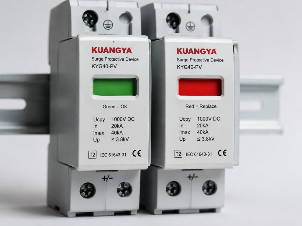
Зеленый = модуль в данный момент сообщает о своем нормальном состоянии.
вместо:
Зеленый = вся электрическая система гарантированно защищена.
Это звучит как незначительная деталь, но она вызывает ненужную путаницу.
Многие УЗИП на DIN-рейку на самом деле не содержат зеленого светодиода.
Зеленый прямоугольник, видимый на передней панели картриджа, может быть просто механическим индикатором состояния.
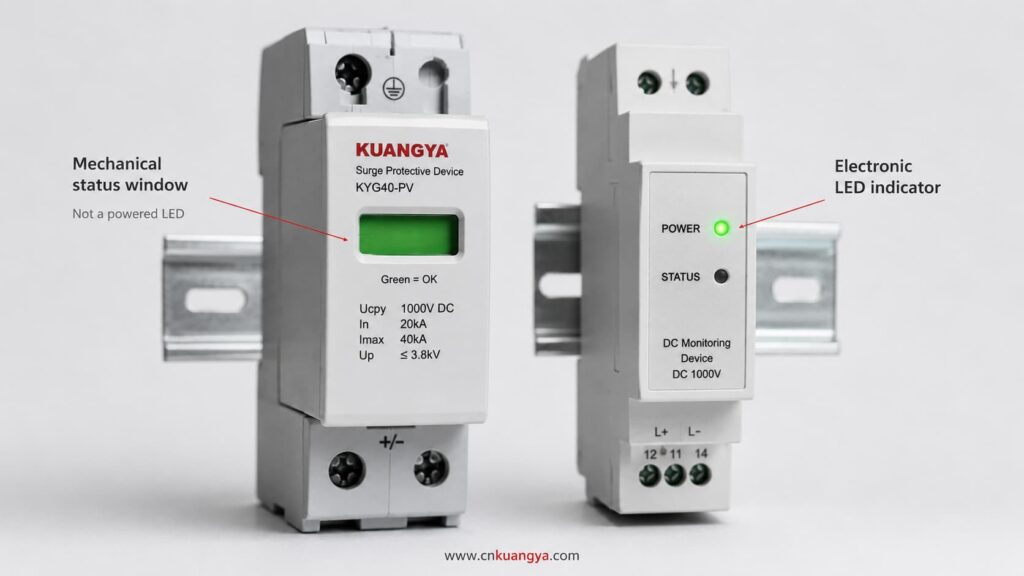
Например, механизм внутри УЗИП может перемещать цветной флажок при срабатывании внутреннего разъединителя.
Это означает, что индикатор может оставаться видимым даже при обесточенной электрической системе.
Поэтому такие утверждения, как:
“Зеленый индикатор горит, значит, на УЗИП подано питание”,”
могут быть неверными.
Механическое индикаторное окно зеленого цвета может указывать на физическое состояние модуля УЗИП, а не на наличие напряжения питания.
Всегда определяйте, использует ли изделие:
В документации к изделию это должно быть четко указано.
Это один из самых важных моментов, который необходимо понимать.
В большинстве типичных систем электроснабжения УЗИП подключается параллельно защищаемой цепи.
Он обычно не проводит рабочий ток инвертора.
При нормальных значениях напряжения УЗИП остается практически неактивным.
При возникновении переходного перенапряжения он обеспечивает путь для импульсного тока и ограничивает напряжение в соответствии со своей конструкцией.
Благодаря такому параллельному подключению модуль защиты УЗИП может быть отключен, в то время как основная цепь продолжает функционировать.
Результат может быть следующим:
Инвертор: работает в штатном режиме
Выработка электроэнергии ФЭМ: в норме
Модуль УЗИП: неисправен или отключен
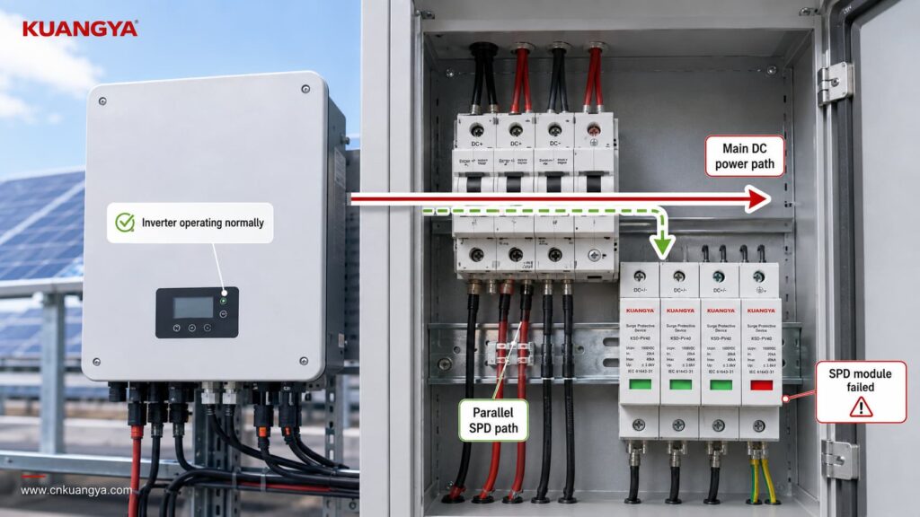
Именно поэтому проверка только работоспособности инвертора не дает информации о том, активна ли защита от перенапряжений.
Фотоэлектрическая система может продолжать вырабатывать электроэнергию даже после выхода из строя одного из путей защиты от перенапряжений.
Именно поэтому индикатор состояния имеет значение.
Но верно и обратное:
A green indicator does not prove that the complete surge protection arrangement is correct.
Think of the indicator as answering one narrow question:
Has the monitored SPD module entered the failure state that this indicator is designed to detect?
It is not answering every engineering question about the installation.
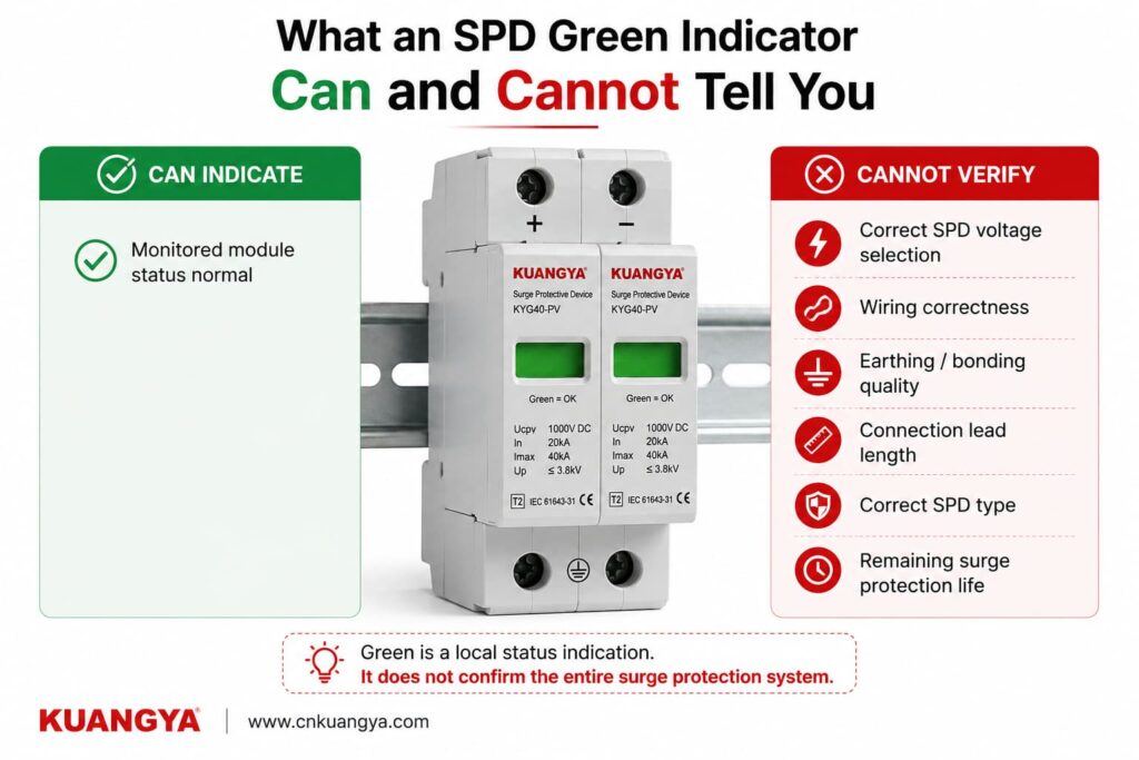
The module has not reached its manufacturer-defined indicated failure state.
The internal disconnection/status mechanism has not reported the condition associated with replacement.
The module is not currently displaying its normal visual failure warning.
Whether the SPD voltage rating is suitable for the PV array.
Whether the SPD is intended for AC or DC operation.
Whether the correct Type 1, Type 2 or combined Type 1+2 protection has been selected.
Whether the voltage protection level is suitable for the equipment being protected.
Whether the SPD is wired according to the correct PV configuration.
Whether all protection modes are connected correctly.
Whether the earthing and equipotential bonding arrangement is correct.
Whether the SPD connection conductors are unnecessarily long.
Whether the required backup overcurrent protection is correct.
Whether a previous surge has reduced the remaining capability of the protection element.
Whether a surge event has occurred.
Whether the SPD would perform exactly as declared during the next transient event.
That is why a green indicator should be treated as one inspection point, not as a complete SPD test.
If the SPD is green, the next question should not be:
“Is everything perfect?”
Более правильный вопрос:
“Does the rest of the installation support the protection that this SPD is designed to provide?”
Here are the most important checks.
Never assume the color meaning only from experience with another brand.
Check the:
For many modular SPDs, green means normal and red means replacement or fault.
But that interpretation should still come from the documentation of the exact product.
This becomes particularly important with multi-function products that may have separate indicators for:
A green indicator is only useful if you know exactly what it is indicating.
A multi-pole SPD can contain several protection modules or protection paths.
For example, a PV SPD assembly may have several cartridges depending on the system topology and protection arrangement.
If three windows are green but one is red, you should not describe the SPD as:
“Basically OK.”
One failed protection path may mean the complete intended protection arrangement is no longer available.
Check every visible status indicator.
For plug-in designs, also make sure the required cartridges are present and correctly installed according to the manufacturer’s instructions.
If one module shows the manufacturer’s defined failure condition, follow the manufacturer’s replacement procedure and investigate whether any additional inspection is required.
A perfectly green SPD can still be the wrong SPD.
This is one of the biggest reasons that green does not equal correctly protected.
For a solar PV installation, check whether the SPD is specifically suitable for the DC side of a photovoltaic system.
IEC 61643-31 addresses SPDs intended for the DC side of PV installations up to 1500 V DC.
The SPD should therefore be selected according to the actual system rather than simply according to appearance or nominal voltage.
Important parameters may include:
System application
AC SPD and PV DC SPD are not automatically interchangeable.
Максимальное длительное рабочее напряжение
For PV SPDs, the selected continuous voltage rating must be suitable for the maximum voltage that can occur in the PV circuit under the applicable design conditions.
Voltage protection level — Up
A lower Up generally means a lower declared residual voltage during the specified test conditions, but it must be considered together with system voltage, SPD type and coordination.
Discharge current ratings
Depending on the SPD classification, datasheets may specify values such as In, Imax or Iimp.
Тип СПД
If these markings are unfamiliar, see our guide to DC SPD specifications such as Ucpv, In, Imax, Up and Iscpv.
Whether Type 1, Type 2 or a combined Type 1+2 SPD is appropriate depends on the installation, lightning exposure, lightning protection concept and applicable standards.
A green Type 2 SPD cannot turn itself into a Type 1 SPD simply because the indicator looks normal.
Correct application still matters.
An SPD only works through the electrical paths actually connected to it.
A green indicator cannot detect every wiring error.
In a PV installation, the SPD connection must match the system architecture and the manufacturer’s wiring diagram.
Do not assume that every DC SPD is wired identically.
Different products and PV system configurations can use different protection arrangements.
Incorrect connections can result in a situation where:
The SPD itself appears normal, but the surge protection path is not the path the system actually needs.
Polarity, protection modes, terminal identification and connection to PE or the relevant equipotential bonding system must follow the device instructions and system design.
The front indicator usually does not verify all of these installation details.
Even when an SPD is correctly selected and still green, installation geometry matters.
During a surge, current changes extremely quickly.
The inductance of the connecting conductors can therefore create additional voltage.
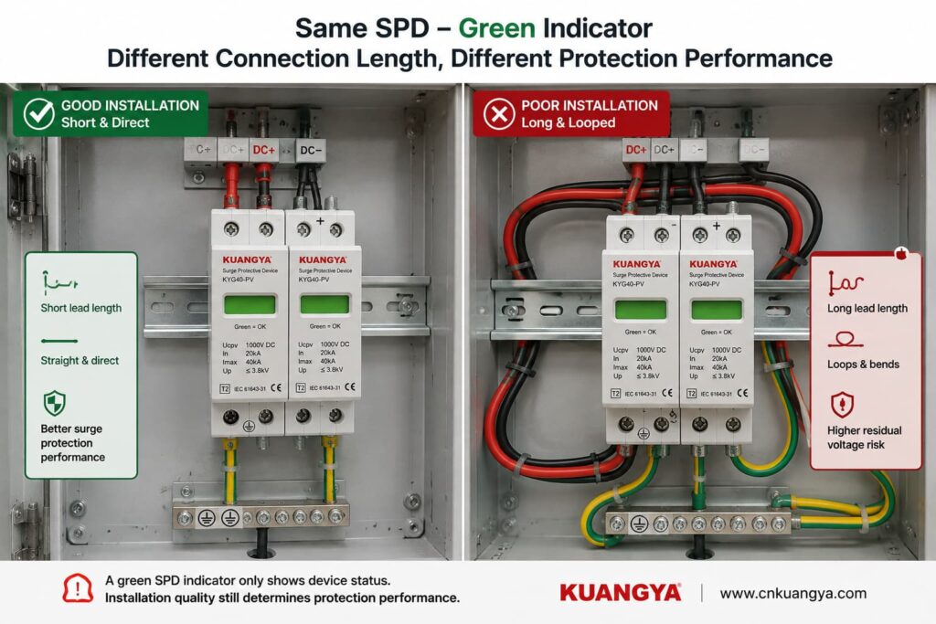
Long, looping or poorly routed SPD conductors can increase the voltage appearing at the protected equipment during a transient.
This means two identical green SPDs can provide different real installation performance if one has short, direct connections and the other is connected using unnecessarily long conductors.
This is why SPD installation instructions commonly emphasize short and direct connections.
Итак:
Green tells you about the monitored SPD module. It does not tell you whether the wiring around the SPD is optimized for surge performance.
If you want to understand this issue in more detail, see our guide:
Имеет ли значение расстояние между УЗИП и инвертором?
An SPD does not work in isolation.
The complete surge-current path matters.
Depending on the system topology and SPD design, this can involve PE conductors, bonding conductors, equipotential bonding and the installation’s earthing arrangement.
A green SPD indicator usually does not verify the quality of those external connections.
Possible installation problems can include:
loose connections,
corroded connections,
incorrect bonding,
poor conductor routing,
connection to the wrong reference point,
or an installation arrangement that does not match the SPD wiring diagram.
For solar PV systems, the correct earthing and bonding arrangement depends on the system design and applicable installation requirements.
Therefore, avoid the overly simple statement:
“An SPD just sends everything into the ground.”
The real current paths depend on SPD topology and system configuration.
What matters is that the SPD is installed according to its declared protection modes and the applicable electrical design.
Depending on the product and installation, the SPD manufacturer may specify backup overcurrent protection or coordination requirements.
A green window does not confirm that the required upstream protective device has been selected correctly.
Check the exact product instructions.
Also inspect the SPD externally where this can be done safely.
Warning signs include:
Visible damage should not be ignored simply because the status window still appears green.
Where inspection requires opening energized equipment or accessing hazardous terminals, the work should be performed by qualified personnel following appropriate electrical safety procedures.
An SPD green indicator is useful, but it is only one part of the picture.
Use the checker below as a basic installation review, not as an electrical test or certification of the SPD.
Answer these quick questions to review the basic condition of your SPD installation.
Does the manufacturer documentation confirm that green means normal / available for this SPD?
Are all required SPD modules showing their normal status?
Is the SPD suitable for the actual application and system voltage, such as PV DC use where applicable?
Has the SPD wiring been checked against the manufacturer’s connection diagram?
Are the SPD connection conductors kept short and direct according to the installation instructions?
Has the required earthing / bonding arrangement been checked?
Is the SPD free from visible signs of burning, cracking, deformation or overheating?
The result should be treated as an inspection prompt.
It cannot reproduce an IEC surge test, measure remaining MOV life or guarantee protection against a future lightning event.
This is another very common misunderstanding.
Imagine that a thunderstorm passes near the PV installation.
The inverter continues operating.
You inspect the SPD.
It is still green.
Does this mean the surge never reached the system?
Нет.
A surge can occur without forcing the SPD into its failure state.
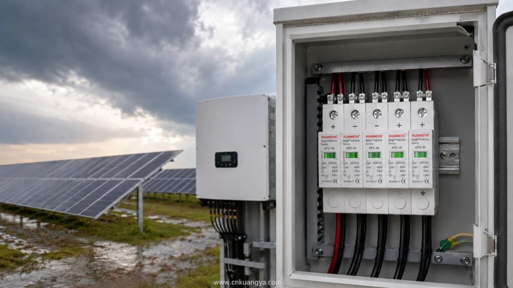
That is the purpose of an SPD: it is designed to withstand and handle transient events within its declared capabilities.
So an SPD may experience a surge, perform its protective function and remain in its normal indicated state afterward.
The green indicator is not normally an event counter.
It does not necessarily tell you:
Some more advanced monitoring systems can record surge events or estimate device condition.
A basic green/red status window usually cannot.
Поэтому:
Green after a storm does not prove that nothing happened. It only tells you that the SPD has not entered the failure state represented by that indicator.
For important or critical systems, follow the manufacturer’s inspection recommendations after significant electrical or lightning events.
Potentially, yes.
This is one of the reasons not to describe the green window as a complete health measurement.
MOV-based surge protective elements can experience cumulative electrical stress.
The amount of degradation depends on factors such as:
However, this does не mean that you can calculate SPD life simply by counting thunderstorms.
There is no reliable universal rule such as:
“An SPD survives exactly 20 surges.”
или:
“Replace every SPD after three years.”
Surge exposure is not identical from event to event.
A large event and a small transient do not impose the same electrical stress.
The green/red mechanism is usually a threshold-type status indication, not a precise remaining-life meter.
More sophisticated monitoring systems can provide additional condition information, but a basic mechanical indicator normally cannot show a percentage such as:
SPD life remaining: 63%.
So avoid any tool or article claiming to calculate exact SPD remaining life from only age, number of storms or visual indicator color.
Нет.
It is better to say that the monitored SPD has not reached the condition that causes its status mechanism to indicate failure.
That is different from saying the protection element is identical to a brand-new component.
The SPD may have experienced previous stress without reaching its disconnection threshold.
For normal installations, this does not automatically mean the SPD must be replaced.
The important point is simply that the green indicator is not a laboratory measurement of every electrical characteristic inside the SPD.
A normal multimeter can be useful for certain electrical checks, but it cannot fully verify surge-protection performance.
A standardized SPD test involves transient conditions that an ordinary handheld multimeter does not reproduce.
For example, a multimeter does not apply standardized surge-current waveforms to determine parameters such as the SPD’s declared voltage protection level or impulse-current performance.
For many MOV-based SPDs, measuring resistance at the low voltage produced by a multimeter may simply show a very high resistance or open-circuit-like reading.
That alone does not prove the SPD will perform correctly during a surge.
Similarly:
Continuity = good SPD
is not a universal test rule.
For products with a remote signaling contact, a meter may sometimes be used to check that contact when the manufacturer permits it and the circuit is safely isolated.
But the remote contact still only reports the status designed into the device.
It does not perform a full surge test.
For installed SPDs, follow the manufacturer’s inspection and testing procedure.
Some SPDs include a dry contact or changeover contact for remote status monitoring.
This is useful in:
The remote contact can be connected to monitoring equipment such as a PLC, BMS, inverter monitoring system or SCADA system.
If the SPD changes to its defined fault condition, the remote contact can trigger an alarm.
This solves an important practical problem:
Without remote monitoring, a failed SPD may remain unnoticed inside a cabinet for a long time.
However, remote signaling has the same fundamental limitation as the local indicator.
It can report the condition the SPD is designed to monitor.
It normally does not automatically tell you:
So remote monitoring improves visibility, but it does not replace correct engineering.
A green SPD deserves further inspection when something else about the installation creates doubt.
Примеры включают:
Follow the equipment manufacturer’s post-event inspection instructions.
A previously correct SPD can become poorly coordinated after changes to the PV array, inverter, distribution board, cabling or protection scheme.
Check the product data rather than relying on the green indicator.
Review SPD placement and connection length.
Do not let a green window override obvious physical warning signs.
Repeated SPD failure may indicate a system problem such as incorrect voltage selection, temporary overvoltage, wiring problems or abnormal electrical stress.
Simply installing another identical cartridge repeatedly is not a root-cause solution.
The clearest replacement condition is when the manufacturer-defined status indicator shows that the module has failed or reached end of life.
For many replaceable modular SPDs, this is shown by a red status window.
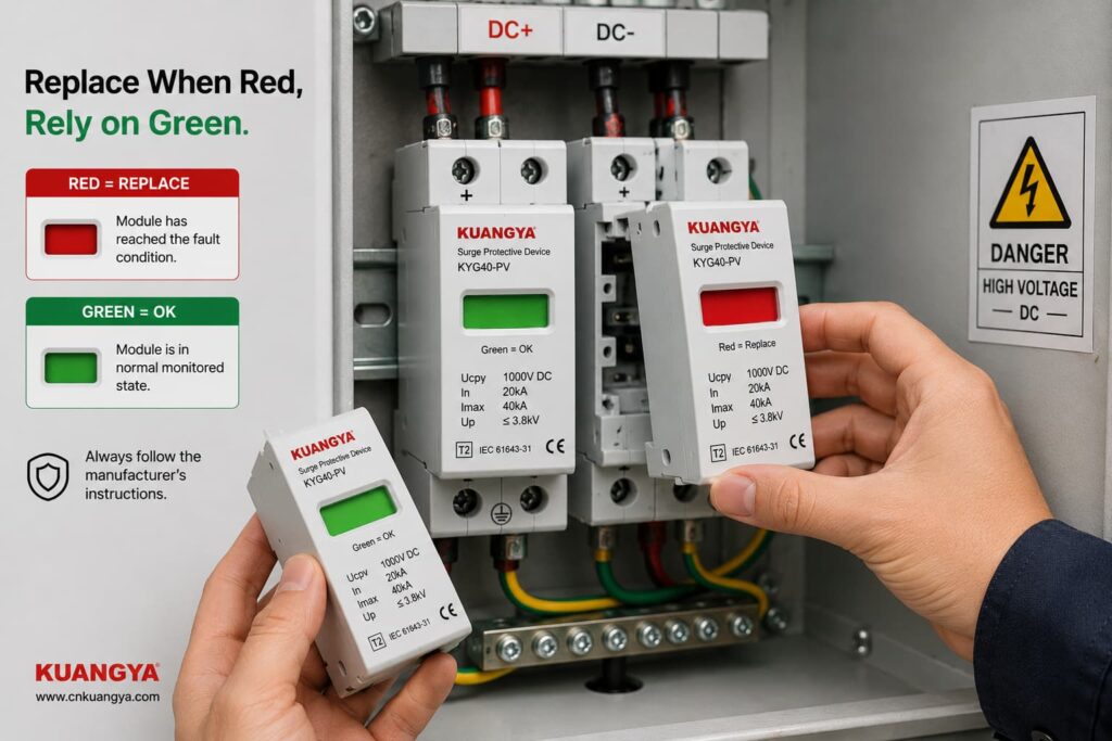
For solar PV applications, you can also view our DC surge protective device range for PV systems, including Type 2 and Type 1+2 models with replaceable modules and visual status indication.
Follow the exact manufacturer’s instructions regarding whether to replace:
Replacement may also be required when there is physical damage or when the manufacturer’s inspection procedure identifies another reason to remove the device from service.
Do not bypass an internal disconnector or attempt to repair a sealed SPD protection cartridge unless the manufacturer specifically provides an approved service procedure.
Consider a 1000 V-class solar PV system with a DC SPD installed close to the inverter.
The SPD windows are all green.
What can we conclude?
We can reasonably say:
The visible monitored SPD modules currently report their normal state, assuming the product documentation defines green as normal.
But before saying:
“The inverter is fully protected.”
we would still want to know:
Is the SPD specifically rated for PV DC use?
Is its maximum continuous operating voltage suitable for the PV array’s maximum design voltage?
Is the correct SPD Type installed for the lightning protection concept?
Does the wiring follow the manufacturer’s PV connection diagram?
Are all protection modes connected?
Are the conductors short and direct?
Is the earthing/bonding arrangement correct?
Is required backup protection installed?
Are all cartridges seated and undamaged?
Only after those questions have been considered does the green indicator become part of a more complete protection assessment.
Suppose a PV array has an SPD in the combiner box.
It is green.
The inverter is located a considerable cable distance away.
Can we simply say:
“There is already a green SPD, so the inverter is protected.”
Not automatically.
The question is no longer only about SPD condition.
It also becomes a question of SPD placement, cable length, protection coordination and whether additional protection is required near the equipment.
This is why SPD status and SPD system design should be treated as two different questions:
Question 1: Is the installed SPD module showing normal status?
Question 2: Is the surge protection system designed and installed correctly?
Green can help answer Question 1.
It cannot answer Question 2 by itself.
For PV systems, several IEC documents are particularly relevant.
IEC 61643-31 covers requirements and test methods for SPDs intended for the DC side of photovoltaic installations, including systems up to 1500 V DC.
IEC 61643-32 provides principles for selecting, installing and coordinating SPDs used in photovoltaic systems.
IEC 60364-7-712:2025 addresses electrical installation requirements associated with solar photovoltaic power supply installations.
The exact standard editions and national requirements used for a project should be confirmed for the market and installation.
The important practical point is that SPD performance is evaluated as more than simply:
green or red.
Selection, ratings, system configuration and installation all matter.
Not exactly.
During normal conditions, the SPD is primarily in a standby state.
It responds when transient voltage conditions require it.
Green normally indicates a status condition, not that the SPD is continuously conducting surge current.
Нет.
An SPD can handle a transient event and remain in its normal state.
A basic indicator usually does not record every surge event.
Нет.
Because the SPD is typically connected in parallel, the protected equipment may continue operating even if one protection element has been disconnected.
Нет.
The SPD’s visual indicator generally does not verify the entire external earthing and bonding system.
Нет.
A normal status window should not be interpreted as a precise measurement of remaining surge capacity.
Нет.
Incorrect voltage selection, wiring, conductor length or protection coordination can exist while the status indicator still appears normal.
If the manufacturer defines green as the normal status, it usually means the monitored SPD module has not indicated its defined failure condition.
It does not by itself prove that the complete installation is correctly designed or that the SPD retains exactly the same characteristics as when it was new.
It is a positive status indication, but not sufficient evidence by itself.
You should also confirm the correct PV DC SPD rating, installation configuration, conductor routing, bonding arrangement and protection coordination.
Да.
An SPD may handle a transient event without reaching its failure threshold.
A green indicator after a storm therefore does not prove that no surge occurred.
Visible or abnormal physical conditions should always be investigated.
A green indicator monitors only the conditions designed into that status mechanism.
It should not override evidence such as burning, cracking, overheating or other damage.
For many modular SPDs, red means that the monitored protection module has reached the manufacturer’s defined fault or end-of-life state and requires replacement.
Always confirm the meaning in the documentation for the exact model.
The intended protection arrangement should not be assumed to be complete.
The affected module or protection mode needs to be identified and the manufacturer’s replacement and inspection instructions followed.
Not automatically.
Follow the manufacturer’s inspection and replacement instructions.
Check the status indication and any remote monitoring information after significant events, particularly for critical installations.
Not accurately from the indicator color, SPD age or number of thunderstorms alone.
Surge severity varies considerably, and a simple green/red indicator is not a remaining-life meter.
A standard multimeter cannot reproduce standardized surge conditions or verify the complete surge-performance ratings of an SPD.
Use manufacturer-approved inspection or test methods.
No electrical protection device should be treated as permanently maintenance-free simply because its indicator remains green.
Include SPD status in the installation’s appropriate periodic inspection and maintenance process according to manufacturer instructions and local requirements.
Seeing an SPD green indicator is generally a positive sign when the manufacturer defines green as the normal operating status.
But it should be interpreted correctly.
For an SPD whose manufacturer defines green as normal, the safest conclusion is:
The monitored SPD module has not reported its defined failure condition and remains in its indicated available state.
That is useful information.
It is not the same as proving that the complete surge protection system is perfect.
Real protection also depends on:
correct SPD selection,
correct voltage rating,
appropriate SPD Type,
proper wiring,
short and direct connections,
correct earthing and bonding,
резервная защита,
coordination,
and the physical condition of the installation.
So the next time you look at a green SPD, do not ask only:
“Is the indicator green?”
Спрашивайте:
“Is the SPD green — and is the entire protection path designed and installed correctly?”
That is a much better way to judge whether your solar PV system is truly prepared for transient overvoltages.

