Промышленная зона Вэньян Юэцин Вэньчжоу 325000
Рабочие часы
Понедельник - пятница: 7AM - 7PM
Выходные: 10AM - 5PM
Промышленная зона Вэньян Юэцин Вэньчжоу 325000
Рабочие часы
Понедельник - пятница: 7AM - 7PM
Выходные: 10AM - 5PM

Последнее обновление: 14 июля 2026 г. | Версия 1.0
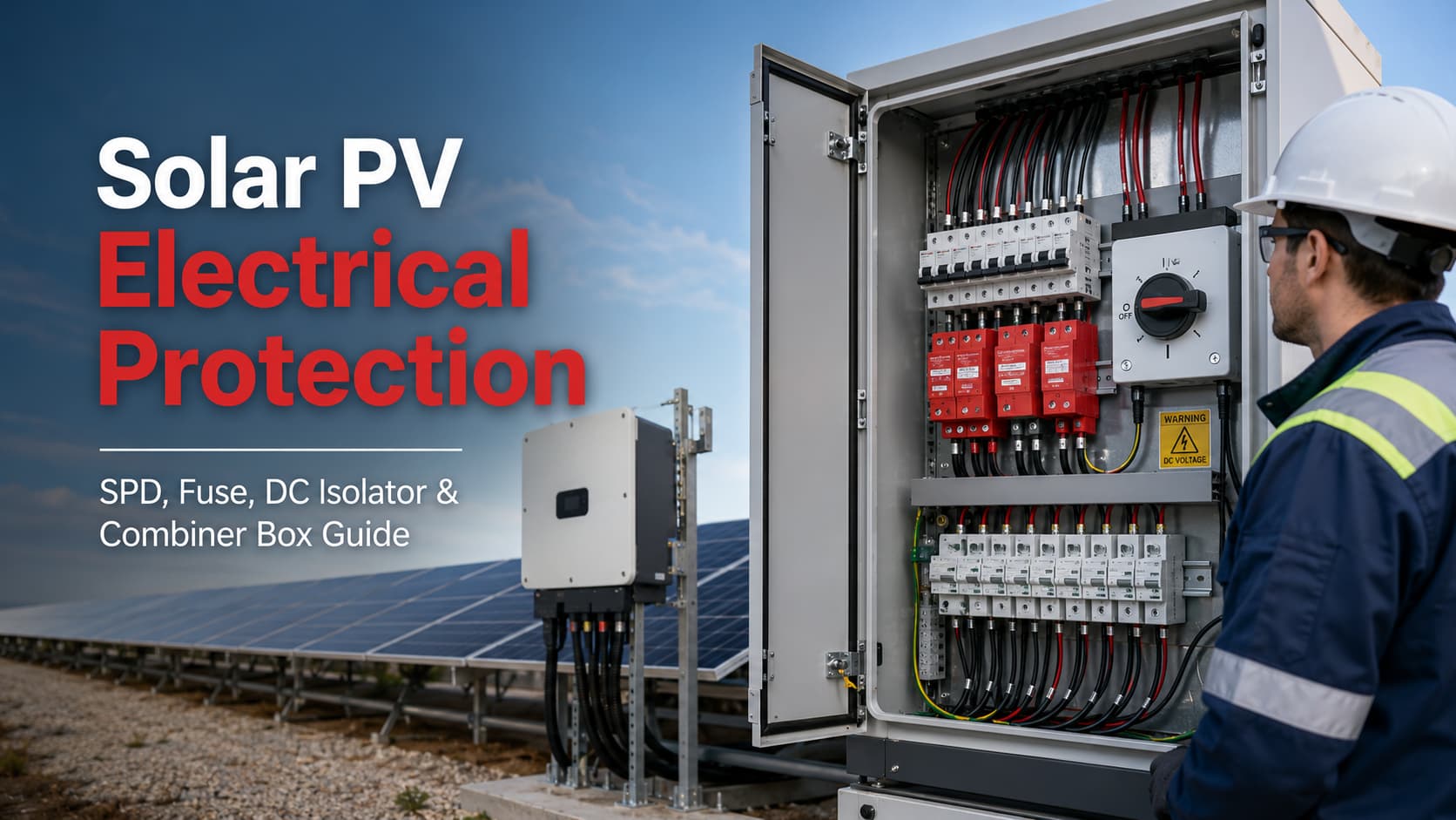
Надежная система солнечной энергетики не зависит от одного защитного устройства. Эффективная Электрическая защита солнечных фотоэлектрических систем требует согласованной защиты по всей цепи постоянного тока — от фотоэлектрических модулей и стрингов до сумматора, инвертора и системы распределения переменного тока.
Базовая логика защиты такова:
Фотоэлектрический модуль → Фотоэлектрический стринг → Предохранитель gPV → Сумматор → УЗИП постоянного тока → Разъединитель постоянного тока → Инвертор → Защита переменного тока
Каждый компонент предназначен для устранения определенного электрического риска:
Самый важный инженерный принцип прост:
Плавкий предохранитель не может заменить УЗИП. УЗИП не может заменить плавкий предохранитель. Разъединитель постоянного тока не является устройством защиты от сверхтоков, а безопасность сумматора (комбайн-бокса) зависит исключительно от качества компонентов и их согласованности внутри него.
Современное проектирование фотоэлектрических массивов регламентируется IEC 62548-1:2023+AMD1:2025, который охватывает требования к электропроводке фотоэлектрических массивов, электрической защите, коммутационным аппаратам и системам заземления. Текущая консолидированная редакция стандарта — IEC 62548-1:2023 с Изменением 1:2025. IEC 60364-7-712:2025 определяет требования к электроустановкам, связанным с системами фотоэлектрического энергоснабжения.
В данном руководстве объясняется, как эти функции защиты работают совместно и как инженеры, EPC-подрядчики, системные интеграторы и проектировщики электроустановок могут создать более скоординированную архитектуру защиты фотоэлектрических систем.
Электрическая защита солнечных фотоэлектрических систем это скоординированное применение устройств электрической защиты и проектных мер, используемых для снижения рисков, возникающих вследствие перегрузки по току, коротких замыканий, обратного тока, переходных перенапряжений, нарушения изоляции, коммутационных операций, электрической дуги и неисправностей оборудования в фотоэлектрических системах.
Фотоэлектрическая установка — это не просто группа солнечных панелей, подключенных к инвертору.
Это система генерации электроэнергии с уникальными рабочими характеристиками.
В отличие от обычной цепи нагрузки переменного тока, фотоэлектрический массив вырабатывает электроэнергию при наличии достаточного солнечного света. Таким образом, сторона постоянного тока может оставаться под напряжением даже после отключения питания переменного тока.
Это различие имеет серьезные последствия для проектирования защиты.
Комплексная стратегия защиты должна учитывать:
Ни один отдельный защитный компонент не может справиться со всеми этими рисками.
Грамотно спроектированная система использует несколько уровней защиты, где каждое устройство выполняет определенную функцию.
Это основа координации Электрическая защита солнечных фотоэлектрических систем.
Фотоэлектрические системы создают ряд электрических условий, которые принципиально отличаются от обычных цепей зданий.
Размыкание главного автоматического выключателя переменного тока не обязательно снимает напряжение с фотоэлектрического массива.
Когда солнечный свет попадает на модули, цепочки могут продолжать генерировать напряжение постоянного тока.
Поэтому обслуживающий персонал может столкнуться с проводниками под напряжением между:
Именно поэтому надлежащая изоляция, маркировка, выбор оборудования и процедуры технического обслуживания имеют важное значение.
Переменный ток естественным образом проходит через ноль дважды в течение каждого электрического цикла. Этот естественный переход тока через ноль может способствовать гашению дуги.
Постоянный ток не имеет такого же периодического перехода через ноль.
В результате коммутационные устройства, предназначенные для применения в цепях переменного тока, не должны автоматически считаться пригодными для высоковольтных фотоэлектрических цепей постоянного тока.
Устройство, используемое в системе постоянного тока напряжением 1000 В или 1500 В, должно быть специально разработано и рассчитано на соответствующее напряжение постоянного тока, силу тока и режим коммутации.
Это относится к:
Неправильный Выбор выключателя-разъединителя постоянного тока может привести к перегреву, невозможности прерывания тока или возникновению устойчивой электрической дуги.
Одиночная фотоэлектрическая цепочка имеет ограниченный ток короткого замыкания.
Однако при параллельном соединении нескольких стрингов исправные стринги могут подавать ток в поврежденный стринг.
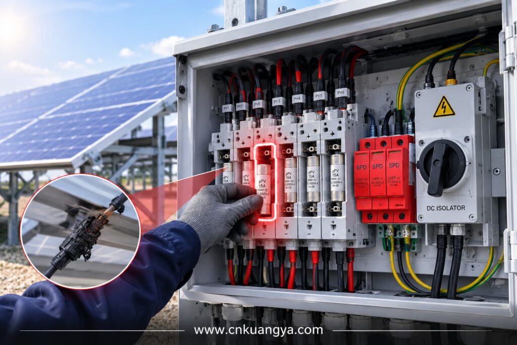
Этот обратный ток может превышать:
Это одна из основных причин, по которой в крупных фотоэлектрических массивах используются стринговые предохранители типа gPV.
Инженерный вопрос заключается не просто в том:
“Какую силу тока вырабатывает одна солнечная панель?”
Более важный вопрос заключается в следующем:
“Какой ток короткого замыкания могут подать другие параллельные цепочки в одну поврежденную цепочку?”
Эта разница имеет решающее значение для правильной координации предохранителей.
Солнечные установки часто включают в себя:
These characteristics can increase exposure to transient overvoltages.
A nearby lightning event does not have to strike a solar panel directly to create damaging voltage impulses.
Electromagnetic coupling into long conductors can produce transient overvoltages capable of stressing:
This is why surge protection must be considered as a system design issue rather than simply an optional accessory.
Electrical components in PV systems may be exposed to:
A protection device that is correctly rated electrically can still fail if the installation environment is ignored.
Надежный Электрическая защита солнечных фотоэлектрических систем therefore depends on both electrical coordination and suitable environmental design.
A simplified PV protection path can be represented as follows:
PV Modules
↓
Струны PV
↓
String Protection / gPV Fuses
↓
Распределительная коробка PV
↓
Защита от перенапряжения постоянного тока
↓
DC Isolation
↓
Солнечный инвертор
↓
AC Surge and Overcurrent Protection
↓
Distribution System / Grid
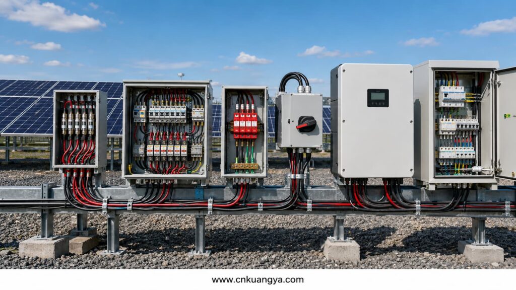
The exact architecture changes according to system size.
For example, a small residential string inverter system may not use a separate external combiner box.
A large commercial or utility-scale plant may include:
The protection principle, however, remains the same.
Every risk should be assigned to the device designed to control it.
| Electrical Risk | Primary Protection Function |
|---|---|
| Reverse string overcurrent | предохранитель gPV |
| Short-circuit or overcurrent | Fuse or suitable protective device |
| Lightning-induced transient | СПД |
| Switching transient | СПД |
| Maintenance disconnection | Изолятор постоянного тока |
| Multiple-string collection | Распределительная коробка |
| Localized component fault | Coordinated protection and isolation |
| Inverter input surge | DC-side SPD |
| AC-side surge | AC SPD |
| Воздействие окружающей среды | Suitable enclosure and component ratings |
The most common design problems occur when these functions are confused, especially when engineers fail to distinguish between a DC fuse and DC SPD.
A gPV fuse is specifically intended for photovoltaic applications.
Its purpose is primarily to protect:
against damaging overcurrents under the conditions that can occur in photovoltaic systems.
PV fuse-links are addressed by IEC 60269-6, which provides supplementary requirements for fuse-links used to protect PV strings and arrays in DC circuits up to 1500V.
The designation gPV is important.
A conventional AC fuse should not automatically be substituted for a fuse designed for photovoltaic DC applications.
PV systems can operate under:
The fuse must be designed and tested for the application.
Not every PV string automatically requires a fuse.
The need for string overcurrent protection depends on system design, including:
Consider a system with many parallel strings.
If one string develops a short circuit, the remaining strings may contribute reverse current into the faulted circuit.
The fuse should disconnect the faulted string before the current causes unacceptable thermal damage to cables, connectors or modules.
In a system with only one string, or in some limited parallel configurations, the available reverse current may not justify individual string fusing.
Поэтому:
The number of PV strings alone should not be used as the only fuse-selection rule.
The engineer must evaluate the possible fault current and the withstand limits of the protected circuit.
A proper gPV fuse selection process should consider at least five parameters.
The fuse voltage rating must be suitable for the maximum possible system voltage.
Common PV fuse voltage classes include:
The selected rating must account for the maximum PV array voltage under expected operating conditions.
Cold weather is particularly important because PV module open-circuit voltage can increase as cell temperature decreases.
A system with a normal operating voltage below 1000V may still experience a higher maximum calculated voltage under low-temperature conditions.
For typical 1000V PV string applications, KUANGYA also provides 10×38 gPV fuse links for solar systems.
The fuse current rating should coordinate with:
Selecting a fuse only because its rated current is slightly above normal operating current is not a sufficient engineering method.
The selected fuse must carry legitimate operating current without nuisance operation while still providing meaningful protection during an abnormal overcurrent condition.
PV module manufacturers generally specify a maximum protective fuse rating or similar limitation.
The selected fuse must not exceed the protection limits established for the module and system design.
A larger fuse may appear to reduce nuisance operation, but oversizing can reduce protection effectiveness.
The fuse must be capable of safely interrupting the available fault current.
Although PV string currents are often lower than industrial short-circuit currents on large AC networks, the breaking capacity should still be verified rather than assumed.
Fuse performance can be influenced by:
A combiner box installed outdoors in a hot climate may experience a much higher internal temperature than the surrounding ambient air.
Protection selection should reflect the actual installation environment.
One common mistake is increasing the fuse rating whenever nuisance operation occurs.
This may hide the actual problem.
Repeated fuse operation can indicate:
Simply installing a larger fuse can allow damaging current to continue for longer.
Correct protection requires investigation, not automatic upsizing.
A surge protective device limits transient overvoltage by diverting surge current away from sensitive equipment.
On the DC side of a PV installation, SPDs may help protect:
IEC 61643-31 covers SPDs intended for the DC side of photovoltaic installations up to 1500V DC, while IEC 61643-32 provides principles for SPD selection, installation and coordination in PV systems.
For an overview of the complete standard family, see our guide to IEC 61643 and Surge Protective Devices.
An SPD is not designed to perform the same function as a fuse.
It does not primarily protect against sustained overcurrent.
It responds to transient overvoltage events.
Transient overvoltages may result from:
A lightning strike near a PV installation can induce a surge into long DC conductors through electromagnetic coupling.
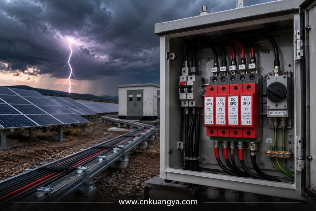
Systems exposed to direct lightning effects require a broader lightning protection assessment and appropriate coordination between the external lightning protection system and electrical SPDs.
Switching operations within electrical networks can also create transient overvoltages.
Long DC cable routes can increase exposure to induced transient energy and create greater separation between protected equipment and the SPD.
A simplified distinction is:
Used where the installation must manage partial lightning current or where the lightning protection design requires Type 1 capability.
Used primarily to protect against induced and switching overvoltages.
Many PV installations use Type 2 DC SPDs where the risk assessment and system design do not require Type 1 capability.
However, device type should not be selected only by habit.
Правильный выбор зависит от:
The SPD must withstand the maximum expected DC voltage of the PV array without entering an unsafe operating condition.
An SPD should not be selected only because its label says “solar.”
Its voltage characteristics must match the system.
Engineers working with 600V to 1500V photovoltaic systems can also review KUANGYA’s Type 2 PV surge protective device for typical DC-side protection applications.
The SPD should limit the transient voltage to a level compatible with the withstand capability of downstream equipment.
Protection coordination matters.
An SPD with an unsuitable protection level may not provide the intended protection to sensitive inverter electronics.
This parameter indicates the SPD’s capability under standardized surge-current conditions.
It should be selected according to the expected surge environment and system design.
Depending on SPD type, the device may be characterized for different surge waveforms and current capabilities.
Engineers should compare actual standardized parameters rather than selecting products solely on marketing descriptions such as “heavy duty.”
The required SPD configuration depends on the PV system topology and earthing arrangement.
Common PV SPD configurations may include different numbers of poles or protective paths.
The system topology must be understood before the SPD is selected.
A correctly selected SPD can still provide poor protection if it is installed incorrectly.
К важным факторам относятся:
Long connecting conductors introduce additional inductive voltage during fast surge events.
As a practical engineering principle:
Keep SPD connection paths as short and direct as the installation permits.
When the PV array and inverter are separated by a long cable distance, a single SPD at only one end may not always provide the desired protection for both ends.
The system should be evaluated as a complete electrical path.
A DC isolator provides a means of disconnecting part of the PV DC circuit.
It supports:
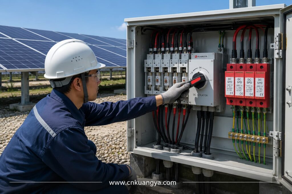
A DC isolator does не automatically replace:
Its primary function is isolation.
This distinction is essential.
High-voltage DC switching can produce sustained electrical arcs.
A DC isolator used in a PV system must therefore be suitable for:
Using an AC-rated switch in a high-voltage DC application can be extremely dangerous.
The physical appearance of two switches may be similar, while their internal switching capability is very different.
A high-resistance connection creates localized heating.
Over time, thermal cycling can worsen the connection and damage:
An isolator rated for a lower DC voltage may fail to interrupt the circuit safely.
Some multi-pole DC isolators depend on a specific pole arrangement to achieve their intended voltage rating.
Incorrect connection can reduce switching capability.
Outdoor isolators may fail because of:
PV systems operate through daily heating and cooling cycles.
Mechanical connections that were initially acceptable can deteriorate if installation quality is poor.
The appropriate location depends on the system architecture.
Possible locations include:
The objective is to provide practical and safe isolation of the relevant circuit section.
A disconnect that is technically present but difficult to access during maintenance may provide limited operational value.
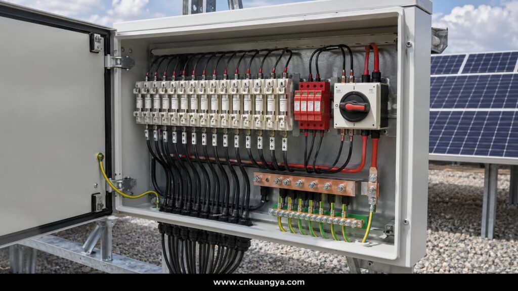
A Распределительная коробка collects the outputs of multiple strings and combines them into one or more larger DC output circuits.
Depending on the design, it may include:
The combiner box therefore sits at one of the most important coordination points in the PV DC system.
A common purchasing mistake is comparing combiner boxes mainly by:
The actual engineering quality depends on what is inside.
Important questions include:
A high IP rating alone does not guarantee electrical safety.
The fuse and SPD have fundamentally different jobs.
Responds to sustained abnormal overcurrent.
Responds to short-duration transient overvoltage.
During normal operation:
During an overcurrent fault:
Во время всплеска напряжения:
This is why describing an SPD as a “surge fuse” is technically misleading.
The two devices should be coordinated but should never be treated as interchangeable, and their position within a solar combiner box wiring diagram should reflect their different protection functions.
A combiner box may contain many current-carrying components in a relatively small enclosure.
Heat can be produced by:
Outdoor solar heating can increase the internal temperature further.
Designers should consider:
Thermal problems often develop gradually.
A connection may operate for months before increasing resistance leads to severe overheating.
Эффективный защита солнечного инвертора is particularly important because the inverter is one of the most valuable and electronically sensitive components in the PV system.
It is also connected to two different electrical environments:
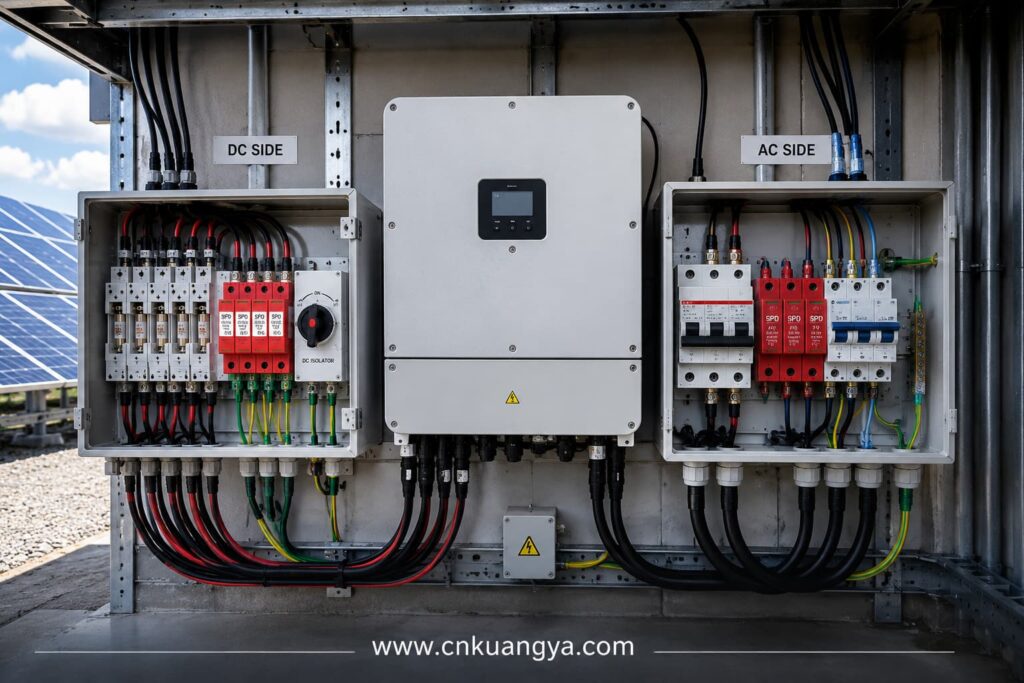
Protection should therefore be considered on both sides.
Potential risks include:
The upstream protection architecture may include:
The exact configuration depends on the inverter design and the PV array architecture.
The AC side may require:
Protecting only the DC side does not create a fully protected inverter.
Surges can reach connected equipment through more than one electrical path.
Modern PV plants may also include:
These circuits should not be ignored when assessing surge pathways.
A system can continue generating electricity while losing critical monitoring or communication capability.
For utility and commercial projects, that can create significant operational problems even when the main inverter remains functional.
This is the central concept of Электрическая защита солнечных фотоэлектрических систем.
Protection devices should not be selected independently.
They must function as a coordinated system.
Use appropriate:
The goal is to protect the circuit against sustained abnormal current.
Use correctly selected:
The goal is to prevent transient voltage from exceeding equipment withstand capability.
Use:
The goal is to allow safe separation of equipment and circuit sections.
Use properly designed:
The goal is to combine protection functions in an organized and maintainable architecture.
Coordinate upstream protection with:
The goal is not merely to protect individual components.
The goal is to control how the entire system responds to abnormal electrical conditions.
Consider ten parallel PV strings connected to one combiner box.
One string develops a serious electrical fault.
Possible sequence:
The SPD does not perform the primary isolation function in this event.
The DC isolator does not automatically trip like a fuse.
Each device has a separate role.
Now consider a nearby lightning event.
Possible sequence:
The gPV fuse may not operate because the event is not simply a sustained string overcurrent.
Again, the correct protection depends on the correct device.
As PV plants move from 1000V to 1500V systems, protection-device coordination becomes increasingly important in large commercial and utility-scale projects.
Higher DC voltage can reduce current for a given power level and may reduce certain balance-of-system requirements.
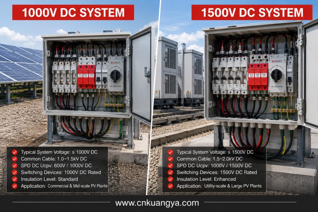
However, increasing system voltage also increases protection demands.
For a 1500V DC system, engineers must verify that all applicable components are suitable for the required voltage.
This may include:
A 1500V SPD does not make a combiner box a 1500V system if another internal component is rated for only 1000V.
The complete assembly is limited by its weakest relevant component.
Higher voltage places greater demands on:
Pollution and moisture can further influence insulation performance.
Interrupting a high-voltage DC circuit requires equipment designed for that duty.
The correct isolator or breaker should be selected according to the actual circuit configuration.
PV module voltage increases when module temperature decreases.
Designers should calculate the maximum array open-circuit voltage under the minimum expected temperature conditions.
Using only the module’s standard test condition voltage can lead to an underspecified protection system.
Many inverters include internal protective functions.
However, internal protection does not automatically eliminate the need for external:
The full system architecture must be evaluated.
An AC fuse should not be assumed suitable for high-voltage DC interruption.
Use a fuse specifically designed and rated for the PV application.
System voltage is only one parameter.
Engineers should also review:
Long conductors can reduce effective surge protection.
Connection paths should be designed to be short and direct.
An isolator and an overcurrent protective device are not automatically the same thing.
The device function must match the protection requirement.
A larger fuse may reduce protection.
The cause of repeated fuse operation should be investigated.
High internal temperature can affect:
Thermal design should be evaluated under realistic outdoor conditions.
One lower-rated component can compromise the entire high-voltage assembly.
The inverter is connected to both DC and AC electrical systems.
A complete protection assessment should consider both.
Large PV systems should have a clear protection architecture showing:
Protection should be designed as a system rather than purchased as a collection of unrelated products.
A structured engineering workflow reduces selection errors.
Record:
Рассмотрите:
Verify that the result remains within the rating of every relevant DC component.
Determine:
Decide whether individual string fusing is required.
Проверьте:
Evaluate:
Then select the appropriate SPD type and ratings.
Determine where safe disconnection is required for:
Select appropriately rated DC isolators.
Coordinate:
Check:
Do not stop at the inverter DC terminals.
Evaluate:
Before commissioning, confirm that no component creates a weak point.
This final system-level review is what transforms individual devices into coordinated Электрическая защита солнечных фотоэлектрических систем.
Protection devices require inspection throughout the life of the PV installation.
Ищите:
Check:
SPDs can degrade after repeated surge exposure.
Проверьте наличие:
Ищите:
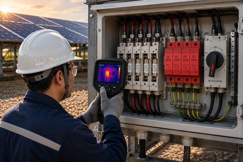
Thermal imaging can be useful for identifying developing high-resistance connections in operating equipment.
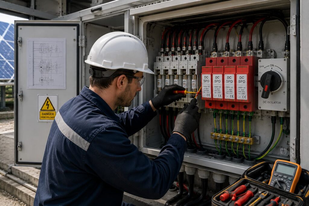
Before approving a PV protection design, verify the following.
Solar PV Electrical Protection is the coordinated use of fuses, SPDs, isolators, breakers, combiner boxes and other protective measures to reduce electrical risks throughout a photovoltaic system.
Нет.
The requirement depends on the number of parallel strings, possible reverse current, conductor ratings, module limitations and applicable design rules.
The fault-current scenario should be evaluated rather than assuming that every string always requires a fuse.
Sometimes a correctly selected PV DC circuit breaker may perform an overcurrent protection function, but devices are not automatically interchangeable.
The correct solution depends on:
Нет.
An SPD protects mainly against transient overvoltage.
A fuse protects against sustained abnormal overcurrent.
They perform different functions.
A fuse is not the primary protective device for transient overvoltage.
An appropriately selected SPD is used for surge protection.
A DC isolator primarily provides safe disconnection.
A circuit breaker may provide switching and protective functions depending on its design and ratings.
The terms should not be used interchangeably without checking the actual device function.
Possible locations include:
The correct arrangement depends on cable length, system architecture and surge protection design.
Не всегда.
Long cable distances, multiple system zones and exposure conditions may require protection at more than one location.
The complete surge path should be evaluated.
The SPD must be selected according to the actual maximum PV system voltage and its required electrical characteristics.
A 1500V system requires components suitable for the relevant maximum voltage, but simply choosing the highest voltage label is not automatically the best protection strategy.
A PV combiner box combines the outputs of multiple PV strings and may integrate:
Нет.
Ingress protection is important, but electrical safety also depends on:
Depending on the project and jurisdiction, important references may include:
The applicable edition, national adoption and local electrical regulations should always be confirmed for the specific project.
Надежный Электрическая защита солнечных фотоэлектрических систем is not achieved by adding more protective devices without a system plan.
It is achieved by giving every device a clearly defined responsibility.
Используйте предохранитель gPV to address appropriate overcurrent and reverse-current risks.
Используйте DC SPD to limit transient overvoltages.
Используйте Изолятор постоянного тока to provide safe electrical disconnection.
Используйте Распределительная коробка to integrate string collection and protection in a controlled electrical environment.
Then coordinate all of these elements with the inverter, cables, PV modules, AC system and project operating conditions.
The most important design question should never be:
“Which protection product should we add?”
The better question is:
“What electrical failure are we trying to control, which device is responsible for controlling it, and how does that device coordinate with the rest of the PV system?”
That system-level approach is the foundation of effective Электрическая защита солнечных фотоэлектрических систем.
For modern 1000V and 1500V photovoltaic projects, protection coordination becomes increasingly important as system voltage, power density and equipment value increase.
A well-designed PV system should therefore treat protection as an integrated architecture:
Detect the risk.
Limit the fault.
Isolate the affected circuit.
Protect critical equipment.
Maintain safe operation.
That is the difference between installing individual protective components and engineering a complete solar PV electrical protection system.

