温州市岳陽工業区 325000
勤務時間
月曜日~金曜日:午前7時~午後7時
週末午前10時~午後5時
温州市岳陽工業区 325000
勤務時間
月曜日~金曜日:午前7時~午後7時
週末午前10時~午後5時

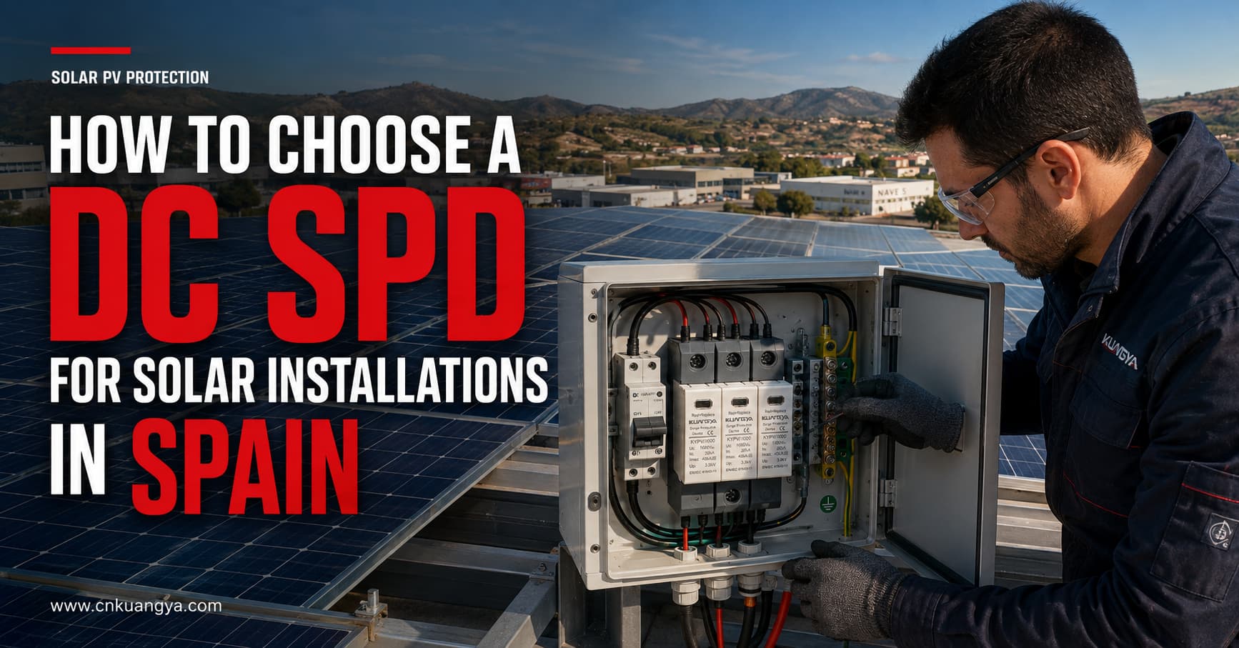
太陽光発電システムは、近隣の落雷活動、開閉操作、および接続された電気回路を通じて伝播する外乱によって引き起こされる過渡過電圧にさらされています。これらの事象は、インバータ、監視装置、接続箱、およびその他の精密部品を損傷させる可能性があります。.
適切な スペインの太陽光発電設備向け直流SPDの選定には 単に公称システム電圧に適合するデバイスを選ぶだけでは不十分です。設計者および施工者は、最大太陽電池開放電圧、SPDの分類、放電耐量、電圧保護レベル、システムの接地方式、ケーブル長、設置場所、および適用規格も考慮しなければなりません。.
しかし、直流SPDの選定には、単に公称システム電圧に適合するデバイスを選ぶ以上の検討が必要です。設計者および施工者は、最大太陽電池開放電圧、SPDの分類、放電耐量、電圧保護レベル、システムの接地方式、ケーブル長、設置場所、および適用規格も考慮しなければなりません。.
本ガイドでは、スペインの太陽光発電設備向け直流SPDの選定方法を解説し、見積依頼前に確認すべき技術情報について説明します。.
太陽光発電モジュールおよびその接続ケーブルは、通常、広範囲にわたる露出した場所に設置されます。長いDCケーブル経路は、雷サージや開閉サージによる過渡過電圧がインバータに到達する経路となる可能性があります。.
サージは必ずしも太陽光発電アレイへの直撃雷によって発生するとは限りません。近傍の落雷がDCケーブルに過渡電圧を誘起する場合があるほか、設備内の開閉操作によっても電気的障害が発生する可能性があります。.
DC SPD(サージ防護デバイス)の目的は以下の通りです:
SPDは、ヒューズ、回路遮断器(ブレーカー)、アイソレーター、接地システム、または外部雷保護システムの代わりにはなりません。各デバイスは異なる保護機能を果たしており、完全な太陽光発電(PV)設計の一部として調整される必要があります。.
スペインの低圧電気設備は、一般にREBTとして知られる低圧電気技術規則(Reglamento Electrotécnico para Baja Tensión)によって管理されています。適用される設計においては、現行の技術指示書、プロジェクト仕様書、地域の要件、および同規則が参照する規格も考慮しなければなりません。.
REBTに関連するスペインの公式規格リストは以下の通りです:
国際的な太陽光発電(PV)用途においては、以下のIEC規格も重要です:
IEC 61643-31は、定格電圧1,500V DC以下の太陽光発電設備の直流側に接続されるSPDに適用されます。.
プロジェクトの要件は、設置タイプ、リスク評価、場所、インバータの設計、外部雷保護システム、およびスペイン当局または認定施工業者の要件によって異なる場合があります。したがって、製品の選定はプロジェクト設計者または有資格の電気技術者によって確認される必要があります。.
最初の選定パラメータは、PVシステムにおけるSPDの最大連続動作電圧であり、通常は次のように識別されます。 Ucpv.
インバータの定格動作電圧のみに基づいてSPDを選定しないでください。.
PVストリングの最大電圧は、以下に依存します。
PVモジュールの電圧は温度が下がると上昇します。そのため、ストリング全体の最大低温時開放電圧は、標準試験条件下の値よりも高くなる可能性があります。.
SPDのUcpvは、PVアレイに継続的に印加される可能性のある最大電圧に適したものでなければなりません。.
| PVシステム | 一般的なSPD電圧クラス | 重要な確認事項 |
|---|---|---|
| 小規模住宅用PVシステム | 600 V DC | 最大冷間時ストリング開放電圧(Voc)を確認する |
| 住宅用または商業用太陽光発電(PV) | 1,000 V DC | インバータおよびストリングの電圧制限を確認すること |
| 産業用またはメガソーラー規模の太陽光発電 | 1,500 V DC | 1,500 V PVシステム専用に設計されたSPDを使用すること |
これらは適用例であり、自動選定ルールではありません。最終的なSPD電圧は、計算された最大PV電圧およびメーカーの結線図に基づいて決定する必要があります。.
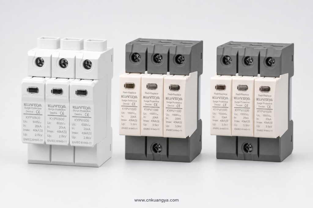
Ucpvが不十分なSPDを選択すると、早期動作、過熱、または切断の原因となる可能性があります。必要以上に高い電圧定格を選択すると、電圧防護レベルが高くなり、精密機器に対する保護効果が低下する可能性があります。.
PV用SPDは、通常、対応可能なサージ電流に応じて分類されます。.
タイプ2 SPDは、誘導雷サージおよび開閉サージから保護するために一般的に使用されます。.
代表的な用途は以下の通り:
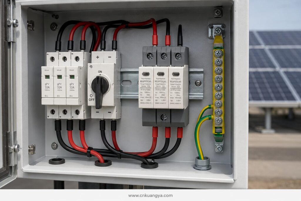
タイプ2デバイスは、通常、公称放電電流を用いて規定される。 で および最大放電電流 アイマックス, (8/20 μsの電流波形に基づく)。.
タイプ1 SPDは、雷電流の一部を放電するように設計されている。雷保護設計において、電気設備内に雷電流が流入する可能性があると示される場合に必要となることがある。.
タイプ1の選定は、一般的に以下に関連する:
タイプ1の性能は、通常、インパルス放電電流を用いて表現される インプ, 10/350 μs波形に基づく。.
タイプ1+2 SPDは、雷電流保護と誘導サージ保護を1つのデバイスに統合したものである。.
以下の場合に検討される:
SPDのタイプは、プロジェクトの雷保護コンセプトに基づいて選定しなければなりません。単にタイプ番号が大きい方が高性能であるという理由だけで選定してはなりません。.
SPDの各定格は、性能の異なる側面を表しています。.
で 指定された試験条件下で、タイプ2 SPDが繰り返し放電可能な電流を示し、通常は8/20 μsの波形が使用されます。.
タイプ2 SPDを比較する際に使用される主要な定格の一つです。.
アイマックス 指定された試験条件下でSPDが処理可能な最大8/20 μsの放電電流です。.
Imaxの定格が高いというだけで、そのSPDが特定の設備に適しているとは限りません。In、Up、Ucpv、短絡特性、接続構成、および適用される試験規格と併せて検討する必要があります。.
インプ タイプ1およびタイプ1+2デバイスに使用され、10/350 μsの波形を用いた雷インパルス電流耐量を示します。.
タイプ1の保護が必要な場合は、プロジェクト仕様に従って、極ごとまたは保護モードごとのIimp値を比較してください。.
上へ 指定された放電試験中にSPDの両端に現れる残留電圧を示します。.
The Up value should be lower than the impulse withstand level of the equipment being protected. Connection cables also add voltage during a surge, so the effective protection level at the inverter can be higher than the SPD’s catalogue value.
This is why short, direct SPD connections are essential.
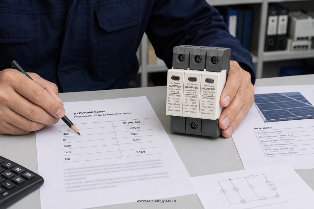
A PV DC circuit may be floating, functionally earthed, or configured according to a specific inverter topology. The SPD must use a connection arrangement suitable for that system.
Before selecting the number of poles or protection modes, confirm:
Do not assume that an AC SPD with a similar voltage can be used on the PV DC side. PV systems have specific continuous-voltage and fault-current characteristics. The device should be designed and tested for photovoltaic DC applications according to IEC/UNE-EN 61643-31.
A PV SPD must be able to disconnect safely if it reaches the end of its service life.
Important parameters include:
The external backup fuse should not be selected only according to the SPD’s physical size. Follow the SPD manufacturer’s data sheet and verify compatibility with the PV string current and the system’s fault characteristics.
The SPD protects against transient overvoltage. The gPV fuse or DC breaker protects against overcurrent and short-circuit conditions. One device cannot replace the other.
Typical DC SPD locations include:
The most suitable arrangement depends on cable length, exposure, lightning protection design, equipment withstand level, and project risk assessment.
For a compact rooftop installation with short DC cable routes, a Type 2 SPD near the inverter may provide the required protection when permitted by the design.
For longer routes between the PV array and inverter, coordinated SPDs may be required at both ends. This reduces the voltage stress that can develop along the cable and improves protection for equipment at each location.
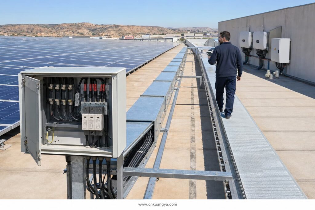
Some industry design guidance uses approximately 10 metres as a point at which additional coordination should be considered. This should not be treated as a universal rule for every Spanish installation. The final placement must follow the applicable design standard, risk assessment, cable routing, and equipment manufacturer’s instructions.
Even a correctly rated SPD can provide poor protection if it is installed with long or badly routed cables.
During a surge, cable inductance creates additional voltage. Longer conductors can therefore increase the total voltage reaching the inverter.
Good installation practice includes:
The objective is to reduce the total connection length and minimise the effective protection level at the protected equipment.
DIN-rail SPD modules do not automatically provide outdoor protection. Their environmental protection depends on the enclosure in which they are installed.
For rooftop and outdoor PV systems in Spain, check:
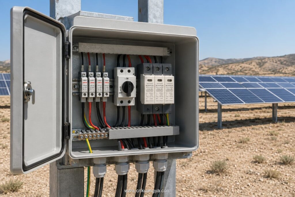
The SPD’s declared ratings apply under the operating conditions stated in its data sheet. High internal cabinet temperatures should be considered, especially in outdoor enclosures exposed to direct sunlight.
SPDs are not permanent, maintenance-free components. Their protective elements can deteriorate after repeated surge events.
Useful maintenance features include:
The module should be inspected according to the maintenance plan and after significant lightning activity or a known surge event.
Replace the module when:
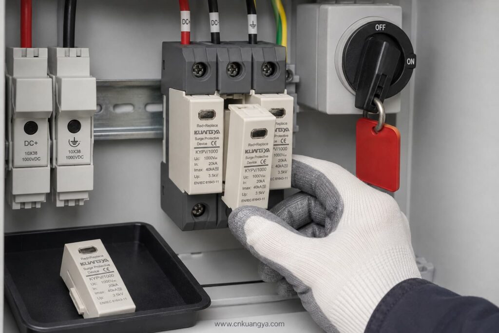
Always isolate the relevant DC circuit and follow safe working procedures before inspection or replacement.
| Project Condition | SPD Selection to Evaluate |
|---|---|
| Residential rooftop PV without expected lightning-current entry | Type 2 PV DC SPD |
| Commercial rooftop with long DC cable routes | Coordinated Type 2 SPDs at suitable locations |
| Building with an external lightning protection system | Type 1 or Type 1+2, depending on the lightning protection design |
| Utility-scale 1,500 V PV array | PV-specific 1,500 V SPD with suitable Type and discharge ratings |
| Combiner box exposed to induced surges | Type 2 PV DC SPD |
| Inverter requiring combined lightning and surge protection | Type 1+2 PV DC SPD if specified by the design |
This table is a preliminary guide only. It does not replace the project risk assessment or the work of an authorised electrical designer.
Providing complete technical information helps the supplier select the correct product and prevents delays.
Send the following details:
If the SPD type is not yet confirmed, provide the PV module data, number of modules per string, minimum design temperature, inverter model, system drawing, and lightning protection information.
Avoid these common errors:
Selecting a suitable スペインの太陽光発電設備向け直流SPDの選定には requires coordination between the PV system voltage, lightning risk, SPD classification, installation location, earthing arrangement, and applicable Spanish requirements.
The most important steps are:
KUANGYA supplies DC SPDs for solar PV applications in 600 V, 1,000 V, and 1,500 V configurations, including Type 2 and Type 1+2 options.
View the KUANGYA DC SPD range for photovoltaic systems or contact us with your system voltage, SPD type, discharge-current requirements, wiring configuration, quantity, and project location to request a data sheet and B2B quotation.
Not automatically. Type 2 is widely used for induced lightning and switching surges, but the final selection depends on the lightning protection system, risk assessment, equipment location, and project requirements.
Only if the SPD’s Ucpv is suitable for the maximum calculated PV voltage under the lowest expected temperature. Do not rely only on the nominal system description.
In is the nominal discharge current used to evaluate repeated Type 2 surge performance. Imax is the maximum 8/20 μs discharge current the SPD can withstand under specified test conditions.
It is used where the design requires both partial lightning-current discharge and Type 2 surge-limiting performance at the same installation point.
Common locations include the combiner box and inverter DC input. Long cable routes or exposed systems may require coordinated SPDs at more than one location.
UNE-EN 61643-31 is the principal Spanish standard covering requirements and test methods for SPDs used in photovoltaic installations. The complete installation must also follow the REBT and other applicable technical requirements.
If your project has already reached the stage of deciding between Type 1, Type 2 and Type 1+2 protection, continue with our detailed guide to Type 1 vs Type 2 SPD for solar PV in Spain.
This article provides general technical guidance. Final SPD selection and installation should be verified by the responsible project designer or an authorised electrical professional in accordance with current Spanish requirements.

