Zone industrielle WengYang Yueqing Wenzhou 325000
Heures de travail
Du lundi au vendredi : de 7h00 à 19h00
Le week-end : 10H00 - 17H00
Zone industrielle WengYang Yueqing Wenzhou 325000
Heures de travail
Du lundi au vendredi : de 7h00 à 19h00
Le week-end : 10H00 - 17H00

Un parafoudre protège les équipements électriques contre les surtensions transitoires, mais qu'est-ce qui protège le parafoudre en cas de défaut interne ou de court-circuit ?
C'est là que le fusible ou disjoncteur de protection de secours du parafoudre devient important.
Cependant, il n'existe pas de règle universelle telle que :
“ Chaque parafoudre de type 2 nécessite un fusible de 125 A. ”
ou :
“ Un parafoudre de 40 kA doit utiliser un disjoncteur de 40 A. ”
Les deux affirmations peuvent être fausses.
Correct Fusible de protection du parafoudre La sélection dépend du modèle exact de parafoudre, de la protection contre les surintensités en amont, du courant de court-circuit présumé, de la section des conducteurs, de la configuration du système et des instructions du fabricant.
Certains parafoudres peuvent utiliser le fusible ou le disjoncteur amont existant. D'autres nécessitent une protection de secours séparée. Certains produits intègrent même la protection de secours directement dans le parafoudre.
La règle la plus importante est donc simple :
Ne sélectionnez pas un fusible de protection pour parafoudre uniquement en fonction de son In, de son Imax ou de sa classification de type. Vérifiez toujours la protection de secours déclarée par le fabricant et les conditions réelles d'installation.
Un parafoudre peut nécessiter un fusible ou un disjoncteur de protection, mais chaque installation n'en requiert pas nécessairement un séparé.
Si le dispositif de protection contre les surintensités en amont existant satisfait déjà aux exigences de protection définies par le fabricant du parafoudre, un fusible de protection supplémentaire peut ne pas être nécessaire.
Si le dispositif de protection en amont dépasse la valeur autorisée par le fabricant, ou si les instructions du parafoudre spécifient une protection de dérivation dédiée, un dispositif supplémentaire fusible ou disjoncteur de protection de secours du parafoudre peut être nécessaire.
Cela signifie que la bonne question n'est pas simplement :
“ Quelle taille de fusible dois-je installer ? ”
Posez plutôt la question suivante :
“La protection amont existante satisfait-elle déjà aux exigences spécifiques de ce parafoudre ?”
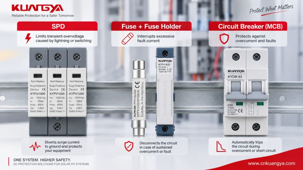
Un parafoudre et un dispositif de protection contre les surintensités résolvent des problèmes électriques différents.
Un parafoudre de puissance typique est connecté en parallèle avec le circuit.
En fonctionnement normal, il ne transporte que peu ou pas de courant de charge. Lorsqu'une surtension transitoire survient, le parafoudre devient conducteur et dévie le courant de choc à travers son chemin de protection conçu à cet effet.
Un fusible ou un disjoncteur a une fonction différente.
Sa fonction principale est d'interrompre les surintensités prolongées ou les courants de défaut.
| Dispositif | Fonction principale | Conçu principalement pour |
|---|---|---|
| DOCUP | Limite les surtensions transitoires et dévie les courants de foudre | Phénomènes transitoires de foudre et de commutation |
| Fusible | Interrompt les courants excessifs | Surcharge et court-circuit |
| Disjoncteur | Interrompt les courants excessifs et assure l'isolation/la commutation | Surcharge et court-circuit |
| Déconnecteur interne de parafoudre | Déconnecte un élément de protection défaillant ou en surchauffe | Fin de vie du parafoudre ou condition interne anormale |
Par conséquent :
Un parafoudre n'est pas un fusible
et :
Un fusible n'est pas un parafoudre
Ils offrent une protection complémentaire.
De nombreux parafoudres à limitation de tension utilisent des composants non linéaires tels que des varistances à oxyde métallique.
En tension nominale du système, l'élément de protection reste à haute impédance.
Lors d'une surtension, son comportement électrique change rapidement et il conduit le courant de surtension.
Cependant, les composants de protection contre les surtensions peuvent finir par atteindre leur fin de vie ou être endommagés en raison de :
Si un élément de protection développe un défaut à faible impédance, l'installation doit être capable de déconnecter en toute sécurité le courant de défaut à fréquence industrielle ou le courant continu résultant.
C'est pourquoi les fiches techniques des parafoudres peuvent inclure des paramètres tels que :
Pour les parafoudres basse tension CA, la norme internationale actuelle est IEC 61643-11:2025, qui couvre les exigences et les méthodes d'essai pour les parafoudres connectés aux circuits CA jusqu'à 1 000 V RMS.
IEC 61643-11:2025 — page officielle de l'IEC
Une question courante est :
“ Si mon parafoudre possède déjà un déconnecteur interne, pourquoi aurait-il besoin d'un autre fusible ? ”
Parce qu'ils n'assurent pas nécessairement la même fonction.
Le déconnecteur interne est généralement associé au composant de protection contre les surtensions à l'intérieur du parafoudre.
Par exemple, lorsqu'une varistance (MOV) atteint une condition thermique dangereuse, le mécanisme interne peut déconnecter l'élément défaillant.
Sur de nombreux parafoudres modulaires, cette condition est liée mécaniquement à un indicateur d'état.
La fenêtre peut passer du vert au rouge, selon la conception du fabricant.
Le fusible ou le disjoncteur externe fait partie de la protection contre les courants de défaut et de la coordination de l'installation.
Selon le parafoudre (SPD), il peut aider à :
Par conséquent :
Un déconnecteur thermique interne ne doit pas être automatiquement considéré comme un remplacement pour un fusible de protection externe du parafoudre.
La documentation du produit doit toujours être vérifiée.
Non.
Il existe trois situations courantes.
| Condition d'installation | Protection de secours séparée |
|---|---|
| Le dispositif amont existant est conforme aux conditions autorisées par le fabricant du parafoudre | Souvent non requis |
| Le dispositif amont existant dépasse la limite autorisée par le fabricant | Une protection dédiée peut être nécessaire |
| Le parafoudre dispose d'une protection de secours intégrée testée | Un dispositif de secours supplémentaire peut ne pas être requis sous certaines conditions spécifiées |
Il s'agit de l'un des points les plus importants dans Protection de secours pour parafoudre.
Vous ne pouvez pas prendre la décision en utilisant uniquement :
Deux parafoudres de type 2 ayant des tensions et des courants Imax similaires peuvent avoir des exigences de protection de secours différentes.
Les schémas d'installation des parafoudres utilisent souvent deux désignations :
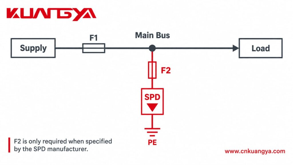
F1 = dispositif de protection du système en amont
F2 = dispositif de protection de secours dédié au parafoudre
Un agencement simplifié peut ressembler à ceci :
Alimentation → F1 → Système de distribution
avec le parafoudre connecté en parallèle via F2 là où une protection F2 dédiée est requise.
Lors de la sélection d'un Fusible de protection du parafoudre, la première question ne devrait donc pas être :
“ Quelle taille de fusible dois-je acheter ? ”
Demandez plutôt :
“ Le dispositif F1 existant peut-il déjà assurer la protection requise par ce parafoudre ? ”
Si F1 respecte les conditions du fabricant, F2 peut ne pas être nécessaire.
Si F1 est supérieur à la valeur autorisée, un dispositif F2 dédié peut être nécessaire.
Ce principe est clairement démontré dans plusieurs guides d'installation publiés par les fabricants, que nous examinerons plus tard.
Il n'existe pas de taille Fusible de protection du parafoudre universelle.
Commencez toujours par la fiche technique ou les instructions d'installation exactes du fabricant.
Recherchez des formulations telles que :
Ne prenez pas la valeur d'un fusible d'un autre parafoudre simplement parce que les deux appareils sont de type 2 ou ont tous deux un Imax = 40 kA.
Product construction and tested coordination can be different.
Suppose an SPD manufacturer allows:
Maximum upstream protection = 125 A gG
and the system already has:
F1 = 63 A gG
If all other manufacturer requirements are satisfied, the existing upstream fuse may already provide the necessary protection.
Installing another 125 A fuse does not automatically make the installation safer.
Now consider:
F1 = 250 A gG
If the SPD is only approved with a maximum 125 A gG backup arrangement, the existing 250 A protection may no longer satisfy the SPD requirements.
A dedicated Fusible de protection du parafoudre may then be necessary.
This is why F1 must be checked before adding F2.
Fuse ampere rating alone is not enough.
You must also consider the available fault current at the installation point.
The same SPD can face very different fault conditions depending on where it is installed.
Par exemple :
A small downstream distribution board may have relatively low prospective short-circuit current.
A main industrial panel close to a transformer can have significantly higher available fault current.
Therefore, always evaluate the combination of:
SPD + backup protection + available short-circuit current
Ceci est particulièrement important dans :
Consider a Type 2 SPD marked:
In = 20 kA
Imax = 40 kA
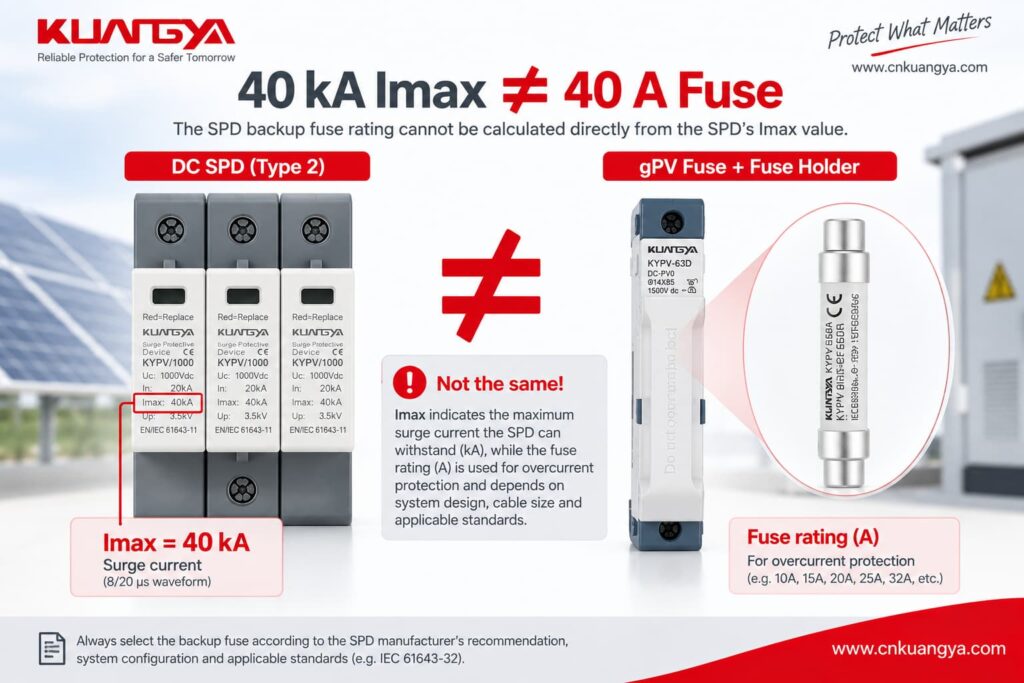
A very common mistake is:
“The SPD is 40 kA, so it should use a 40 A fuse.”
That is incorrect.
Imax = 40 kA describes a surge-current characteristic associated with the relevant impulse waveform.
A 40 A fuse is an overcurrent protective device rating.
These values describe different electrical phenomena.
Par conséquent :
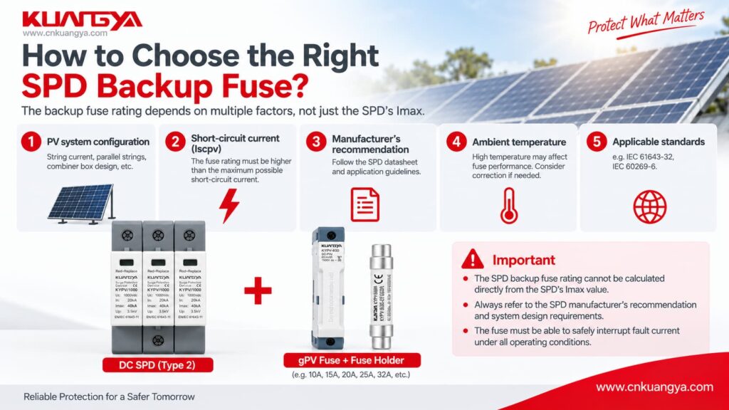
The SPD backup fuse rating cannot be calculated directly from the SPD’s Imax value.
If you are unsure about the difference between In, Imax, Up and Iscpv, see our guide des spécifications des parafoudres CC.
Understanding these parameters prevents one of the most common SPD selection errors.
The manufacturer’s maximum backup-fuse value does not mean that the largest permitted fuse should always be installed.
The protective device must also coordinate with:
For example, if an SPD permits a maximum backup fuse of 125 A, that does not automatically mean every installation should use a 125 A fuse.
Maximum is a limit, not always a recommendation.
A fuse and a circuit breaker can both provide overcurrent protection, but their operating characteristics are different.
| Facteur | Fusible | Disjoncteur |
|---|---|---|
| Replacement after operation | Must normally be replaced | Can normally be reset after investigation |
| Time-current behavior | Depends on fuse class and rating | Depends on breaker type and trip curve |
| Short-circuit capability | Can be very high | Depends on breaker breaking capacity |
| Surge impulse behavior | Depends on fuse characteristics | Depends on breaker characteristics |
| Isolation | Requires suitable holder/switching arrangement | Often convenient |
| Coordination | Must match SPD data | Must match SPD data |
Par conséquent :
Do not assume that a 125 A gG fuse can automatically be replaced by a 125 A circuit breaker.
Manufacturers can specify different protective-device combinations.
For example, Schneider Electric publishes coordination tables pairing particular SPD models with specific protective-device ratings rather than applying one universal breaker value.
Do not copy an AC SPD backup-protection rule directly into a photovoltaic DC system.
PV systems have different:
SPDs designed specifically for the DC side of photovoltaic installations are covered by IEC 61643-31:2018, which applies to PV DC SPDs up to 1,500 V DC.
IEC 61643-31:2018 — official IEC page
This is why an AC SPD backup-fuse example should never automatically be applied to a 1,000 V or 1,500 V PV system.
The following SPD backup fuse examples come from published manufacturer technical information.
They are useful because they demonstrate that backup-protection requirements vary significantly between products.
Do not copy these values to another SPD without checking its own datasheet.
| Manufacturer Example | Published Information | What It Demonstrates |
|---|---|---|
| Schneider Electric Resi MAX | Backup fuse only required if not already provided in mains; published table shows no F2 required in one F1 ≤125 A / Isc <50 kA arrangement | Existing upstream protection may sometimes provide the required backup protection |
| Phoenix Contact VAL-SEC | Published guidance allows installation without additional F2 up to specified upstream conditions; if dedicated F2 is used, 125 A gG is recommended in the example | F2 is not automatically required |
| DEHNguard SE CI | Integrated backup fuse; manufacturer states no additional backup fuse required up to its specified 25 kArms short-circuit condition | Backup protection can be integrated into the SPD |
Let’s look at these examples more closely.
Schneider Electric’s Resi MAX installation instructions provide an especially useful example.
For the documented SPD arrangement, Schneider states that the backup fuse is:
required only if suitable protection is not already provided in the mains.
The document lists ≤125 A gL/gG backup protection and shows a case where:
F1 ≤125 A
et :
Isc <50 kA
can result in:
No need for F2
under the manufacturer’s stated conditions.
Schneider Electric Resi MAX SPD installation instructions
This is an excellent example of why installing an additional fuse automatically is not always correct.
Phoenix Contact provides a useful Type 2 SPD backup-fuse example for its VAL-SEC range.
Its published technical guidance explains that the device can be installed in the branch line without an additional F2 under specified upstream protection conditions.
Where a dedicated F2 is nevertheless required or desired, the document gives:
125 A gG
as an appropriate value for the example.
More importantly, Phoenix Contact also warns against selecting certain smaller backup fuses below 80 A gG in that specific arrangement because their impulse withstand may result in unwanted operation during surge events.
Phoenix Contact — The Right Backup Fuse for Surge Protective Devices
Ceci fait pas mean that every Type 2 SPD needs an 80 A or 125 A fuse.
It demonstrates something more important:
An SPD backup fuse must be coordinated with the specific SPD. Choosing the smallest possible fuse is not automatically the safest option.
Not every SPD requires an external backup fuse.
DEHN’s DEHNguard SE CI Type 2 SPD includes an integrated backup fuse.
DEHN states that no additional backup fuse is required for installations within the product’s specified maximum short-circuit current of 25 kArms.
DEHNguard SE CI with integrated backup fuse
This example shows why the statement:
“Every SPD must have a separate external fuse.”
is incorrect.
The correct arrangement depends on the tested product design.
Oui.
A smaller fuse is not automatically safer.
The protective device must be capable of remaining intact during the surge conditions that the SPD is intended to handle while still interrupting a sustained fault when required.
If an undersized fuse operates unnecessarily during a surge, the SPD can become disconnected.
The electrical installation may then continue operating normally while surge protection has been lost.
This can be particularly difficult to notice in a parallel-connected SPD.
Phoenix Contact’s published example illustrates this issue by warning against certain undersized gG backup fuses in the specific Type 2 SPD arrangement described above.
Again:
This is a product-specific example, not a universal minimum fuse value.
Oui.
If the external protective device exceeds the maximum value permitted by the SPD manufacturer, the SPD may no longer be operating within the tested fault-protection arrangement.
For example, if a product states:
Maximum backup fuse: 125 A gG
this should not be interpreted as:
“125 A must always be installed.”
Instead it means that the protection arrangement should not exceed the manufacturer’s stated limit unless another approved configuration is provided.
The actual selection must still consider:
Consider a Type 2 SPD in a small commercial distribution board.
Assume:
Main upstream fuse F1 = 63 A gG
and the selected SPD permits:
Maximum upstream protection = 125 A gG
If:
then the existing 63 A upstream device may already provide the required backup protection.
Adding a second 125 A fuse would not automatically improve the system.
Now consider a larger industrial panel.
Assume:
F1 = 400 A
while the SPD permits:
Maximum backup protection = 125 A gG
The upstream protection now exceeds the manufacturer’s stated limit.
A dedicated F2 may therefore be required.
The simplified arrangement may become:
400 A upstream protection → SPD branch → approved F2 → SPD
However, the designer must still verify:
This is why a backup-protection arrangement that works in a small distribution board cannot simply be copied into an industrial main panel.
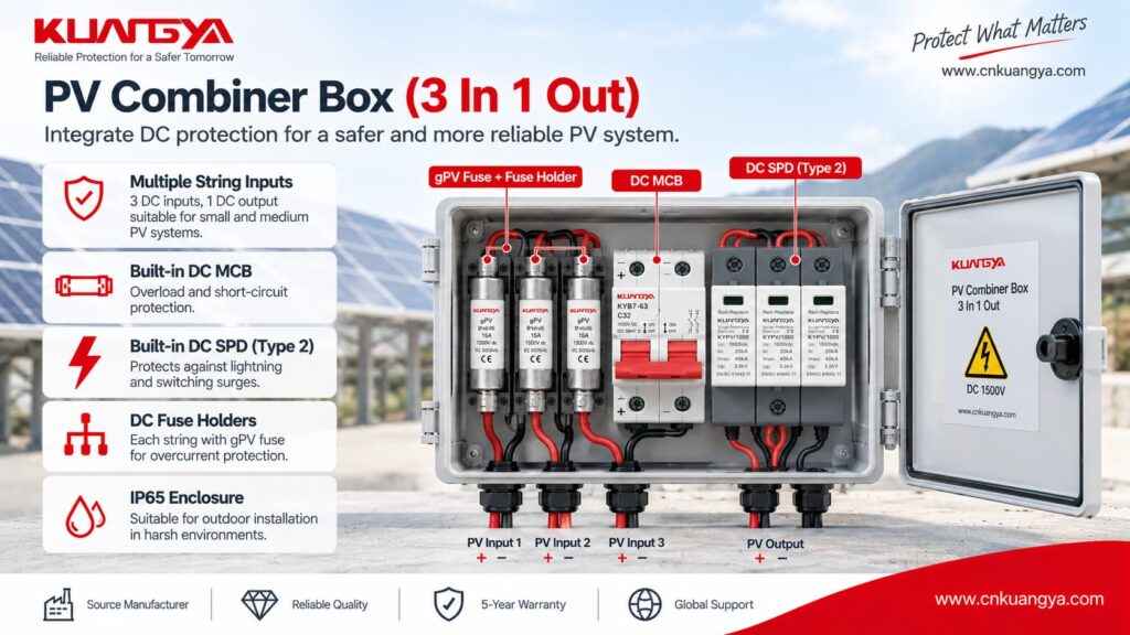
Photovoltaic DC systems require additional care.
A PV DC SPD must be suitable for:
The exact Fusible de protection du parafoudre arrangement can depend on:
Before choosing backup protection, the SPD voltage itself must also be correct.
For more detail, see our DC SPD voltage selection guide for solar PV systems.
Non.
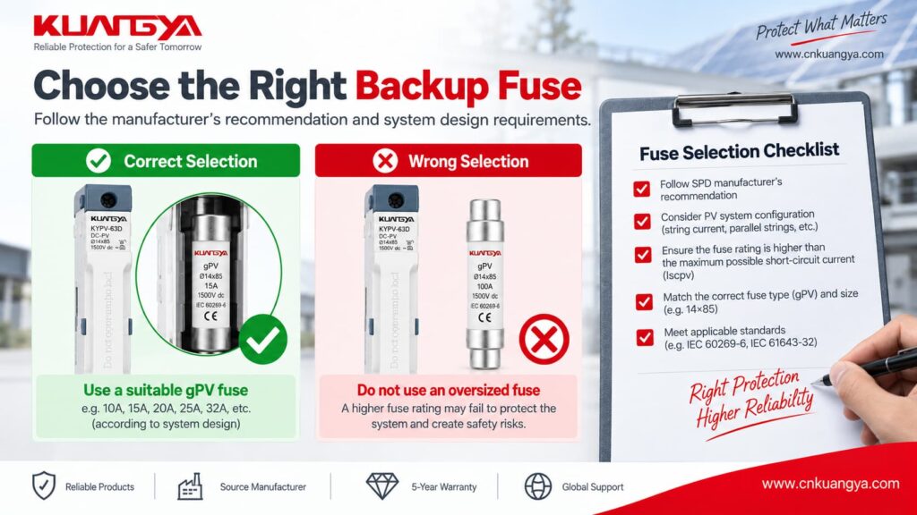
A gPV fuse is specifically designed for photovoltaic applications, but this does pas mean every PV SPD requires a separate gPV backup fuse.
The manufacturer’s instructions must be checked first.
Depending on the system design, existing PV overcurrent protection may already form part of the approved protection arrangement.
If a gPV fuse is required, it must also be suitable for:
For examples of PV-rated fuse links and holders, see KUANGYA’s DC gPV fuse range.
The product page is useful for understanding available PV fuse formats, but final SPD coordination must still follow the SPD manufacturer’s technical data.
Where dedicated backup protection is required, it is normally positioned in the SPD branch so that fault current flowing to the SPD can be interrupted.
A simplified concept is:
Busbar / Supply → F2 → SPD → required protection path
However, the exact wiring depends on:
Always follow the wiring diagram for the exact SPD.
Adding a fuse or breaker should not result in unnecessarily long SPD connections.
SPD connection conductors have inductance.
During a fast-rising surge current, additional lead length can increase the voltage appearing across the protected equipment.
This means backup protection should be coordinated while keeping the SPD connection path short and direct.
For PV systems, there is also another distance issue: the distance between the SPD location and the inverter.
These two distances should not be confused.
For a detailed explanation, see our guide to SPD distance from inverter and SPD connection lead length.
Sometimes.
The existing protective device may be acceptable if:
However, a dedicated SPD breaker can also provide practical advantages such as easier isolation and maintenance.
Le point important est le suivant :
Dedicated protection does not automatically mean correctly coordinated protection.
The device must still match the SPD manufacturer’s requirements.
Because many power SPDs are connected in parallel, the main electrical load can continue operating even after the SPD branch is disconnected.
That means:
Power ON does not necessarily mean surge protection ON.
If the backup fuse opens, the cause should be investigated rather than simply replacing the fuse and re-energizing the system.
Les causes possibles sont les suivantes :
If you suspect the SPD itself has failed, see our guide on comment savoir si un parafoudre est défectueux.
| Erreur | Why It Is Wrong |
|---|---|
| 40 kA SPD = 40 A fuse | Imax and fuse current rating describe completely different electrical quantities |
| Every Type 2 SPD needs 125 A | Backup protection is manufacturer-specific |
| Smaller fuse is always safer | It may disconnect unnecessarily during surge events |
| Internal SPD disconnector means no external protection is ever required | Internal and external protective functions are not necessarily identical |
| 125 A fuse = 125 A breaker | Fuse and breaker operating characteristics differ |
| F2 must always be installed | Existing F1 may already meet the SPD requirement |
| Ignore prospective short-circuit current | SPD protection must be coordinated with available fault current |
| Use AC examples for PV DC SPD | AC and PV DC systems have different requirements |
| Choose only by Imax | Imax does not determine backup-fuse rating |
| Use maximum permitted fuse automatically | “Maximum” is a limit, not necessarily the ideal rating |
Before selecting an fusible ou disjoncteur de protection de secours du parafoudre, check the following:
| Vérifier | Question |
|---|---|
| Exact SPD | What manufacturer and model is installed? |
| Application | AC or photovoltaic DC? |
| Type de DOCUP | Type 1, Type 1+2 or Type 2? |
| Tension | Are Uc/Ucpv suitable for the system? |
| Upstream device | What is F1? |
| Manufacturer limit | What maximum backup protection is specified? |
| Dedicated F2 | Is it actually required? |
| Fault current | What is the prospective short-circuit current? |
| Fuse class | gG, gPV or another specified type? |
| Disjoncteur | What curve and breaking capacity are required? |
| Conductors | Is the conductor cross-section suitable? |
| Terminaux | Can the SPD terminals accept the selected conductors? |
| Lead length | Are SPD connection leads short and direct? |
| Earthing | Is the protection path correctly connected? |
| Indication | Can failure or disconnection be detected? |
If several of these answers are unknown, selecting a backup fuse by guesswork is not appropriate.
IEC 61643-11 covers SPDs intended for connection to AC low-voltage power circuits and specifies performance and safety requirements, tests and ratings.
IEC 61643-31 applies specifically to SPDs intended for the DC side of photovoltaic installations up to 1 500 V CC.
IEC 60364-5-53 covers the selection and erection of electrical equipment for protection, isolation, switching, control and monitoring.
The current IEC consolidated version includes the 2019 base publication plus amendments from 2020 and 2024.
IEC 60364-5-53:2019+A1:2020+A2:2024
Applicable national standards, installation rules and manufacturer instructions must also be followed.
Non.
A separate Fusible de protection du parafoudre is not always necessary.
If the existing upstream protective device already satisfies the manufacturer’s permitted backup-protection conditions, another fuse may not be required.
Some SPDs also include integrated backup protection.
There is no universal fuse size for an SPD.
Use the exact SPD datasheet and check:
Do not calculate the fuse size from Imax alone.
Non.
125 A appears in several manufacturer examples, but it is not a universal Type 2 SPD value.
Published examples show SPDs with different arrangements, including:
Sometimes.
But the circuit breaker’s:
must be suitable.
Do not replace a specified fuse with a breaker simply because both devices have the same ampere rating.
Pas nécessairement.
A red status indicator commonly relates to the condition of the SPD’s internal protection module or disconnection mechanism.
An external backup fuse is a separate protective device.
Therefore, both the SPD status and the upstream or branch protection should be inspected.
Oui.
Because many power SPDs are connected in parallel, the protected load may remain energized even if the SPD has been disconnected.
This means surge protection can be lost while the equipment appears to operate normally.
Non.
The requirement depends on:
Never assume every PV SPD needs the same gPV fuse.
Not directly.
Imax represents a surge-discharge current characteristic.
Fuse current rating relates to overcurrent protection.
A 40 kA Imax rating does not mean a 40 A backup fuse is required.
So, does an SPD need a backup fuse or circuit breaker?
Sometimes yes—but not always as a separate device.
Correct SPD backup fuse selection starts with the manufacturer’s technical data rather than a universal ampere rating.
The correct decision depends on the relationship between:
SPD → F1 → F2 → available fault current → conductors → electrical system
Before installing additional backup protection, first check whether the existing upstream device already satisfies the SPD manufacturer’s requirements.
If dedicated protection is required, verify:
Most importantly:
Never select an SPD backup fuse only from Type 1 / Type 2, In or Imax. Use the exact manufacturer’s backup-protection requirements and the actual system conditions.
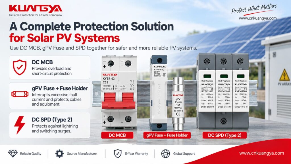
For photovoltaic applications, you can also review KUANGYA’s DC surge protective devices for solar PV systems when comparing Type 2 and Type 1+2 DC SPD options.

