منطقة ونغ يانغ الصناعية يويتشينغ ونتشو 325000
ساعات العمل
من الاثنين إلى الجمعة: 7 صباحاً - 7 مساءً
عطلة نهاية الأسبوع 10 صباحاً - 5 مساءً
منطقة ونغ يانغ الصناعية يويتشينغ ونتشو 325000
ساعات العمل
من الاثنين إلى الجمعة: 7 صباحاً - 7 مساءً
عطلة نهاية الأسبوع 10 صباحاً - 5 مساءً
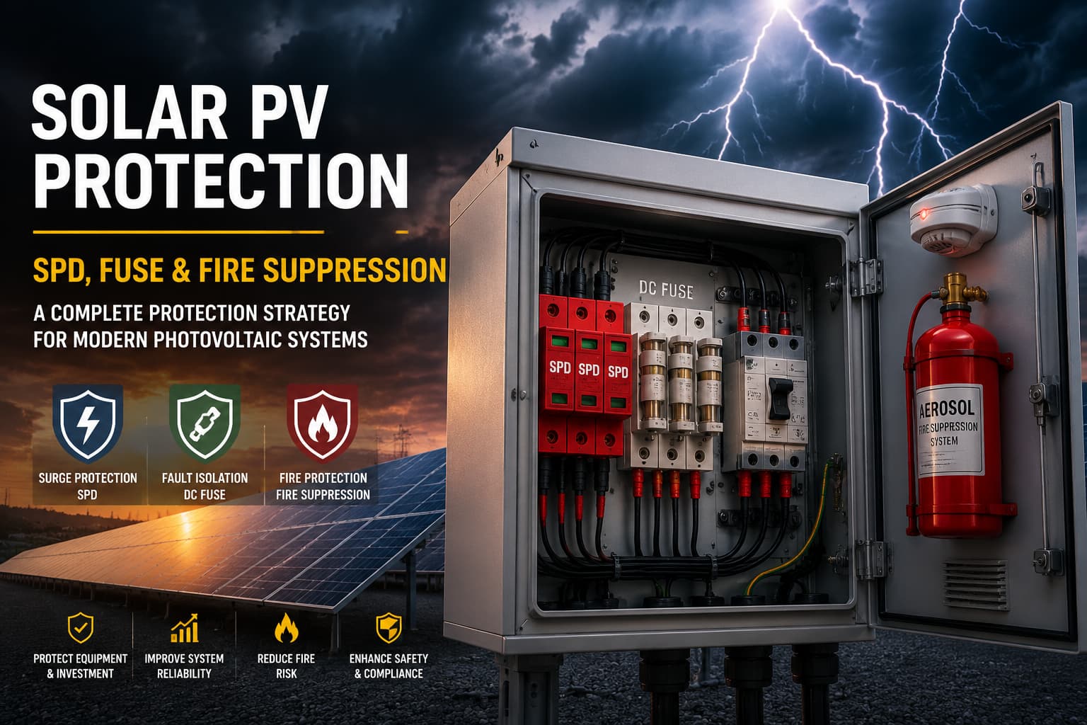
Solar PV Protection is no longer limited to basic grounding or overcurrent protection. Modern photovoltaic systems—especially utility-scale and commercial rooftop installations—face a layered risk profile involving surge events, DC faults, arc flash ignition, and thermal runaway fires.
This article explains a complete protection strategy built around three core elements:
Real-world PV fire incidents from Europe, the United States, and Asia show that most system failures are not caused by a single issue—but by a chain of protection gaps.
We will break down:
Solar PV systems today are not simple power generators. A typical commercial or utility system includes:
The problem is that PV systems do not fail gradually—they fail instantly when protection coordination is missing.
| Risk Factor | Source | Impact |
|---|---|---|
| Lightning surge | Direct or induced strike | Inverter destruction, insulation breakdown |
| أعطال القوس الكهربائي للتيار المستمر (DC) | Loose connectors, aging cables | Fire ignition in combiner boxes |
| التيار الزائد | Short circuits in strings | Cable overheating, fuse rupture |
| الهروب الحراري | Sustained fault + heat buildup | Panel or cabinet fire |
| Switching surges | Grid switching, inverter operation | Semiconductor failure |
A 2022 analysis by the U.S. National Renewable Energy Laboratory (NREL) found that over 60% of PV electrical failures originate from transient overvoltage or poorly coordinated protection devices, not module defects.
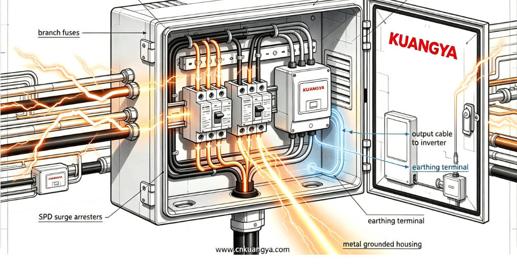
A Surge Protective Device (SPD) is designed to absorb and redirect transient overvoltage caused by:
In PV systems, SPDs are typically installed at:
Unlike AC systems, PV DC circuits:
This creates a situation where surge energy has no natural release path.
When SPD design is incorrect, three failure modes appear:
| وضع الفشل | السبب | النتيجة |
|---|---|---|
| Undersized SPD | Low discharge capacity | Inverter breakdown |
| Poor coordination | No cascading protection | Multiple device failure |
| Aging SPD | No replacement strategy | Silent protection loss |
A 50MW solar farm experienced repeated inverter shutdowns during summer thunderstorms.
Root cause analysis revealed:
النتيجة:
Key lesson: SPD must be layered, not single-point installed.
| جهد النظام | نوع SPD الموصى به | Installation Point | المتطلبات الرئيسية |
|---|---|---|---|
| 600 فولت تيار مستمر | النوع الثاني SPD | صندوق التجميع | Fast response time |
| 1000 فولت تيار مستمر | Type I + II SPD | DC + inverter input | Lightning current handling |
| 1500 فولت تيار مستمر | Type I SPD (high energy) | Outdoor combiner | High discharge capacity |
For a deeper understanding of how SPDs coordinate with PV system design, you can also refer to our technical guide on
DC surge protection and system coordination in solar PV which explains real engineering selection differences between SPD types.
While SPD handles transient events, fuses handle sustained fault current conditions.
In PV systems, fuses are typically used for:
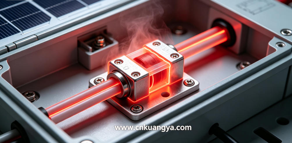
DC fault interruption is significantly harder because:
This is why PV-grade DC fuses must be:
Research on photovoltaic fault current behavior shows that improper fuse coordination can significantly impact distribution protection performance in PV-integrated systems.
Sandia PV Fault Current Impact Study
| السيناريو | السبب | العواقب |
|---|---|---|
| صمامات كهربائية صغيرة الحجم | Incorrect string current calculation | False tripping or overheating |
| Oversized fuse | Avoiding nuisance trips | Failure to protect cables |
| Poor coordination with SPD | Energy mismatch | Cascading equipment failure |
A commercial warehouse rooftop system experienced localized fire in a combiner box.
Investigation found:
النتيجة:
| المكوّن | Coordination Requirement | Design Risk if Ignored |
|---|---|---|
| PV module string | 1.25 × Isc rating | التعثر الكاذب |
| Combiner box fuse | Selective coordination with inverter | انتشار الحريق |
| DC disconnect | Must match fuse curve | Arc persistence |
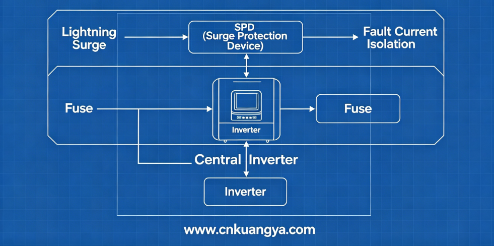
The most common engineering mistake in PV protection is treating SPD and fuse systems as independent layers.
In reality, they must operate as a coordinated protection chain:
If these layers are not coordinated:
| Event Type | SPD Response | Fuse Response | System Outcome |
|---|---|---|---|
| Lightning surge | Absorb/redirect | No action | تشغيل مستقر |
| DC short circuit | Partial suppression | العزل | Safe shutdown |
| Arc fault | Limited effect | May trip | Fire risk if delayed |
| Combined fault | الحمل الزائد | Delayed trip | Equipment damage risk |
In many EPC projects, cost reduction leads to:
This creates a hidden risk:
protection exists on paper, but not in real fault dynamics.
Even with correct SPD and fuse coordination, one risk remains:
Electrical faults that evolve into thermal events before shutdown completes.
هذا هو المكان fire suppression systems become the final protection layer.
Unlike electrical protection, fire suppression:
Common systems include:
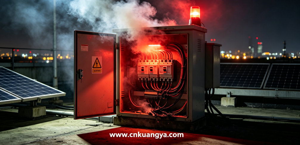
Typical ignition sources:
Once internal temperature exceeds ~200°C, insulation breakdown accelerates rapidly.
A rooftop PV system experienced internal cabinet fire despite:
Root cause:
Fire suppression was absent, resulting in:
| الطبقة | الوظيفة | وقت الاستجابة | Risk Coverage |
|---|---|---|---|
| SPD | الحماية من زيادة التيار (Surge protection) | Microseconds | Lightning, switching |
| فيوز | عزل الأعطال | ميلي ثانية | التيار الزائد، ماس كهربائي |
| إخماد الحرائق | Damage control | ثوانٍ | الهروب الحراري |
In real engineering practice, fire suppression is often treated as an “add-on” rather than part of the electrical protection architecture. This is a structural mistake.
A properly designed Solar PV Protection system should treat fire suppression as:
The final response layer after SPD and fuse coordination fail to fully eliminate thermal escalation risk.
Unlike electrical devices, fire suppression does not “react to current or voltage.” It reacts to temperature rise, smoke, or flame conditions, meaning it bridges the gap between electrical fault and physical damage.
Fire suppression is not installed randomly. It must follow risk concentration points:
| PV System Area | مستوى المخاطرة | Recommended Suppression Placement |
|---|---|---|
| صندوق تجميع التيار المستمر (DC Combiner Box) | عالية | Internal cabinet level |
| Inverter Cabinet | عالية جداً | Integrated suppression module |
| String Monitoring Box | متوسط | Optional localized protection |
| Battery Storage Interface | الحرجة | Dedicated suppression system |
Field failure statistics show that over 70% of PV fire incidents originate inside electrical cabinets, not modules.
Main ignition mechanisms:
Once internal cabinet temperature exceeds 180–250°C, ignition becomes difficult to reverse without automatic suppression.
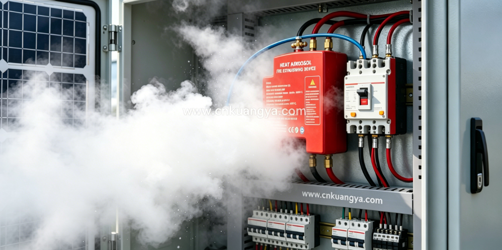
Aerosol systems have become increasingly popular in PV cabinet protection due to compact design and fast discharge.
| الميزة | نظام الهباء الجوي (Aerosol) | Gas System (FM-200 / Novec) | مرشات المياه |
|---|---|---|---|
| Installation space | منخفض جداً | متوسط | عالية |
| Activation speed | 3–10 sec | 10–30 sec | 30+ sec |
| Electrical safety | عالية | عالية | Risk of short circuit |
| بقايا | الحد الأدنى | لا يوجد | High damage risk |
| Cost efficiency | عالية | متوسط | Low for cabinets |
Aerosol systems are particularly effective for:
A 20MW industrial rooftop PV system in Northern Italy experienced a DC arc fault inside a combiner box.
System configuration:
Incident sequence:
النتيجة:
Post-upgrade recommendation:
A reliable Solar PV Protection system must be designed as a layered architecture rather than isolated components.
| الطبقة | نوع الحماية | الوظيفة | وقت الاستجابة |
|---|---|---|---|
| الطبقة الأولى | حماية جهاز الحماية من زيادة التيار (SPD) | تحويل زيادة التيار | Microseconds |
| الطبقة الثانية | حماية الصمامات | عزل الأعطال | ميلي ثانية |
| الطبقة الثالثة | إخماد الحرائق | Thermal containment | ثوانٍ |
This structure ensures that:
Instead of independent operation, real PV protection behaves as a cascade response system:
If any layer is missing or misconfigured, failure cascades downward.
| Missing Component | Likely Failure Outcome | Real-World Impact |
|---|---|---|
| No SPD | Inverter destruction | High replacement cost |
| No fuse coordination | ارتفاع درجة حرارة الكابل | Hidden fire risk |
| No fire suppression | Cabinet fire propagation | Structural damage |
| Poor maintenance | Silent degradation | Delayed failure detection |
Despite well-documented standards, many EPC projects still suffer from recurring design issues.
Many installers assume inverter internal protection is sufficient.
المشكلة:
Consequence:
This is extremely common in cost-optimized projects.
Risk:
| Error Type | السبب | التأثير |
|---|---|---|
| Undersized | Conservative design | التعثر المزعج |
| Oversized | Cost reduction | Fire risk escalation |
Correct fuse sizing requires string-level current modeling, not generic values.
Modern PV protection increasingly requires:
Without this layer, fire suppression becomes reactive instead of predictive.
| نوع النظام | SPD | فيوز | إخماد الحرائق | Outcome During Fault |
|---|---|---|---|---|
| Basic PV system | ❌ | ❌ | ❌ | Catastrophic failure |
| Standard EPC system | ✔ | ✔ | ❌ | Equipment damage possible |
| Advanced protection system | ✔ | ✔ | ✔ | Localized containment |
A fully protected PV system is not “failure-free.” Instead, it ensures:
This is the real engineering objective of Solar PV Protection.
Industry research confirms that effective photovoltaic protection requires integrated coordination of electrical and thermal risk mitigation systems across all balance-of-system components.
PV DC System Safety and Protection Overview
Modern photovoltaic systems operate under high voltage, high energy density, and extreme environmental exposure. No single device can guarantee safety.
A complete Solar PV Protection strategy must integrate:
The real engineering challenge is not selecting one device—but ensuring coordination between all three layers under real fault conditions.
When properly designed, the system does not just “avoid failure”—it ensures that even when failure occurs, it does not escalate into fire, equipment destruction, or system-wide shutdown.
Because SPD and fuses only handle electrical faults. Fire often starts from arc faults, loose connections, or thermal buildup, which may not immediately trigger electrical protection devices.
Yes. Field data shows most PV fires originate inside electrical cabinets. Without suppression, even small arc faults can escalate into full enclosure fires.
The most common mistake is treating SPD, fuse, and fire protection as separate systems instead of a coordinated protection chain.
It depends on surge exposure, but in high-lightning regions, inspection is recommended annually, and replacement typically every 3–5 years or after major surge events.
No. Fire suppression does not prevent electrical faults. It only reduces damage after thermal ignition begins. That is why it must be combined with SPD and fuse protection.
