منطقة ونغ يانغ الصناعية يويتشينغ ونتشو 325000
ساعات العمل
من الاثنين إلى الجمعة: 7 صباحاً - 7 مساءً
عطلة نهاية الأسبوع 10 صباحاً - 5 مساءً
منطقة ونغ يانغ الصناعية يويتشينغ ونتشو 325000
ساعات العمل
من الاثنين إلى الجمعة: 7 صباحاً - 7 مساءً
عطلة نهاية الأسبوع 10 صباحاً - 5 مساءً

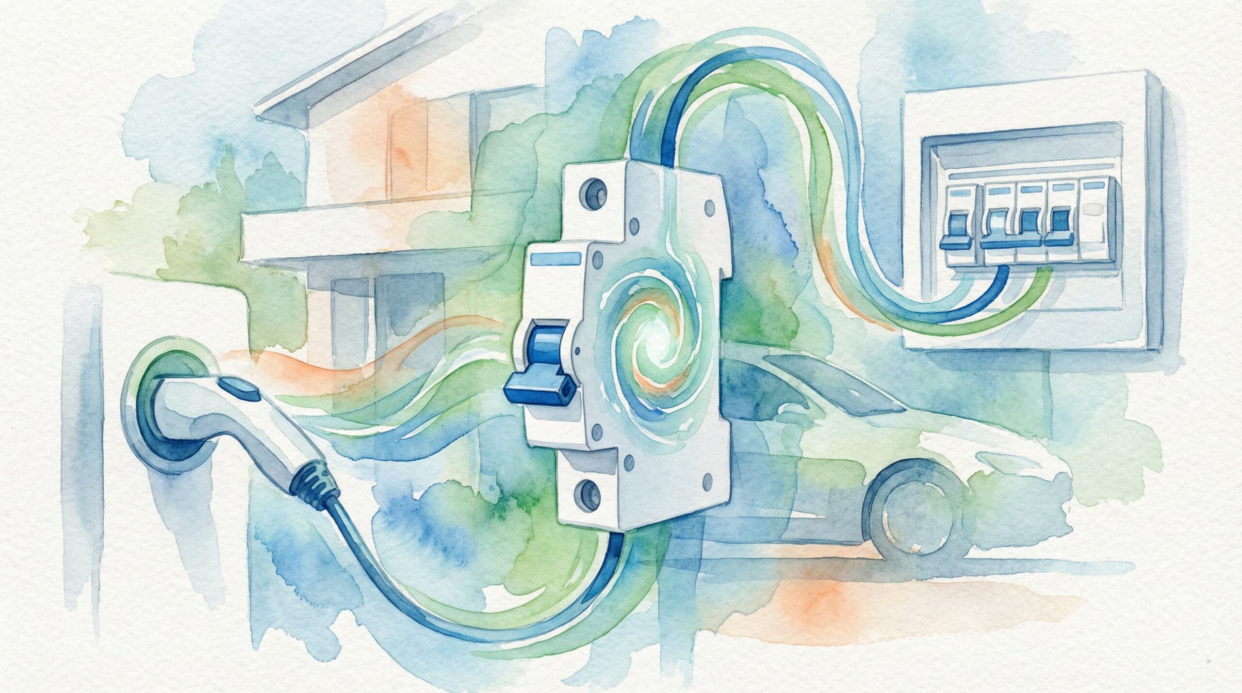
A home EV charger normally needs a dedicated circuit with overload, short-circuit and residual-current protection. The correct RCBO cannot be selected from charger power alone: you must also check the EVSE manufacturer’s instructions, built-in 6 mA DC detection, cable capacity, earthing arrangement, prospective fault current and local wiring rules.
إجابة سريعة: a 7 kW single-phase charger commonly operates at about 32 A, but that does not automatically mean every installation should use a 40 A Type B RCBO. Some chargers permit a Type A or Type F RCBO when a compliant 6 mA RDC-DD is built into the EVSE. The final current rating and trip curve must protect the cable and match the equipment and national requirements.
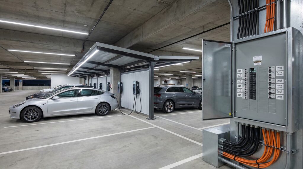
| Charger example | Approximate operating current | Protection starting point | Must still be verified |
|---|---|---|---|
| 3.6–3.7 kW single-phase | About 16 A at 230 V | Dedicated circuit; RCBO rating based on cable and EVSE instructions | RCD type, breaker curve, cable installation and fault current |
| 7.0–7.4 kW single-phase | About 30–32 A at 230 V | Commonly a 32 A charging circuit with suitably selected protection | Do not automatically upsize to 40 A; protect the cable and follow local rules |
| 11 kW three-phase | About 16 A per phase at 400 V | Three-phase dedicated circuit and suitable multi-pole protection | Phase configuration, neutral switching, EVSE DC detection and local rules |
| 22 kW three-phase | About 32 A per phase at 400 V | Higher-capacity dedicated circuit and suitable multi-pole protection | Supply capacity, load management, cable size and protection coordination |
Values are approximate for common nominal supplies. Actual EVSE current limits, voltage, efficiency, cable installation and regulatory requirements determine the design.
An RCBO combines the residual-current function of an RCD with the overload and short-circuit functions of a circuit breaker. Individual RCBO protection also limits the outage to the charging circuit when a fault occurs, which simplifies diagnosis and keeps unrelated household circuits energized.
| Protection function | What it detects | عنصر الاختيار |
|---|---|---|
| الحمل الزائد | Current above the circuit’s normal rating for a period | Rated current, cable capacity and thermal conditions |
| ماس كهربائي | High fault current between conductors | Breaking capacity and prospective fault current |
| Residual current | Current flowing outside the intended live conductors | Type AC/A/F/B, IΔn and operating characteristics |
| Circuit isolation | Disconnection of required live conductors | Pole configuration and national rules |
| الخيار | When it may be suitable | Key condition |
|---|---|---|
| النوع A RCBO | EVSE includes suitable 6 mA DC residual-current detection | Manufacturer and local rules permit Type A with the RDC-DD |
| النوع F RCBO | EVSE and national guidance call for Type F characteristics | Verify the converter waveform and RDC-DD arrangement |
| النوع B RCBO | EVSE lacks suitable DC detection, can produce smooth DC, or Type B is specified | Use a product with the declared Type B characteristics and correct ratings |
Type B is not mandatory for every EV charger. IEC 62955 covers RDC-DDs for Mode 3 charging, and a compliant 6 mA DC-detection arrangement can allow Type A or Type F upstream in many jurisdictions. Conversely, “built-in DC protection” in marketing material is not enough; check the EVSE installation manual and declaration.
A Type B RCBO should not be described as merely detecting “smooth DC up to 6 mA.” Type B devices respond according to their Type B characteristics and rated residual operating current. The 6 mA value is mainly associated with an RDC-DD that prevents smooth DC from impairing an upstream Type A or Type F RCD.
A nominal 7 kW charger is often configured around 32 A on a 230 V single-phase supply, but product settings can differ. Use the rated input current in the installation manual rather than calculating from the marketing power alone.
The cable current-carrying capacity depends on conductor material and size, installation method, ambient temperature, grouping, thermal insulation and route length. The RCBO rated current must not exceed the value permitted for the protected conductor under the applicable wiring rules.
Do not use a universal 125% multiplier unless the local code or design method requires it. Some jurisdictions treat EV charging as a continuous load and specify particular sizing rules; others use different coordination methods. Follow the national standard and EVSE instructions.
Curve B or C selection depends on the EVSE inrush current, earth-fault loop conditions and manufacturer instructions. Do not assume Curve B for every modern charger or Curve C merely to stop nuisance tripping. First identify the cause and verify automatic disconnection requirements.
The RCBO breaking capacity must be suitable for the prospective short-circuit current at the consumer unit. A fixed 6 kA or 10 kA rule cannot be applied worldwide without measuring or calculating the installation fault level and checking local requirements.
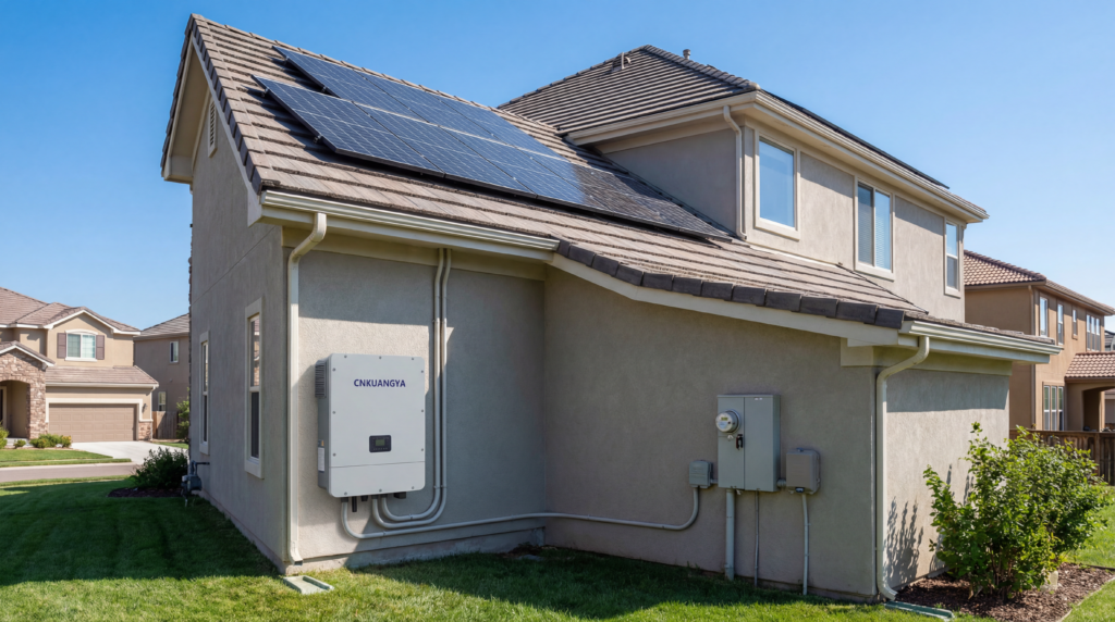
The required earthing measures depend on the supply system and country. In TN-C-S/PME systems, some jurisdictions require protection against an open PEN conductor for outdoor EV charging equipment unless another permitted measure is used. This function can be built into the EVSE or provided externally, but it is separate from Type B residual-current detection.
In TT systems, the earth-electrode resistance, RCD operating current and required disconnection time must be coordinated. An RCBO cannot compensate for an inadequate earthing design. A competent installer should test the protective conductor, electrode where applicable, loop conditions and RCD operation.
| Design item | Single-phase charger | Three-phase charger |
|---|---|---|
| Typical home power | 3.6–7.4 kW | 11 or 22 kW where supply permits |
| الحالي | One phase carries the charging current | Current distributed across three phases |
| RCBO configuration | Commonly 1P+N or 2-pole product depending on design | Suitable 3P+N or 4-pole arrangement |
| الكابل | Live, neutral and protective conductor as required | Three phases, neutral where required, and protective conductor |
| Main design issue | Cable capacity and household maximum demand | Supply capacity, phase balance, neutral and multi-pole isolation |
The existing article identifies the KUANGYA VRL11 as a 1P+N Type B RCBO option for suitable single-phase circuits. Before specifying it, confirm the current product datasheet and declaration for the exact reference. Key project data should include:
| المعلمة | Project check |
|---|---|
| التيار المقنن | Select the exact model within the declared range for the cable and EVSE |
| Rated voltage and frequency | Match the supply and product reference |
| 𞸍 | Confirm the required residual-current sensitivity, commonly 30 mA where additional protection is required |
| نوع التيار المتبقي | Verify the declared Type B characteristics and applicable IEC/EN 62423 requirements |
| RCBO standard | Verify IEC/EN 61009-1 on the exact declaration |
| Trip curve | Choose B or C only when supported by the EVSE and circuit design |
| القدرة الاستيعابية | Confirm against the prospective short-circuit current |
| Poles and isolation | Confirm required line and neutral switching |
| التصديق | Match every certificate to the ordered model and rating |
Use the current manufacturer documents for procurement and do not treat unverified ratings or certification marks as applying to every VRL11 variant.
Many 7 kW chargers operate close to 32 A on a 230 V single-phase supply, but the RCBO must be selected from the EVSE rated current, cable capacity, installation method, trip curve, fault current and local rules. Do not automatically choose 40 A.
No. Type A or Type F with a compliant 6 mA RDC-DD may be permitted. Use Type B when the expected waveform, charger instructions or local rules require it.
Possibly. Confirm IEC 62955 compliance, the disconnection arrangement and the EVSE manufacturer’s instructions. Record that the protection design depends on this charger feature.
A dedicated final circuit is the normal design approach and is required in many jurisdictions. It improves load coordination, fault isolation and continuity for other household circuits.
Neither is universally better. Use the EVSE manufacturer’s guidance and verify inrush, cable protection, prospective fault current and automatic disconnection conditions.
Not automatically. The charger may be rated around 32 A, and the protective-device sizing method depends on the local code, cable and installation conditions.
An RCCB provides residual-current protection and requires separate overcurrent protection. An RCBO combines residual-current, overload and short-circuit functions.
The new charger’s current, phases, RCD type, RDC-DD, open-PEN features and manufacturer instructions must be reviewed. The existing RCBO may or may not remain suitable.
For suitable Type B and other RCBO options, review the current KUANGYA product data. If the design uses a separate residual-current device and MCB, compare the RCCB range. For model-specific documents or quotations, contact KUANGYA with the charger model, supply, cable design and required ratings.

