Промышленная зона Вэньян Юэцин Вэньчжоу 325000
Рабочие часы
Понедельник - пятница: 7AM - 7PM
Выходные: 10AM - 5PM
Промышленная зона Вэньян Юэцин Вэньчжоу 325000
Рабочие часы
Понедельник - пятница: 7AM - 7PM
Выходные: 10AM - 5PM

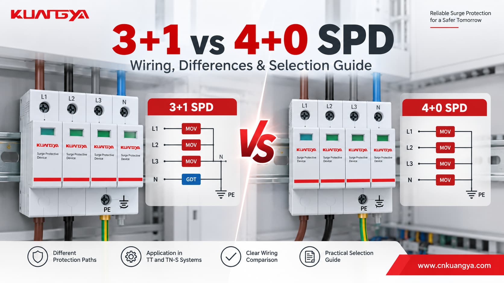
Сравнение УЗИП 3+1 и 4+0 часто начинается с внешнего вида, поскольку обе конфигурации могут выглядеть практически идентично, особенно когда они занимают четыре модуля на DIN-рейке.
Однако с электрической точки зрения они не идентичны.
Основное различие заключается в пути защиты от импульсных перенапряжений.
Типичное устройство защиты от перенапряжений (УЗИП) конфигурации 3+1 использует три пути защиты от фазных проводников к нейтрали:
L1 → N
L2 → N
L3 → N
плюс один дополнительный путь защиты:
N → PE
Типовая конфигурация 4+0 вместо этого обеспечивает пути защиты, подключенные непосредственно к PE, как правило:
L1 → PE
L2 → PE
L3 → PE
N → PE
Эта разница влияет на то, как контролируется импульсное перенапряжение между фазным, нейтральным и защитным заземляющим проводниками, поэтому Конфигурации 3+1 и 4+0 не следует выбирать, просто подсчитывая количество модулей или полюсов.
Правильная конфигурация зависит от системы заземления, требуемых режимов защиты, точки установки и фактической внутренней схемы, заявленной производителем УЗИП.
Краткий ответ: Конфигурация 3+1 обычно используется в системах TT, а также доступна для систем TN-S. Конфигурация 4+0 обычно используется в соответствующих системах TN-S. Всегда проверяйте схему подключения и применимые требования к установке, вместо того чтобы предполагать, что каждое четырехполюсное УЗИП электрически эквивалентно другому.
| Характеристика | УЗИП 3+1 | УЗИП 4+0 |
|---|---|---|
| Типовой путь защиты фазы | L1-N, L2-N, L3-N | L1-PE, L2-PE, L3-PE |
| Защита нейтрали | Раздельный путь N-PE | Путь N-PE как часть четырехполюсной конфигурации |
| Типовая внутренняя конструкция | Варисторы (MOV) на линии L-N + коммутирующий элемент/разрядник (GDT) на линии N-PE | Часто используемые элементы ограничения напряжения, подключенные к PE |
| Прямая защита L-N | Да | Не обязательно как выделенный элемент L-N |
| Прямой путь L-PE | Через согласованный путь L-N + N-PE | Да |
| Стандартное применение | Системы TT и некоторые системы TN-S | Системы TN-S |
| Физические модули | Часто 4 | Часто 4 |
| То же самое, что “4P”? | Не автоматически | Не автоматически |
| Основной критерий выбора | Система заземления + схема подключения + номинальные параметры | Система заземления + схема подключения + номинальные параметры |
Самый важный момент:
Четыре видимых модуля не говорят о том, является ли УЗИП типа 3+1 или 4+0.
Всегда проверяйте схему подключения.
Ключ к выбору между УЗИП 3+1 и 4+0 заключается в понимании внутренних путей защиты, а не в простом подсчете видимых модулей.
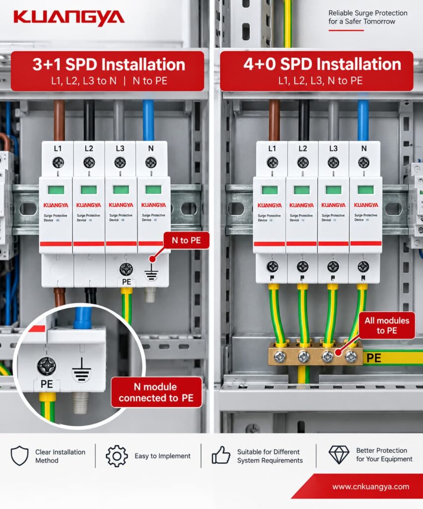
В типичной трехфазной четырехпроводной системе Конфигурация УЗИП 3+1, the three phase conductors are protected relative to neutral.
The protection paths are:
| Protection element | Path |
|---|---|
| Element 1 | L1 → N |
| Element 2 | L2 → N |
| Element 3 | L3 → N |
| Additional element | N → PE |
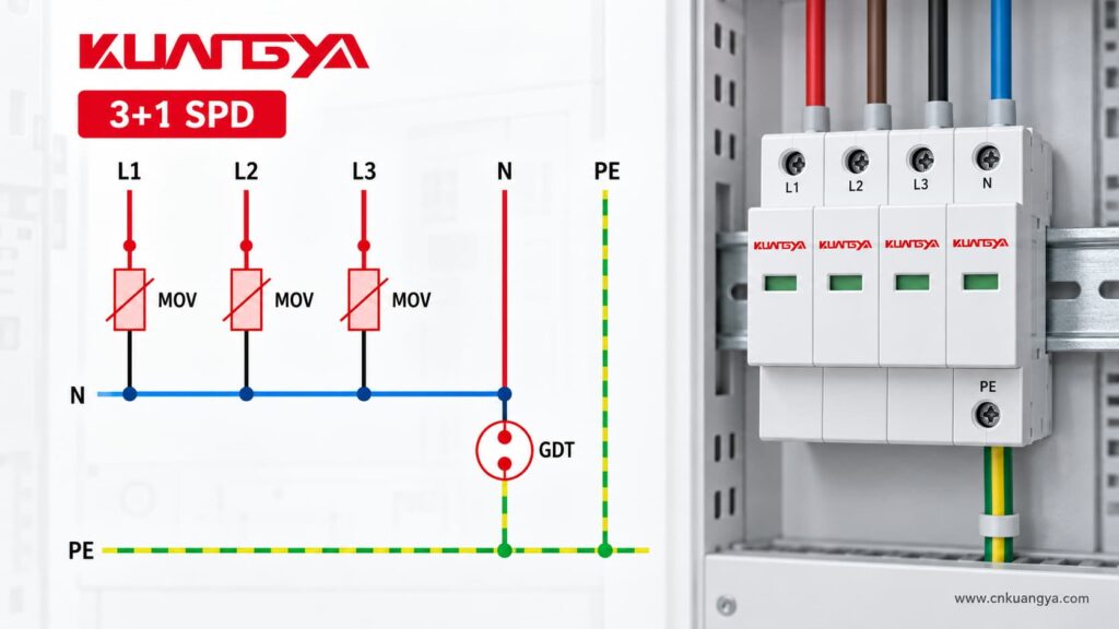
The first three protection elements are commonly voltage-limiting devices such as MOVs — metal oxide varistors.
The additional N-PE protection element is commonly a spark-gap or gas-discharge-based switching element, depending on the product design.
For example, KUANGYA’s 3+1 Type 2 AC SPD uses three MOV protection paths between L1/L2/L3 and N, together with a GDT protection path between N and PE.
Legrand likewise describes its 3P+N / 3+1 configuration as providing L-N and N-PE protection, with the neutral pole protected by an encapsulated spark gap.
L1 ──[MOV]──┐
L2 ──[MOV]──┤
L3 ──[MOV]──┤── N ──[GDT / switching element]── PE
This is a simplified illustration. The actual internal circuit and protective technology must always be confirmed from the manufacturer’s datasheet.
Типичный УЗИП 4+0 uses four protection paths referenced to protective earth.
A common arrangement is:
L1 ──[SPD]── PE
L2 ──[SPD]── PE
L3 ──[SPD]── PE
N  ──[SPD]── PE
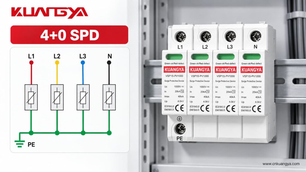
In this configuration, the three phases and neutral each have a protection path toward PE.
For example, KUANGYA’s VSP1S40 4+0 model is intended for TN-S systems and provides L-PE and N-PE protection modes.
DEHN also identifies its four-path TN-S models as 4+0 configurations, while offering separate 3+1 products for TT and TN-S systems.
However, this is where buyers need to be careful.
Different manufacturers may use terms such as:
4P
3P+N
4+0
3+1
in slightly different ways in catalog titles.
Поэтому:
Do not identify the internal SPD topology from the product name alone. Check the circuit diagram.
The real difference is not the number of modules.
It is where the surge voltage is controlled and where surge current is diverted.
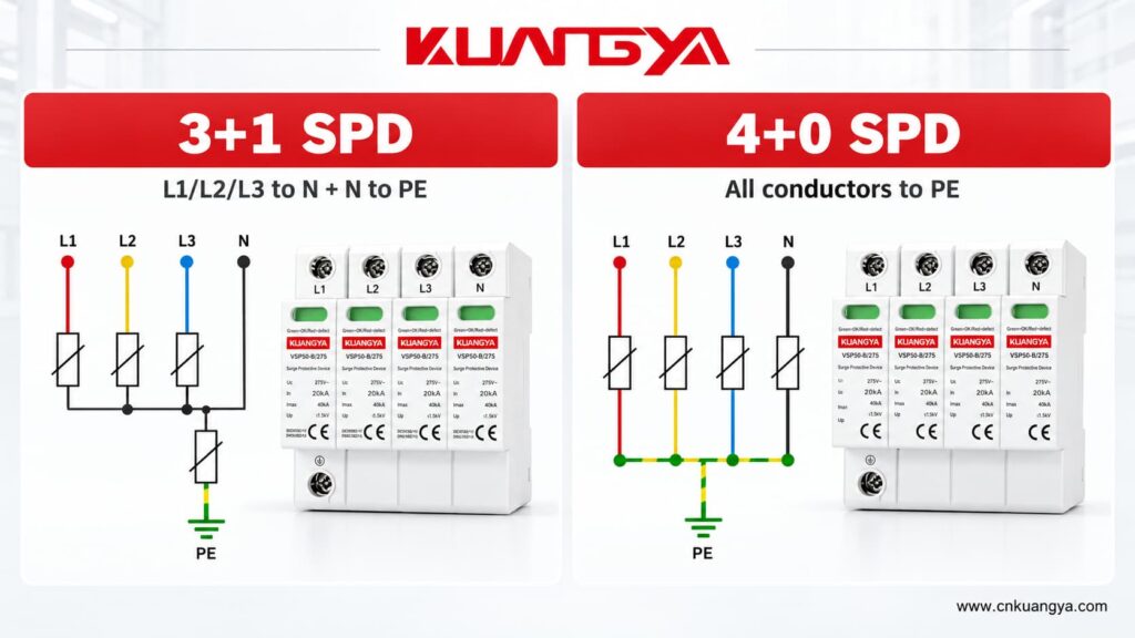
A 3+1 configuration provides direct protection between:
L1-N
L2-N
L3-N
followed by a separate path between:
N-PE
This provides direct line-to-neutral protection for loads connected between phase and neutral.
A typical 4+0 arrangement provides direct protection between the active conductors and PE:
L1-PE
L2-PE
L3-PE
N-PE
The line-to-neutral voltage may also be influenced during a surge through the combined operation of protection elements, but this is not the same topology as providing a dedicated L-N protective element.
This is why two SPDs with:
can still have very different internal circuits.
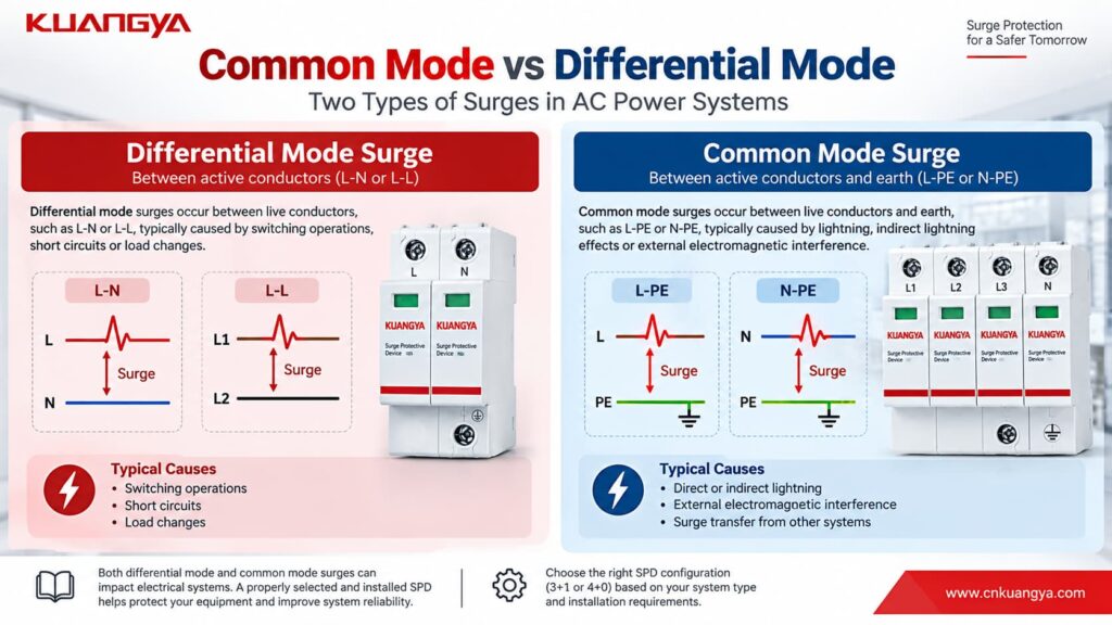
Понимание common-mode and differential-mode surge voltage makes the 3+1 vs 4+0 difference easier to understand.
A differential-mode surge appears between active conductors.
Примеры включают:
L-N
L1-L2
L2-L3
For a single-phase load connected between L and N, the L-N voltage is particularly important.
A typical 3+1 topology provides a direct L-N protective path.
A common-mode surge appears between an active conductor and earth.
Примеры включают:
L1-PE
L2-PE
L3-PE
N-PE
Lightning-induced transients can create significant common-mode voltage relative to earth.
A typical 4+0 configuration provides direct active-conductor-to-PE paths.
A 3+1 configuration handles the surge through its coordinated L-N and N-PE protection network.
Therefore, when comparing SPDs, asking:
“How many poles does it have?”
is less useful than asking:
“Which protection modes does it provide?”
This is one of the most important differences buyers notice when opening a 3+1 SPD.
The N-PE module may look different from the three L-N modules.
That is not necessarily a manufacturing inconsistency.
It may use a different protection technology because it performs a different electrical function.
In many 3+1 designs:
L-N = MOV
while:
N-PE = GDT or spark-gap-based element
DEHN, for example, offers dedicated N-PE spark-gap arresters intended for 1+1 and 3+1 configurations in TT systems.
KUANGYA’s Type 2 3+1 AC SPD similarly uses MOV protection between the phases and neutral, with a GDT between neutral and PE.
One advantage of a suitable switching N-PE element is that it does not create the same continuous leakage path between N and PE as a permanently voltage-limiting element might.
However, the exact technology, follow-current capability, TOV behavior and ratings remain product-specific.
Never assume that every 3+1 SPD uses exactly the same internal components.
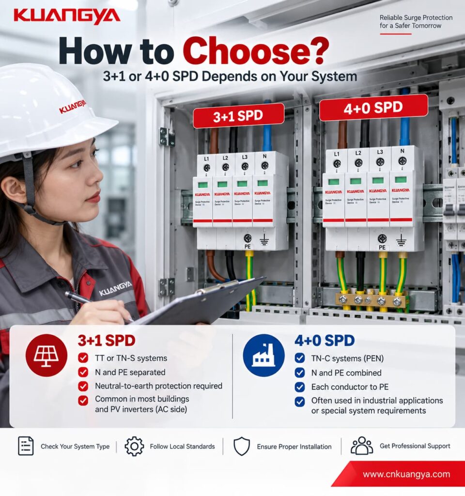
For 3+1 vs 4+0 SPD selection, the earthing system is one of the most important factors to confirm. For a typical IEC-based TT earthing system, a 3+1 configuration is widely used.
In a TT system:
A 3+1 SPD provides:
L1 → N
L2 → N
L3 → N
plus:
N → PE
This topology is commonly used to coordinate surge protection with the TT earthing arrangement.
DEHN’s technical guidance shows the 3+1 circuit for TT systems, and current DEHN products are specifically offered for TT and TN-S installations using this configuration.
It is tempting to remember:
TT = 3+1
That is useful as a starting point, but it is not a complete SPD specification.
You must still check:
TN-S systems have separate:
N — Neutral
и
PE — Protective Earth
conductors.
Both 3+1 and suitable 4+0 products can be found for TN-S applications.
For example, DEHN currently offers:
4+0 products specifically for TN-S
и:
3+1 products for TT and TN-S systems.
KUANGYA follows a similar product distinction: the VSP1S40 4+0 version is specified for TN-S, while the corresponding 3+1 configuration is available for TT and TN-S systems.
Therefore, it is not technically correct to say:
“TN-S always needs 4+0.”
или:
“3+1 is only for TT.”
Instead, the required protection modes, installation rules and manufacturer-approved configuration should determine the selection.
This is where pole-count mistakes become particularly common.
In a TN-C section of an installation, neutral and protective-earth functions are combined in a single:
PEN conductor
A typical three-phase arrangement therefore uses:
L1-PEN
L2-PEN
L3-PEN
often described as a 3+0 configuration.
There is no separate N conductor and PE conductor at that point, so a separate N-PE protection path would not describe the conductor arrangement correctly.
A TN-C-S installation contains two different sections.
Before the PEN conductor is separated:
TN-C principles apply.
After PEN is separated into:
N + PE
the downstream section behaves as TN-S.
Поэтому:
The correct SPD configuration depends on where the SPD is installed relative to the PEN separation point.
Do not select a 3P or 4P SPD simply because the overall building supply is described as TN-C-S.
Check the actual conductor arrangement at the SPD installation point.
The easiest way to identify a 3+1 vs 4+0 SPD configuration is to check the manufacturer’s wiring diagram rather than count the cartridges.
Look at the wiring diagram.
L1 ── SPD ── N
L2 ── SPD ── N
L3 ── SPD ── N
N  ── SPD ── PE
Look for three phase-to-neutral paths plus one neutral-to-earth path.
The N-PE element may also have a different symbol from the L-N elements.
L1 ── SPD ── PE
L2 ── SPD ── PE
L3 ── SPD ── PE
N  ── SPD ── PE
Look for four protection paths referenced toward PE.
When requesting a quotation, do not write only:
“Need 4P SPD.”
Instead, provide:
Система: 230/400 В ПЕРЕМЕННОГО ТОКА
Earthing system: TT / TN-S / TN-C / TN-C-S
Required SPD type: Type 1 / Type 2 / Type 1+2
Topology: 3+1 / 4+0 if known
Uc: required value
In / Imax / Iimp: required values
Remote signal: Да / Нет
This greatly reduces the chance of receiving a product with the correct number of modules but the wrong internal connection.
Neither topology is universally “better.”
They solve surge-protection paths differently.
A correctly selected 4+0 SPD can be appropriate for a suitable TN-S application.
A correctly selected 3+1 SPD can be appropriate for TT and suitable TN-S applications.
The important question is not:
Which one is stronger?
А в том:
Which topology matches the electrical network and the protection modes required at this installation point?
Performance must then be evaluated using the actual electrical specifications.
К ним относятся:
| Параметр | What to check |
|---|---|
| Uc | Максимальное длительное рабочее напряжение |
| Вверх | Уровень напряжения защиты |
| На сайте | Номинальный разрядный ток |
| Imax | Maximum discharge current for applicable Type 2 products |
| Iimp | Lightning impulse current for applicable Type 1 products |
| Isccr / short-circuit rating | Compatibility with available fault current |
| Backup protection | Required fuse or circuit breaker |
| TOV performance | Behavior under temporary overvoltage |
| Remote contact | Whether remote monitoring is required |
Do not judge SPD performance simply by the largest kA number on the label.
Нет.
This is an easy naming mistake.
3+1 describes the SPD protection topology.
It does not mean:
Type 3 + Type 1.
If you are unsure about the difference between SPD classifications, see our guide to Type 1, Type 2 and Type 3 SPDs.
SPD classification and topology are separate characteristics.
AC power SPDs are covered by IEC 61643-11, which specifies performance and safety requirements, tests and ratings for surge protective devices connected to AC low-voltage power systems.
For example, a 3+1 SPD may be:
Тип 1
Тип 2
или
Тип 1+2
depending on its tested performance.
Likewise, a 4+0 product can also be offered in different SPD Types.
Поэтому:
3+1 tells you how the protection paths are arranged. Type 1, Type 2 and Type 1+2 tell you about the SPD’s test classification and surge-current duty.
Not automatically.
Even if both products have:
their protection modes can be different.
Before replacing one topology with another, verify:
The replacement should be based on the complete electrical design, not only mechanical compatibility.
Circuit breakers and SPDs should not be interpreted in exactly the same way.
A four-pole circuit breaker normally refers to conductors passing through switching/protection poles.
An SPD generally works in parallel with the circuit and provides a temporary low-impedance surge path.
So “four-pole SPD” does not automatically tell you everything about:
If you are unfamiliar with this difference, see our guide Почему УЗИП подключается параллельно, а не последовательно?
The circuit diagram remains more important than the number of visible modules.
Four cartridges do not automatically mean a particular topology.
Check the internal diagram.
A four-module product can use different internal protection arrangements.
“4P” and “3+1” should not be treated as synonyms without checking the manufacturer’s circuit.
3+1 products are widely used for TT, but manufacturers such as DEHN and KUANGYA also specify certain 3+1 products for TN-S systems.
The network arrangement before and after the PEN separation point is different.
Confirm where the SPD will actually be installed.
A 40 kA SPD is not automatically more suitable than a 20 kA product simply because the number is larger.
Topology, SPD Type, Uc, Up, In, Iimp, fault-current conditions and coordination must all be considered.
The SPD’s surge-current rating is not the same thing as the rating of its backup fuse or circuit breaker.
Do not calculate:
Imax 40 kA = 40 A backup fuse.
That is incorrect.
Backup protection must be selected according to the manufacturer requirements and the installation’s overcurrent and prospective short-circuit conditions.
For a detailed explanation, see our guide Резервный предохранитель для УЗИП: 7 правил правильного выбора.
SPD selection and installation should also follow applicable requirements such as IEC 60364-5-53 and local electrical regulations.
During a fast surge event, conductor inductance creates additional voltage.
Long or looped connecting wires can therefore increase the effective voltage reaching the protected equipment.
Use the shortest practical routing permitted by the installation design and applicable requirements.
Never create an unauthorized N-PE connection simply to make SPD wiring easier.
This is particularly important in TT and TN-C-S systems.
The neutral, PE and PEN arrangement is part of the earthing system itself.
The SPD manufacturer may specify:
Follow the product data rather than estimating the backup device from In or Imax.
In installations containing RCDs or RCCBs, SPD location and topology can affect the current path during transient or fault conditions.
TT systems require particular attention to the relationship among:
SPD + RCD + N + PE
Follow the applicable installation rules and manufacturer guidance.
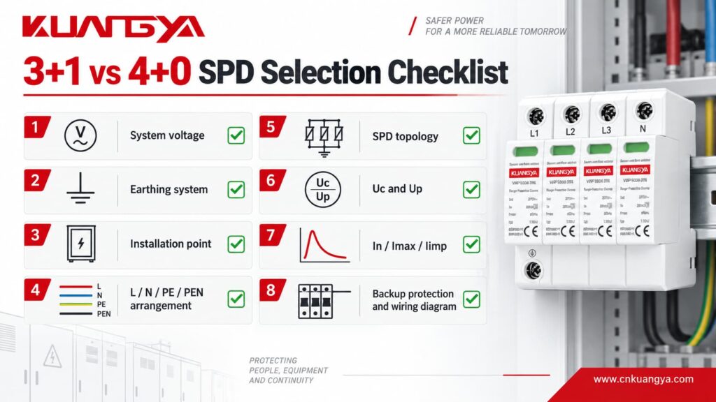
Before ordering or approving an AC SPD, confirm the following:
| Проверьте | Вопрос |
|---|---|
| Напряжения системы | Is it 230/400 V, 120/208 V or another system? |
| Частота | 50 Hz or 60 Hz? |
| Система заземления | TT, TN-S, TN-C, TN-C-S or IT? |
| Installation point | Before or after the PEN split? |
| Нейтральный | Is N distributed at the SPD location? |
| PE/PEN | Is the protective conductor PE or PEN? |
| Топология | 3+0, 4+0, 3+1 or another configuration? |
| Режимы защиты | L-N, L-PE, N-PE and/or L-L? |
| Тип СПД | Type 1, Type 2 or Type 1+2? |
| Uc | Is the maximum continuous voltage suitable? |
| Вверх | Is the protection level suitable for downstream equipment? |
| In / Imax | Are the Type 2 discharge ratings suitable? |
| Iimp | If Type 1 is required, is Iimp specified? |
| Short-circuit rating | Is the SPD compatible with available fault current? |
| Backup device | Is the required fuse/MCB confirmed? |
| TOV | Is temporary-overvoltage behavior specified? |
| Remote signal | Is remote monitoring required? |
| Wiring diagram | Has the actual manufacturer circuit been checked? |
A buyer who completes this checklist is much less likely to purchase the wrong SPD simply because two products look similar.
Consider two Type 2 AC SPDs.
Internal paths:
L1-N
L2-N
L3-N
N-PE
Internal paths:
L1-PE
L2-PE
L3-PE
N-PE
From the front, these two devices may appear very similar.
Their surge-current ratings may even be identical.
But their protection topology is different.
That is why:
Same voltage + same kA + same number of modules does not mean the SPDs are electrically interchangeable.
KUANGYA offers a range of Устройства защиты от перенапряжения переменного тока for different low-voltage distribution systems.
For example, the VSP1S40 Type 2 series includes:
| Конфигурация | Typical network application | Protection arrangement |
|---|---|---|
| 3+0 | TN-C | L-PEN |
| 4+0 | TN-S | L-PE / N-PE |
| 1+1 | TT / TN-S single phase | L-N + N-PE |
| 3+1 | TT / TN-S three phase | L1/L2/L3-N + N-PE |
The 3+1 design uses high-energy MOV elements for the L-N paths together with a GDT in the N-PE path, while the 4+0 version uses a different protection arrangement suited to its declared network application.
When requesting a model, provide the actual:
network voltage + earthing system + SPD Type + required surge ratings + remote contact requirement
rather than ordering only by the number of poles.
Physically, a 3+1 SPD may use four positions or modules, but “3+1” describes the protection topology rather than merely the mechanical pole count.
Check the product wiring diagram.
Not universally.
The correct choice depends on the earthing system, required protection modes, installation rules and product design.
A correctly selected 4+0 device can be suitable for TN-S applications, while 3+1 is widely used in TT and also in suitable TN-S systems.
In many 3+1 designs, the three phase-to-neutral protection elements use MOV technology, while the N-PE path uses a GDT or spark gap.
The fourth module therefore performs a different electrical function.
Potentially, yes.
Manufacturers including DEHN and KUANGYA offer 3+1 products declared for TT and TN-S applications. Final selection should still follow the product datasheet and applicable installation requirements.
Do not assume that a generic 4+0 product is suitable.
TT systems require careful consideration of the protection arrangement, N-PE path, RCD location and applicable installation requirements.
Use an SPD specifically declared by the manufacturer for the intended TT configuration.
Нет.
3+1 is a connection topology.
Type 1, Type 2 and Type 3 are SPD classifications associated with different test and application requirements.
They are separate concepts.
Нет.
Manufacturers may use terms such as 4P, 3P+N, 3+1 and 4+0 differently in short product descriptions.
Always verify the internal wiring diagram and declared protection modes.
Start with the earthing system and actual conductor arrangement at the installation point.
Then check:
protection topology → SPD Type → Uc → Up → surge-current ratings → short-circuit conditions → backup protection → installation requirements.
Do not start with the largest kA value.
The most important point in a 3+1 vs 4+0 SPD comparison is that the difference is not simply the number of modules.
A typical 3+1 SPD provides three phase-to-neutral protection paths plus a separate neutral-to-earth path:
L1-N + L2-N + L3-N + N-PE
A typical 4+0 SPD instead provides four protection paths referenced toward PE:
L1-PE + L2-PE + L3-PE + N-PE
3+1 is widely used in TT systems and can also be used in suitable TN-S applications. 4+0 is commonly available for TN-S systems.
However, the earthing system alone is not the complete specification.
Before selecting an SPD, verify the actual wiring diagram, protection modes, Uc, Up, In, Imax or Iimp, short-circuit conditions, backup protection and manufacturer installation requirements.
The most useful rule is simple:
Do not choose an SPD by counting modules. Choose it by checking the network, protection paths and electrical ratings.
Technical references used to verify the concepts in this guide include:
IEC/EN 61643-11 — Low-voltage surge protective devices for AC power systems.
IEC 60364-5-53 — Selection and erection of electrical equipment, including SPD connection and application principles.
DEHN — Technical documentation for 3+1 TT/TN-S and 4+0 TN-S surge arrester configurations.
Legrand — Technical documentation identifying 3P+N / 3+1 L-N and N-PE protection modes.
КУАНЬЯ — VSP1S40 Type 2 AC SPD technical data and internal connection configurations.

